REHM BOOSTER 140 User manual

BOOSTER 140
BETRIEBSANLEITUNG
OPERATING INSTRUCTIONS
INSTRUCTIONS DE SERVICE
INSTRUCCIONES DE SERVICIO
ISTRUZIONI PER I´USO
GEBRUIKSAANWIJZING
DGB FEINL

2
Produktidentifikation
Schweißinverter
Artikelnummer
BOOSTER 140 150 3140
BOOSTER 140 SET 150 3141
Rehm GmbH u. Co. KG
Ottostr. 2
D-73066 Uhingen
Telefon: 07161/3007-0
Telefax: 07161/3007-20
Internet: http://www.rehm-online.de
Dok.-Nr.: 730 1220
Ausgabedatum: 07:07
©Rehm GmbH u Co. KG, Uhingen, Germany 2004
Der Inhalt dieser Beschreibung ist alleiniges Eigentum der Firma
Rehm GmbH u. Co. KG
Weitergabe sowie Vervielfältigung dieses Dokuments, Verwertung und
Mitteilung seines Inhalts sind verboten, soweit nicht ausdrücklich gestattet.
Zuwiderhandlungen verpflichten zu Schadenersatz. Alle Rechte für den Fall
der Patent-, Gebrauchsmuster- oder Geschmacksmustereintragung
vorbehalten.
Eine Fertigung anhand dieser Unterlagen ist nicht zulässig.
Änderungen vorbehalten.
Bezeichnung
Typ

3
D
1 Allgemeine Beschreibung
Sehr geehrter Kunde,
Sie haben einen REHM - Schweißinverter und damit ein deutsches Markengerät erworben.
Wir danken Ihnen für das Vertrauen, das Sie in unsere Qualitätsprodukte setzen.
Der BOOSTER 140 ist ein professionelles Schweißgerät für das Elektroden-Schweißen aller
handelsüblichen Elektroden (Elektroden-Schweißen entspricht Lichtbogen-Hand-Schweißen
nach DIN1910). Die digitale Prozessorsteuerung und das hochdynamische Leistungsteil mit
seiner Taktfrequenz von 100 kHz bieten Ihnen beste Schweißeigenschaften. Sie brauchen
nur noch den richtigen Schweißstrom zu wählen. Das geringe Gewicht von nur 4,9 kg und
die ausgesprochen kompakten Abmessungen sorgen für eine einfache Handhabung.
Zusammen mit dem robusten Stahl-Gehäuse wird der BOOSTER 140 so zum idealen
Begleiter in der Werkstatt und für den harten Außeneinsatz auf der Baustelle.
Technische Daten:
-140 A maximaler Ausgangsstrom bei einer Einschaltdauer von 40% (20°C)
-110 A Ausgangstrom bei einer Einschaltdauer von 100% (20°C)
-hohe Leerlaufspannung von 91V
-HotStart + Arc Force
-kontinuierliche elektronische Netzspannungsüberwachung
-Anti-Stick-Funktion – kein Ausglühen der Elektrode beim versehentlichen Festkleben
-Schutzklasse IP23: Einsatz auch bei ungünstigen Umgebungsbedingungen
Der BOOSTER 140 ist universell für alle Schweißaufgaben an nichtrostenden Stählen, hoch-
und niedriglegierten Stählen sowie an Buntmetallen einsetzbar und so der ideale Partner für
alle Fälle.

4
2 Folgende Sicherheitshinweise sind zu beachten
Es ist trockene Schutzkleidung zu tragen sowie Augen und Gesicht sind mit Schweißschild
zu schützen (siehe BGR 500). Das Gerät ist an geerdeten Steckdosen und mit Netzkabeln
mit ordnungsgemäß ange- schlossenem Schutzleiter zu betreiben.
Das Gerät darf nur durch ausgebildetes Fachpersonal gewartet werden. Bei Problemen steht
Ihnen der REHM-Kundenservice unter der Tel.-Nr. 07161/3007-85 zur Verfügung.
Beim Betrieb dieses Gerätes ist die Unfallverhütungsvorschrift Schweißen, Schneiden und
verwandte Verfahren (BGR 500) zu berücksichtigen. Die wesentlichen Gefahren sind:
Brand und Explosion
Schadstoffe (Gase, Dämpfe, Rauch / Stäube)
optische Strahlung
elektrische Gefährdung
Handhabungsfehler
Die BOOSTER-Schweißanlagen sind gemäß EN 60974-1 Lichtbogenschweißeinrichtungen -
Schweißstromquellen für Überspannungskategorie III und Verschmutzungsgrad 3 und
gemäß EN 60974-10 Lichtbogenschweißeinrichtungen - elektromagnetische Verträglichkeit
(EMV) ausgelegt und dürfen nur mit Netzversorgungssystemen verwendwet werden, die ein
Dreiphasen-Vier-Draht-Sytem mit geerdetem Neutralleiter sind.
Die Geräte sind für das Schweißen von Elektroden vorgesehen. Sie dürfen nur von
Personen, die in der Anwendung und Wartung von Schweißgeräten ausgebildet und
geschult sind, betrieben werden.
Das Gerät ist gemäß EN 60974-10 für Gruppe 2 Klasse A ausgelegt und eignet sich für den
Einsatz in allen Bereichen, außer dem Wohnbereich und solchen Betrieben, die direkt an ein
Niederspannungsnetz angeschlossen sind, das (auch) Wohngebäude versorgt.
3 Funktionsbeschreibung
3.1 Das REHM-Bedienfeld
3.1.1 Übersicht
Die Bedienung des Booster 140 erfolgt über das in Bild 3.1 dargestellte REHM- Bedienfeld.
A
140
120
100
8060
40
20
5
7301210
12
Bild 3.1Bedienfeld BOOSTER 140
Das Bedienfeld ist in folgende Bereiche unterteilt:
cKontrollleuchten für Betrieb und Übertemperatur
dDrehknopf für die Schweißstromvorwahl

5
D
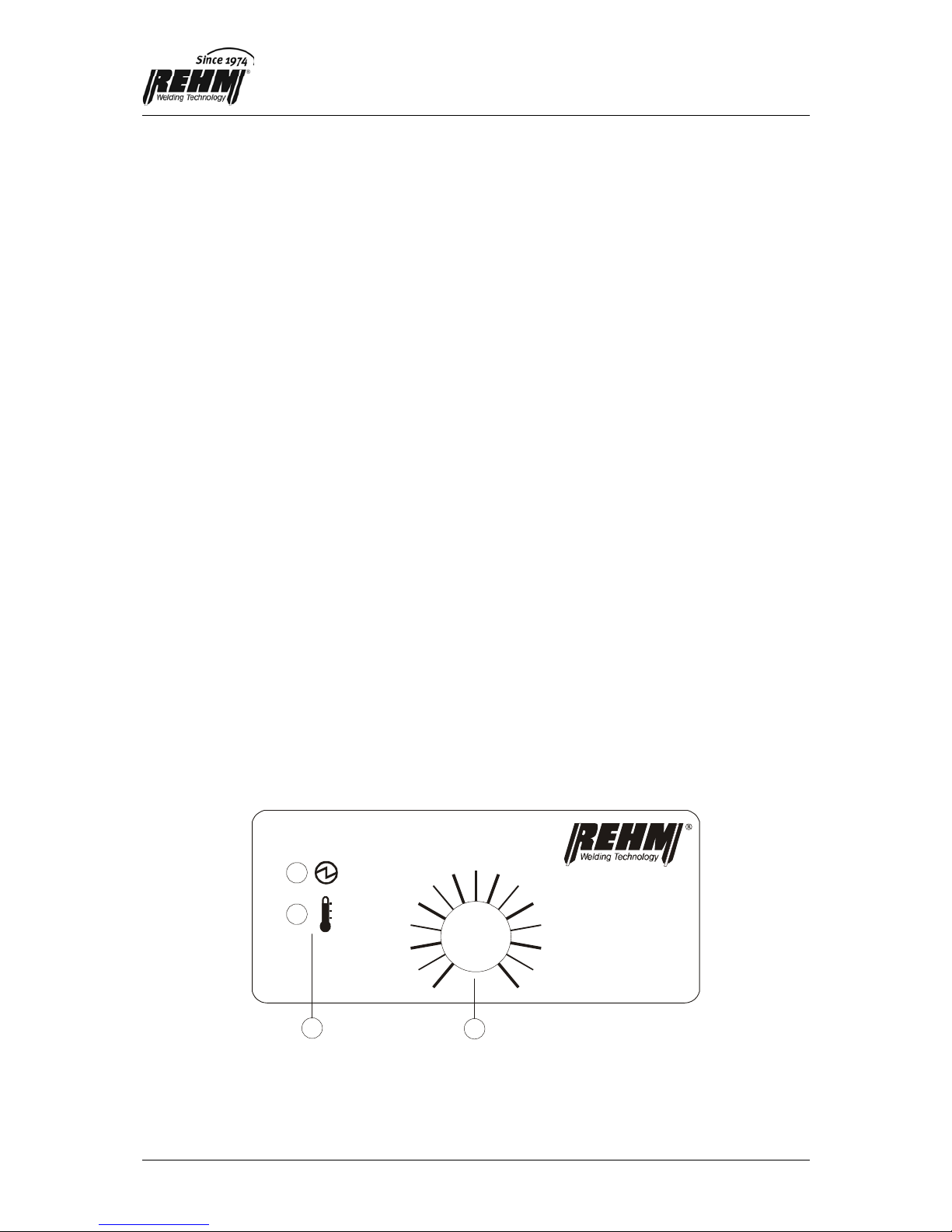
3.1.2 Symbole und deren Bedeutung
Die Symbole auf dem Bedienfeld haben folgende Bedeutungen:
Leerlaufspannung liegt am Brenner oder Elektrodenhalter an.
Temperaturanzeige.
Die Leuchtdiode (gelb) leuchtet bei Überschreitung der maximal zulässigen
Gerätetemperatur. Solange diese Leuchtdiode leuchtet, ist der
Ausgangsstrom abgeschaltet. Nach Abkühlung des Gerätes erlischt die
Leuchtdiode und es kann automatisch wieder geschweißt werden.
Bei blinkender Anzeige wurde interne Überwachung ausgelöst. Durch Aus- und
Einschalten am Netzschalter wird das Gerät wieder einsatzbereit. Bitte den
REHM-Kunden-Sevice (RKS) darüber informieren.
3.2 Elektrodenschweißen
Das Gerät eignet sich zum Schweißen aller handelsüblichen Elektroden, wobei der maximale
Strom 140 A beträgt. Mit diesem Strom können handelsübliche Elektroden bis zu 3,25 mm
Durchmesser verschweißt werden.
Die Polung und Stromeinstellung für die einzelnen Elektroden können Sie aus den
Herstellerunterlagen der Elektroden entnehmen. Der Elektrodenhalter wird an der
Schweißstrombuchse eingesteckt, welche die für die Elektrode angegebene Polarität hat
(siehe Kapitel 3.4 und 3.5).
Sie brauchen lediglich den für Ihre Schweißaufgabe und für die dafür gewählte Elektrode den
passenden Schweißstrom und die richtige Polarität zu wählen. Den Rest erledigt der Booster
140 für Sie. Folgende Funktionen sorgen automatisch für gute Schweißarbeiten:
3.2.1 Hot Start
Beim Beginn der Schweißarbeit liefert der Booster 140 kurzfristig einen höheren Strom als
der eingestellte Schweißstrom (maximal 140A). Dies sorgt für eine gute Zündeigenschaft und
einen schnellen stabilen Lichtbogen.
3.2.2 Arc Force
Während der Schweißarbeit überwacht der Booster 140 den Schweißstrom und die
Schweißspannung. Erkennt der Booster 140, dass ein Tropfenübergang im Kurzschluss
stattfindet, so liefert er kurzfristig einen höheren Strom als der eingestellte Schweißstrom
(maximal 140A) um diesen Kurzschluss schnell zu lösen. Dadurch verhindert der Booster
140 Aussetzer oder Festkleben der Elektrode beim Schweißen.

6
3.2.3 Anti-Stick-Funktion
Entsteht beim Elektrodenschweißen ein permanenter Kurzschluss, so setzt nach ca. 1,0 s
die Anti-Stick-Funktion ein, die den Strom auf ca. 35 A begrenzt. Dadurch wird das
Ausglühen der Elektrode verhindert und der permanente Kurzschluss kann durch Abziehen
leicht gelöst werden.
3.3 Kennzeichnung „+“ auf der Schweißstrombuchse
Das „+“ -Zeichen kennzeichnet den positiven Pol der Schweißstromquelle (linke
Schweißstrombuchse).
3.4 Kennzeichnung „-“ auf der Schweißstrombuchse
Das „-“ - Zeichen kennzeichnet den negativen Pol der Schweißstromquelle (rechte
Schweißstrombuchse).
4 Netzanschluss
Das Schweißgerät ist mit einem Schutzkontaktstecker versehen. Der Betrieb des Gerätes
erfolgt an Sicherungen oder Leitungsschutzschaltern mit einem Nennstrom von 16A. Der
Betriebszustand EIN wird durch das Leuchten des an der Rückseite eingebauten
Netzschalters angezeigt. Der Booster 140 überwacht permanent die Netzspannung. Sollten
während des Betriebs zu hohe (über 260V~) oder zu niedrige Werte (unter 150V~) ermittelt
werden, schaltet sich das Gerät selbständig ab und geht in eine Schutzfunktion. Durch Aus-
und Einschalten kann bei richtiger Netzspannung weiter gearbeitet werden.
5 Aufstellung
Bei der Aufstellung der Geräte ist zu beachten, dass die Lüftungsschlitze nicht verdeckt
werden und dass die Umgebung der Schutzklasse IP23 entspricht.
6 Anwendungsbeschränkungen
Das Gerät kann bei allen Umgebungsbedingungen eingesetzt werden, die der Schutzklasse
IP23 oder kleiner entsprechen. Für Schweißungen in bestimmten Umgebungen (z.B.
Stallungen) werden besondere Anforderungen an die Schutzklasse der Schweißgeräte
gestellt. Die Verwendungsmöglichkeit des Gerätes in einer solchen Umgebung ist im
einzelnen zu überprüfen. Das Gerät ist nicht für den Einsatz im Mehrschichtbetrieb
vorgesehen.

7
D
7 Wartung
Das Gerät ist wartungsfrei, wobei jedoch der Zustand der elektrischen Anschlussleitungen
regelmäßig überprüft werden muss.
7.1 Ordnungsgemäße Entsorgung
Nur für EU-Länder.
Werfen Sie Elektrowerkzeuge nicht in den Hausmüll!
Gemäss Europäischer Richtlinie 2002/96/EG über Elektro- und Elektronik-
Altgeräte und Umsetzung in nationales Recht müssen verbrauchte
Elektrowerkzeuge getrennt gesammelt und einer umweltgerechten
Wiederverwertung zugeführt werden.
8 Technische Daten Booster 140
Einstellbereich [A] 5 - 140
Einschaltdauer (ED) bei Imax. (10 min) bei 20°C [ bei 40°C] [%] 40 [30]
Schweißstrom bei 100 % ED bei 20°C [ bei 40°C] [A] 110 [95]
Schweißstrom bei 60 % ED bei 20°C [ bei 40°C] [A] 125 [110]
Leistungsaufnahme bei I max. [kVA] 6,2
Netzspannung 230V/50Hz
Absicherung [A] 16
Leistungsfaktor
Cos
ϕ0,7
Schutzklasse IP 23
Abmessungen L/B/H [mm] 310/125/182
Gewicht [kg] 4,9

8
EG-Konformitätserklärung
Für folgend bezeichnete Erzeugnisse
BOOSTER 140
wird hiermit bestätigt, dass sie den wesentlichen Schutzanforderungen entsprechen, die in der
Richtlinie 2004/108/EG (EMV-Richtlinie) des Rates zur Angleichung der Rechtsvorschriften der
Mitgliedsstaaten über die elektromagnetische Verträglichkeit und in der Richtlinie 2006/95/EG
betreffend elektrischer Betriebsmittel zur Verwendung innerhalb bestimmter Spannungsgrenzen
festgelegt sind.
Die oben genannten Erzeugnisse stimmen mit den Vorschriften dieser Richtlinie überein und
entsprechen den Sicherheitsanforderungen für Einrichtungen zum Lichtbogenschweißen gemäß
folgenden Produkt Normen:
EN 60 974-1: 2006-07
Lichtbogenschweißeinrichtungen – Teil 1: Schweißstromquellen
EN 60 974-3: 2004-04
Lichtbogenschweißeinrichtungen – Teil 3: Lichtbogenzünd- und stabilisierungseinrichtungen
EN 60974-10: 2004-01
Lichtbogenschweißeinrichtungen – Teil 10: Elektromagnetische Verträglichkeit (EMV) Anforderungen
Gemäß EG. Richtlinie 89/392/EWG Artikel 1, Abs. 5 fallen o.g. Erzeugnisse ausschließlich in den
Anwendungsbereich der Richtlinie 2006/95/EG betreffend elektrischer Betriebsmittel zur Verwendung
innerhalb bestimmter Spannungsgrenzen.
Diese Erklärung wird verantwortlich für den Hersteller:
REHM GmbH u. Co. KG Schweißtechnik
Ottostr. 2
73066 Uhingen
Uhingen, den 17. Juli 2007
abgegeben durch R. Stumpp
Geschäftsführer

9
GB
Product Identification
Description Inverter
Article number
Type BOOSTER 140 150 3140
BOOSTER 140 SET 150 3141
Manufacturer REHM GmbH u. Co. KG
Otto Straße 2
D-73066 Uhingen
Telephone No.: 0049 (07161) 3007-0
Telefax No.: 0049 (07161) 3007-20
Internet: http://www.rehm-online.de
Document Number. 730 1220
Date of Issue. 07:07
© REHM GmbH u. Co. KG, Uhingen, Germany 2004
The contents of this document is the exclusive property of the REHM GmbH
u. Co. KG
The transfer of this information to a third party or the copying of this
document, using the contents other than for the purpose intended is strictly
forbidden, unless otherwise agreed to in writing by the company. Failure to
comply with this condition in full will result in legal action against the person
or company committing the offence. All rights referring to Patents whether
actual or applied for, are reserved.
Using this information for the purposes of production is expressly forbidden.
We reserve the right to alter the contents of this document without prior
notice.

10
1 General Description
Dear customer,
You have purchased a REHM welding inverter, a brand-name German product. We would
like to thank you for the confidence you have placed in our high quality products.
The BOOSTER 140 is a professional welding unit for electrode welding of all commercial
electrodes (electrode welding corresponds to manual arc welding in accordance with DIN
1910). The digital processor control and the highly dynamic power component with its cycle
frequency of 100 kHz offer you ideal welding performance. You only need to select the right
welding current. The low weight of just 4.9 kg and the extremely compact dimensions ensure
easy handling. Together with the robust steel housing of the BOOSTER 140, these features
make it the ideal companion in the workshop and for arduous outdoor work on building sites.
Technical Data:
-140 A maximum output current with a duty cycle of 40% (20°C)
-110 A output current with a duty cycle of 100% (20°C)
-high no-load voltage of 91V
-Hot Start + Arc Force
-continuous electronic monitoring of power supply voltage
-Anti-Stick function – prevents electrode burnout in the event of accidental sticking
-Protection Class IP23: for use even in difficult ambient conditions
The BOOSTER 140 is designed for all types of welding work on stainless, alloy and non-
alloyed steels and non-ferrous metals, making it the ideal partner for all types of work.

11
GB
2 The following safety precautions must be taken
Dry protective clothing must be worn. The eyes and face must be protected by welding
goggles (see German BGR 500 regulations).
The unit must be operated using earthed power sockets and mains cables with properly
connected earth conductors.
Accident Prevention Regulation "Welding, Cutting and Related Processes" (BGR 500) must
be observed during the operation of this unit. The main hazards are:
fire and explosion
harmful substances (gases, fumes, smoke / dust)
optical radiation
electrical hazards
handling errors
BOOSTER welding equipment is designed according to EN 60974-1 Arc welding equipment -
Welding power sources for overvoltage category III and pollution degree 3 and according to
EN 60974-10 Arc welding equipment, Electromagnetic compatibility (EMC) and may only be
used with mains supply systems, which are three phase four wire systems with earthed
neutral conductors.
The units are intended for the welding of electrodes. They may only be operated by people
who have been trained and are qualified in the use and maintenance of welding equipment.
The unit is designed in accordance with EN 60974-10 for Group 2 Class A and is suitable for
use in all areas, with the exception of living areas and premises directly connected to a low
voltage network which also supplies residential buildings.
3 Function description
3.1 The REHM control panel
3.1.1 Overview
The Booster 140 is operated using the REHM control panel shown in Fig. 3.1
A
140
120
100
8060
40
20
5
7301210
12
Fig. 3.1 BOOSTER 140 control panel
The control panel is divided into the following areas:
cControl lamps for overheating and operation
dWelding current control knob

12
3.1.2 Symbols and their meanings
The symbols on the control panel have the following meanings:
No-load voltage is applied to the torch or the electrode holder.
Temperature indicator.
The yellow LED lights up when the maximum permitted temperature of the unit
is exceeded. As long as this LED is on, the output current is switched off. After
the unit has cooled down, the LED goes out and welding can be restarted
automatically.
If this symbol flashes, the internal monitoring system has tripped. Switch the
mains switch off and back on to reset the unit. Please contact the REHM
Customer Service Department.
3.2 Electrode welding
The unit is suitable for use with all the usual types of electrode, the maximum current being
140 A. This current can be used to weld the usual types of electrode up to a diameter of 3.25
mm.
For the polarity and current settings for individual electrodes, please refer to the electrode
manufacturer's instructions. The electrode holder is plugged in at the welding current socket
which has the polarity specified for the electrode (see chapters 3.4 and 3.5).
You only need to select the appropriate welding current for your welding application and for
the electrode selected for this purpose, and to select the right polarity. The rest is handled for
you by the Booster 140. The following functions automatically ensure good welding results:
3.2.1 Hot Start
When the welding work begins, the Booster 140 supplies for a short time a higher current
than the welding current selected (max. 140A). This ensures good ignition and a steady arc
very quickly.
3.2.2 Arc Force
During the welding work, the Booster 140 monitors the welding current and the welding
voltage. If the Booster 140 detects that a droplet transfer takes place in a short-circuit, it
supplies for a short time a higher current than the welding current selected (max. 140A) in
order to quickly eliminate this short-circuit. As a result, the Booster 140 prevents failure or
sticking of the electrode during welding.

13
GB
3.2.3 Anti-Stick function
If there is a permanent short circuit during electrode welding, the Anti-Stick function is
activated after approx. 1.0 s, limiting the current to approx. 35 A. This prevents the electrode
from burning out, and the operator can easily interrupt the short circuit by removing the
electrode from the workpiece.
3.3 "+" marking on the welding current socket
The "+" sign indicates the positive pole of the welding current source (left-hand welding
current socket)
3.4 "-" marking on the welding current socket
The "-" sign indicates the negative pole of the welding current source (right-hand welding
current socket).
4 Mains connection
The welding unit is fitted with a protective contact plug. The unit is operated with fuses or
circuit breakers with a rated current of 16A. When the unit is switched ON, the main switch at
the back of the unit is lit up. The Booster 140 permanently monitors the power supply
voltage. If the values ascertained during operation are too high (above 260V~) or too low
(below 150V~), the unit switches itself off and reverts to a safety function. When the power
supply voltage is correct, operation can be resumed by switching the unit off and back on.
5 Installation
Care should be taken during installation of the unit to ensure that the ventilation slots are not
covered and that the installation site is suitable for Protection Class IP23.
6 Application limitations
The unit can be used in any environmental conditions corresponding to Protection Class
IP23 or lower. For welding in certain locations (e.g. stables), the Protection Class of the
welding units has to meet special requirements. The possibility of using the unit in such an
environment should be checked for each individual case. The unit is not intended to be used
for more than one shift per day.
7 Maintenance
The unit does not require maintenance. However, the condition of the electrical cables must
be checked at regular intervals

14
7.1 Proper waste disposal
Only for EU countries.
Do not dispose of electric tools together with household waste material.
In observance of European Directive 2002/96/EC on waste electrical and
electronic equipment and its implementation in accordance with national
law, electric tools that have reached the end of their life must be collected
separately and returned to an environmentally compatible recycling facility.
8 Technical Data Booster 140
Setting range [A] 5 - 140
Duty cycle at Imax. (10 min) at 20°C [ at 40°C] [%] 40 [30]
Welding current at 100 % duty cycle at 20°C [ at 40°C] [A] 110 [95]
Welding current at 60 % duty cycle at 20°C [ at 40°C] [A] 125 [110]
Power consumption at I max. [kVA] 6.2
Power supply voltage 230V/50Hz
Fusing [A] 16
Power factor Cos ϕ0,7
Protection class IP 23
Dimensions L/W/H [mm] 310/125/182
Weight [kg] 4.9

15
GB
EC Declaration of Conformity
We hereby confirm that the following products
Booster 140
meet all the major protection requirements laid down in the Council Directive 2004/108/EC (EMC
directive) on the approximation of the laws of the Member States relating to electromagnetic
compatibility and stipulated in the Directive 2006/95/EC relating to electrical equipment designed for
use within certain voltage limits.
The aforementioned products comply with the provisions of this Directive and meet the safety
requirements applicable to equipment for arc welding in accordance with the following product
standards:
EN 60 974-1: 2006-07
Arc welding equipment – Part 1: Welding power sources
EN 60 974-3: 2004-04
Arc welding equipment – Part 3: Arc striking and stabilizing devices
EN 60974-10: 2004-01
Arc welding equipment – Part 10: Electromagnetic compatibility (EMC) requirements
According to EC Directive 89/392/EEC Article 1, para. 5, the above products come exclusively within
the scope of Directive 2006/95/EC relating to electrical equipment designed for use within certain
voltage limits.
This declaration is made on behalf of the manufacturer:
REHM GmbH u. Co. KG Schweißtechnik
Ottostr. 2
73066 Uhingen Germany
Uhingen, 17TH July 2007
Declaration made by
R. Stumpp
Managing Director

16
Identification du produit
Désignation inverter primaire
référenceREHM
Type BOOSTER 140 150 3140
BOOSTER 140 SET 150 3141
Fabricant REHM GmbH u. Co . KG
Otto Straße 2
D-73066 Uhingen
Téléphone: 0049 (07161) 3007-0
Télécopie: 0049 (07161) 3007-20
Courriel: rehm@rehm-online-de
Internet: http://www.rehm-online.de
Doc. n°: 730 1220
Date d’édition: 12.05
© REHM GmbH u. Co. KG, Uhingen, Alemagne 2004
Le contenu de la présente description est la propriété exclusive de la société
Rehm GmbH u. Co. KG
La transmission ainsi que la reproduction du présent document, l’exploitation
et la communication de son contenu sont interdites sauf autorisation
explicite.
Toute transgression entraîne l’obligation de réparer le dommage. Tous
droits réservés en cas de dépôt de brevet, de modèle d’utilité ou de dessin.
Une fabrication à partir de ces documents est interdite.
Sous réserve de modifications.

17
F
1 Description générale
Cher Client,
Vous avez fait l’acquisition d’un poste de soudage type inverseur REHM et donc d’un
appareil de marque allemand. Nous vous remercions de la confiance que vous placez dans
nos produits de qualité.
Le BOOSTER 140 est un poste destiné au soudage professionnel avec toutes les électrodes
du commerce (soudage avec électrodes conformément au soudage manuel à l’arc selon DIN
1910). La commande numérique à processeur et l’unité de puissance hautement dynamique
avec sa fréquence d’horloge de 100 kHz vous offrent les meilleures caractéristiques de
soudage. Il vous suffit de sélectionner le courant de soudage approprié. Le faible poids de
seulement 4,9 kg et les dimensions extrêmement compactes permettent un maniement aisé.
Avec son habillage robuste en acier, le BOOSTER 140 est ainsi l’assistant idéal dans l’atelier
et dans les durs travaux de chantier à l’extérieur.
Caractéristiques techniques :
-Courant de sortie maximal de 140 A pour un facteur de marche de 40 % (20 °C)
-Courant de sortie de 110 A pour un facteur de marche de 100 % (20 °C)
-Tension à vide élevée (91 V)
-Démarrage à chaud HotStart + Arc Force
-Surveillance électronique permanente de la tension du secteur
-Fonction Anti-collage – l’électrode ne se consume pas si elle reste collée par
inadvertance
-Classe de protection IP23 : mise en œuvre même dans des conditions d’environnement
défavorables
Le BOOSTER 140 est un appareil universel qui convient pour tous les travaux de soudage
sur des aciers inoxydables, des aciers fortement ou faiblement alliés et des métaux non
ferreux. Il est donc le partenaire idéal dans tous les cas.

18
2 Observer les consignes de sécurité suivantes
Porter des vêtements protecteurs secs et protéger les yeux et le visage avec un masque de
soudeur (voir les directives allemandes de prévention des accidents BGR 500).
Le poste doit être branché à une prise raccordée à la terre avec un câble de secteur muni
d’un conducteur de protection correctement connecté.
Le poste ne doit être entretenu que par un personnel qualifié spécialement formé. En cas de
problèmes, le Service Clientèle REHM est à votre entière disposition sous le numéro de
téléphone ++49 (0) 7161 3007-85.
Lors de l’utilisation de ce poste, observer le règlement de prévention des accidents pour le
soudage, le découpage et procédés apparentés (BGR 500). Les principaux dangers sont :
incendie et explosion
substances nocives (gaz, vapeurs, fumées / poussières)
rayonnement optique
risques électriques
erreurs de manipulation
L’équipement de soudage BOOSTER a été conçu en conformité avec la norme EN 60974-1
Equipement de soudage à l’arc – Sources d’énergie de soudage pour catégorie de
surtension III et degré de pollution 3 et avec la norme EN 60974-10 Equipement de soudage
à l’arc, Compatibilité électromagnétique (CEM), et ne peut être utilisé que dans des
systèmes d’alimentation électrique triphasés à quatre câbles équipés de conducteurs
neutres munis de mise à la terre.
Les postes sont destinés au soudage avec électrodes. Ils ne doivent être utilisés que par des
personnes ayant reçu une formation dans l’emploi et l’entretien de postes de soudage. Selon
EN 60974-10, le poste est conçu pour le groupe 2 classe A et convient à l’utilisation dans
tous les domaines, à l’exception des zones résidentielles et des entreprises directement
connectées à un réseau basse tension qui alimente (également) des immeubles d’habitation.
3 Description du fonctionnement
3.1 Le panneau de commande REHM
3.1.1 Vue d’ensemble
Le poste de soudage du BOOSTER 140 est commandé à partir du panneau de commande
REHM représenté en figure 3.1.
A
140
120
100
8060
40
20
5
7301210
12
Figure 3.1 Panneau de commande BOOSTER 140
Le panneau de commande comprend les éléments suivants :

19
F
cLampes témoins de marche et de surchauffe
dBouton de sélection du courant de soudage
3.1.2 Symboles et leur signification
Les symboles du panneau de commande signifient :
La tension à vide est appliquée à la torche ou au porte-électrode.
Témoin de température.
La diode luminescente (jaune) s’allume lorsque la température maximale
autorisée du poste est dépassée. Tant que cette diode est allumée, le courant
de sortie est coupé. Après refroidissement du poste, la diode s’éteint et le
soudage peut être repris automatiquement.
Quand le témoin clignote, la surveillance interne est déclenchée. Le poste est
remis en service en coupant puis en rétablissant le courant au commutateur
principal. Merci d’en informer le Service Clientèle REHM (RKS).
3.2 Soudage avec électrodes
Le poste convient au soudage avec toutes les électrodes du commerce, sachant que le
courant maximal s'élève à 140 A. Avec ce courant, toutes les électrodes jusqu'à un diamètre
de 3,25 mm peuvent être utilisées.
Consulter les instructions du fabricant d'électrodes pour la polarité et le réglage du courant
pour chaque électrode. Le porte-électrode est branché à la douille de courant de soudage
qui a la polarité indiquée pour l’électrode (voir chapitres 3.4 et 3.5).
Il vous suffit de sélectionner la polarité et le courant de soudage appropriés à votre travail de
soudage et à l’électrode choisie. Le Booster 140 se charge du reste pour vous. Les fonctions
suivantes assurent automatiquement de bons travaux de soudage :
3.2.1 Démarrage à chaud (Hot Start)
Au début du soudage, le Booster 140 fournit momentanément un courant supérieur au
courant de soudage réglé (140 A au maximum). Cela assure une bonne propriété
d’amorçage et un arc stable en peu de temps.
3.2.2 Arc Force
Pendant le soudage, le Booster 140 surveille l’intensité et la tension du courant de soudage.
Si le Booster 140 détecte que des gouttes en transition provoquent un court-circuit, il fournit
momentanément un courant supérieur au courant de soudage réglé (140 A au maximum)
pour supprimer rapidement ce court-circuit. Ainsi, le Booster 140 évite des ratés ou une
collage de l’électrode pendant le soudage.

20
3.2.3 Fonction Anti-collage
Si un court-circuit permanent se produit pendant le soudage avec électrodes, la fonction
Anti-collage qui limite le courant à 35 A environ s’active après 1,0 s environ. Ceci évite la
combustion de l’électrode et le court-circuit permanent peut être facilement interrompu par
retrait de l'électrode.
3.3 Marquage « + » sur la douille de courant de soudage
Le signe « +»indique le pôle positif de la source de courant de soudage (douille de courant
de soudage à gauche).
3.4 Marquage « - » sur la douille de courant de soudage
Le signe « - »indique le pôle négatif de la source de courant de soudage (douille de courant
de soudage à droite).
4 Branchement au secteur
Le poste de soudage est muni d’une fiche de prise de courant de sécurité. Le poste
fonctionne sous un courant nominal de 16 A avec des coupe-circuit ou des disjoncteurs de
protection de canalisations. Le mode de service EIN (MARCHE) est indiqué par l’allumage
du commutateur principal placé au dos. Le Booster 140 surveille en permanence la tension
du secteur. Si des valeurs trop élevées (supérieures à 260 V~) ou trop faibles (inférieures à
150 V~) sont détectées, l’appareil se met automatiquement hors service et passe dans une
fonction de protection. Dans cas, mettre l’appareil hors circuit puis le remettre en service
pour pouvoir poursuivre le soudage avec la tension correcte du secteur.
5 Installation
Lors de l’installation des postes, veiller à ce que les grilles d’aération ne soient pas
recouvertes et à ce que l’environnement soit conforme à la classe de protection IP23.
6 Restrictions d’utilisation
Le poste peut être utilisé dans toutes les conditions environnantes conformes à la classe de
protection IP23 ou inférieure. Des exigences particulières sont posées à la classe de
protection des postes de soudage pour des travaux de soudage dans certains
environnements (par exemple bâtiments réservés aux animaux). La possibilité de mise en
œuvre des postes dans de tels milieux doit être examinée dans chaque cas. Les postes de
soudage ne sont pas prévus pour le travail en plusieurs équipes (3x8).
This manual suits for next models
1
Table of contents
Languages:
Other REHM Inverter manuals