GivEnergy 3600HY User manual

1
User Manual
Hybrid Inverter
(V1.00)

2
Contents
1 Notes on this manual ..............................................................................................................4
1.1 Validity...................................................................................................................................4
1.2 Target Group ................................................................................................................4
1.3 Additional information.................................................................................................4
1.4 Storage of the manuals.................................................................................................4
1.5 Symbols Used ..............................................................................................................5
1.6 Markings on this product .............................................................................................6
2 Safety and conformity.............................................................................................................7
2.1 Safety Instructions .......................................................................................................7
3 Product Description ................................................................................................................9
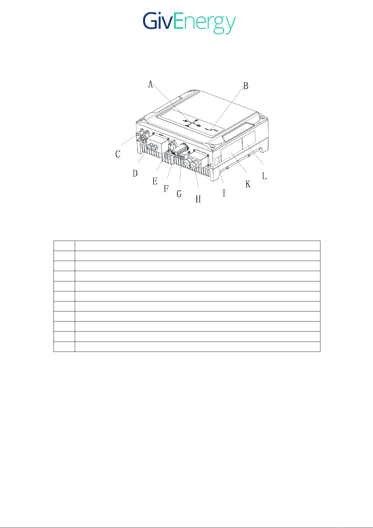
3.1 Inverter Overview........................................................................................................9
3.2 Information of the unit.................................................................................................9
3.3 Storage of Inverter .....................................................................................................10
4 Unpacking............................................................................................................................. 11
5 Installation and Electrical Connection..................................................................................12
5.1 Safety .........................................................................................................................12
5.2 Selecting the installation location ..............................................................................13
5.3 Mounting the Inverter with bracket ...........................................................................17
5.4 Fixed the inverter on the wall ....................................................................................18
5.5 Check Inverter Installation Status..............................................................................19
5.6 Electrical Connection.................................................................................................20
5.6.1 Safety ......................................................................................................................20
5.6.2 System Diagram with Inverter Electrical................................................................20
5.6.3 Connecting to the grid (AC utility).........................................................................22
5. 6.4 Connect to PV Panel ..............................................................................................24
5.6.5 connect to the battery..............................................................................................27
5.6.6 Load monitor connect to the inverter......................................................................28
6 The inverter parameter setting ..............................................................................................30
7 Communications ...................................................................................................................30
7.1 WIFI...........................................................................................................................30
7.2 DMR0 ........................................................................................................................30
8 Start-Up and shut down the inverter.....................................................................................31
8.1 Start-Up the inverter ..................................................................................................31
8.2 Disconnecting the Inverter.........................................................................................31
9 Maintenance and Cleaning....................................................................................................32
9.1 Checking Heat Dissipation ........................................................................................32
9.2 Cleaning the Inverter .................................................................................................32
9.3 Checking the DC switch ............................................................................................32
10 Decommissioning ...............................................................................................................32
10.1 Dismantling the Inverter ..........................................................................................32

3
10.2 Packing the Inverter.................................................................................................33
10.3 Storing the Inverter ..................................................................................................33
10.4 Disposing of the Inverter .........................................................................................33
11 Operating Modes ................................................................................................................34
12 Manufacturer Warranty ......................................................................................................34
13 Technical Data ....................................................................................................................35
14.Contact................................................................................................................................37

4
1 Notes on this manual
1.1 Validity
This manual describes the assembly, installation, commissioning and maintenance of
the hybrid inverter.
This manual does not cover any details concerning equipment connected to the unit
( e.g. PV modules). Information concerning the connected equipment is available from
the manufacturer of the equipment.
1.2 Target Group
1.3 Additional information
Find further information on special topics in the download area.
1.4 Storage of the manuals
The manual and other documents must be stored in a convenient place and be available
at all times. We assume no liability for any damage caused by failure to observe these
instructions.
This manual is for qualified personnel. Qualified personnel have received training and
have demonstrated skills and knowledge in the construction and operation of this
device. Qualified personnel are trained to deal with the dangers and hazards involved
in installing electric devices.

5
1.5 Symbols Used
The following types of safety instructions and general information appear in this
document as described below:
Read the manual!
Danger indicates a hazardous situation which, if not avoided, will result in
death or serious injury.
WARNING indicates a hazardous situation which, if not avoided, could
result in death or serious injury.
CAUTION indicates a hazardous situation which, if not avoided, could
result in minor moderate injury.
Failure to observe a warning indicated in this manual may lead to damage to
property

6
1.6 Markings on this product
Symbol
description
Warning regarding dangerous voltage
The product works with high voltage. All work on the
product must only be performed as described in its
documentation.
Beware of hot surface
The product can become hot during operation. Do
not touch the product during operation.
Observe the operating instructions
Read the product’s documentation before working on
it. Follow all safety precautions and instructions as
described in the documentation.
Point of connection for grounding
protection.
Direct Current (DC)
Alternating Current (AC)
Signals danger due to electrical shock and
indicates the times (5 minutes) to allow after
the inverter has been turned off and
disconnected to ensure safety in any
installation operation.

7
2 Safety and conformity
2.1 Safety Instructions
Danger to life due to lethal voltages!
Lethal voltages are present within the unit and on the power supply lines.
Therefore, only authorized electricians may install and open the unit.
Even when the unit is disconnected, high contact voltages may still be present
within the unit.
Danger of burn injuries due to hot enclosure parts!
During operation, the four sides of the enclosure lid and the heat sink may
become hot.
Only touch the front enclosure lid during operation.
Possible damage to health as a result of the effects of radiation!
In special cases, there may still be interference for the specified application area
despite maintaining standardized emission limit values (e.g. when sensitive
equipment is located at the setup location or when the setup location is near
radio or television receivers). In this case, the operator is obliged to take proper
action to rectify the situation.
Do not stay closer than 20 cm to the inverter for any length of time.
Grounding the PV generator
Comply with the local requirements for grounding the PV modules and the PV
generator. we recommends connecting the generator frame and other
electrically conductive surfaces in a manner which ensures continuous
conduction with ground these in order to have optimal protection of the system
and personnel.

8
Capacitive Discharge Currents
PV modules with large capacities relative to earth, such as thin-film PV
modules with cells on a metallic substrate, may only be used if their coupling
capacity does not exceed 470nF. During feed-in operation, a leakage current
flows from the cells to earth, the size of which depends on the manner in which
the PV modules are installed (e.g. foil on metal roof) and on the weather (rain,
snow). This "normal" leakage current may not exceed 50mA due to the fact that
the inverter would otherwise automatically disconnect
from the electricity grid as a protective measure.
u
DC and AC breaker
Separate the unit securely from the grid and the PV generators, battery using DC
and AC breaker. DC and AC breaker shall be able to disconnect all non-ground
conductors after installation.
u
Grounding the PV modules
The unit is a transformerless inverter. That is why it has no galvanic separation. Do
not ground the DC circuits of the PV modules connected to the unit. Only ground
the mounting frame of the PV modules.
If you connect grounded PV modules to the unit the error message "PV ISO Low".
u
Qualification of Skilled Workers
• Knowledge of how an inverter works and is operated
• Instruction in how to deal with the dangers and risks associated with installing
and using electrical devices and plants
• Training in the installation and commissioning of electrical devices and plants
• Knowledge of all applicable standards and guidelines
• Knowledge and observance of this manual and all safety instructions

9
3 Product Description
3.1 Inverter Overview
3.2 Information of the unit
The unit is bidirectional which applies to the PV system with battery storage. Energy
produced by the PV system is used to optimize self-consumption; excess energy is
used to charge the batteries, and then fed into the public grid when the PV energy is
adequate, When PV energy output is insufficient to support connected loads, the
system automatically get energy from the batteries if battery capacity is sufficient. If
the battery capacity is insufficient to meet own consumption requirements, electricity
will be drawn from the public grid.

10
A
The inverter power flow direction indicator
B
The inverter operation status indicator
C
PV input terminals
D
Battery input terminals and cover
E
PV input switch
F
WIFI com module and USB port
G
BAT._NTC and RS485 communication (BMS com, load monitor com, )
H
AC Output terminals and cover
I
Inverter Serial No.
k
Spec label
L
Warning signals label
3.3 Storage of Inverter
If you want to store the unit in your warehouse, you should choose an appropriate
location to store the inverter.
Ø
The unit must be stored in original package and desiccant must be left in the
package.
Ø
The storage temperature should be always between -25℃and +60℃. And the
storage relative humidity should be always between 0 and 95%.
Note; the battery storage much be according with the battery spec.
Ø
If there are a batch of unit need to be stored, the maximum layers for original

11
carton is four.
4 Unpacking
Thoroughly inspect the packaging upon received. If any damage to the carton is visible,
or if you find that the unit is damaged after unpacking, please notify the shipping
company immediately.
Meanwhile please check the delivery for completeness and for visible external
damage to the unit. If there is anything damaged or missing, please contact your
dealer. Don’t dispose its original package. If you want to transport the unit, it is better
to store the unit into the original package.
Complete delivery should contain as follows:
Item
Name
Quantity
A
Inverter
1
B
Mounting frame
1
C
WIFI
1
D
BAT wire cover
1
E
BMS,RS485 com wire cover
1
F
AC output cover
1
G
Cover screw
14
H
Inverter hold screw
2
I
Mounting frame screw
6
J
Battery input terminal
2

12
5 Installation and Electrical Connection
5.1 Safety
Danger to life due to fire or explosion
Despite careful construction, electrical devices can cause fires.
Do not install the inverter on easily flammable materials and where flammable
materials are stored.
Risk of burns due to hot enclosure parts
Mount the inverter in such a way that it cannot be touched inadvertently.
Ø
All electrical installations shall be done in accordance with the local and
national electrical codes. Do not remove the casing. Inverter contains no
user serviceable parts. Refer servicing to qualified service personnel. all
wiring and electrical installation should be conducted by qualified service
personnel.
Ø
Carefully remove the unit from its packaging and inspect for external
damage. If you find any imperfections, please contact your local dealer.
Ø
Be sure that the inverters are connected to the ground in order to protect
property and personal safety.
Ø
The inverter must only be operated with PV generation. Do not connect any
other source of energy to it.
Ø
Both AC and DC voltage sources are terminated inside the PV
Inverter.Please disconnect these circuits before servicing.
Ø
This unit is designed to feed power to the public power grid (utility)only.
Do not connect this unit to an AC source or generator. Connecting Inverter
to external devices could result in serious damage to your equipment.
Ø
When a photovoltaic panel is exposed to light, it generates a Dc voltage
When connected to this equipment, a photovoltaic panel will charge the DC
link capacitors.
Ø
Energy stored in this equipment’s DC link capacitors presents a risk of
electric shock. Even after the unit is disconnected from the grid and
photovoltaic panels, high voltages may still exist inside the PV-Inverter.

13
Do not remove the casing until at least 5 minutes after disconnecting all
power sources.
Ø
Although designed to meet all safety requirements, some parts and surfaces
of Inverter are still hot during operation. To reduce the risk of injury, do not
touch the heat sink at the back of the PV-Inverter or nearby surfaces while
Inverter is operating.
5.2 Selecting the installation location
Ø
This is guidance for installer to choose a suitable installation location, to
avoid potential damages to device and operators.
Ø
Raintight or wet location hubs that comply with the requirements mentioned
in this installation manual are permitted.
Ø
The unit shall be mounted at least 914 mm (3 feet) above the ground.
Ø
The installation location must be suitable for the inverter's weight and
dimensions for a long period time.
Ø
Select the installation location so that the status display can be easily viewed.
Ø
Do not install the inverter on structures constructed of flammable materials.
Ø
The humidity of the installation location should be 0~95% without
condensation.
Ø
The installation location must safely accessible to get at all times.
Ø
Vertically installation or tilted backwards by max. 15°. and make sure the
connection of inverter must be downwards. Never install horizontal and avoids
forward and sideways tilt.
Ø
Be sure that the inverter is out of the children’s reach.
Ø
Don’t put any things on the inverter. Do not cover the inverter.
Ø
Do not install the inverter near television antenna or any other antennas,
antenna cables.
Ø
Inverter requires adequate cooling space. Providing better ventilation for the
inverter to ensure the heat escape adequately. The ambient temperature should
be below 40°C to ensur e optimum operation. Please make sure the inverter is
installed at the right place,

14
' .

15
Ø
The inverter can’t install to direct sunlight, direct heavy water sources or
infirm locations. We suggest that the inverters should be installed at the
location with some cover or protection。
Ø
Observe the minimum clearances to walls, other inverters or objects as shown
in the diagram below in order to guarantee sufficient heat dissipation.
Direction
Min. clearance (cm)
above
30
below
50
sides
30
front
30

16
Ambient dimensions of one inverter
Ambient dimensions of a series inverters
Ø
There must be sufficient clearance between the individual inverters to ensure
that the cooling air of the adjacent inverter is not taken in.
Ø
If necessary, increase the clearance spaces and make sure there is enough
fresh air supply to ensure sufficient cooling of the inverters.

17
5.3 Mounting the Inverter with bracket
Ø
The dimension of bracket as follow:
Ø
Using the mounting frame as a template, drill holes as illustrated in image.
Fix the mounting frame as the figure shows. Do not make the screws to be flush
to the wall. Instead, leave 2 to 4mm exposed.
In order to avoid electrical shock or other injury, inspect existing electronic or
plumbing installations before drilling holes.

18
5.4 Fixed the inverter on the wall
Ø
Raise the inverter a little higher than the bracket. Considered the weight of
them. During the process please maintain the balance of the inverter.
Hang the inverter on the bracket through the match hooks on bracket.
Falling equipment can cause serious or even fatal injury, never mount the inverter on
the bracket unless you are sure that the mounting frame is really firmly mounted on the
wall after carefully checking.

19
Ø
After confirming the inverter is fixed reliably, fasten four M6 safety-lock
sockets head cap screws on the left and right side firmly to prevent the inverter
from being lifted off the bracket.
5.5 Check Inverter Installation Status
Ø
Check the upper straps of inverter and ensure it fits on to the bracket.
Ø
Check the secure mounting of the inverter by trying to raise it from the
bottom.The inverter should remain firmly attached.
Ø
Choose a strong mounting wall to prevent vibrations while inverter
operating.

20
5.6 Electrical Connection
5.6.1 Safety
Danger to life due to lethal voltages!
High voltages which may cause electric shocks are present in the conductive
parts of the inverter. Prior to performing any work on the inverter, disconnect
the inverter on the AC side, PV side, battery side..
Do not reverse input of battery! That will be destroyed the inverter!
Danger of damage to electronic components due to electrostatic discharge.
Take appropriate ESD precautions when replacing and installing the inverter.
Grounding
Before connecting the power cables, you must connect ground wire first.
5.6.2 System Diagram with Inverter Electrical
This manual suits for next models
2
Table of contents
Other GivEnergy Inverter manuals
Popular Inverter manuals by other brands

Hitachi
Hitachi SJ100DN DeviceNet Series Addendum Instruction manual addendum

SunSynk
SunSynk SUN-25K-SG01HP3-EU-BM2 Installer manual

SSI
SSI MPG-1 Installation instruction sheet

Volpi Tecno Energia
Volpi Tecno Energia PAGURO 12500 owner's manual

Pulsar
Pulsar PG1202S Operator's manual

SMA Solar Technology
SMA Solar Technology Sunny Boy 2500 user manual