REITZ MEE User manual

02/2005
MEE_englisch.doc
Operating Manual
Single stage radial fan
Model MEE
KONRAD REITZ VENTILATOREN GmbH & Co. KG
Konrad Reitz-Straße 1
D-37671 Höxter - Albaxen (Germany)
Telephone +49 (0) 52 71 / 964-000 · Telefax +49 (0) 52 71 / 964-119
Email: [email protected]

Table of contents
0.1
1. Safety
1.1 General ..........................................................................................................1.1
1.2 Description of symbols and pictograms .........................................................1.2
1.3 Start-up ..........................................................................................................1.2
1.4 Servicing ........................................................................................................1.3
1.5 Cleaning.........................................................................................................1.3
1.6 Electrical safety..............................................................................................1.4
1.7 Description of labels and plates.....................................................................1.5
2. Application
2.1 Design conditions...........................................................................................2.1
2.2 Warranty.........................................................................................................2.1
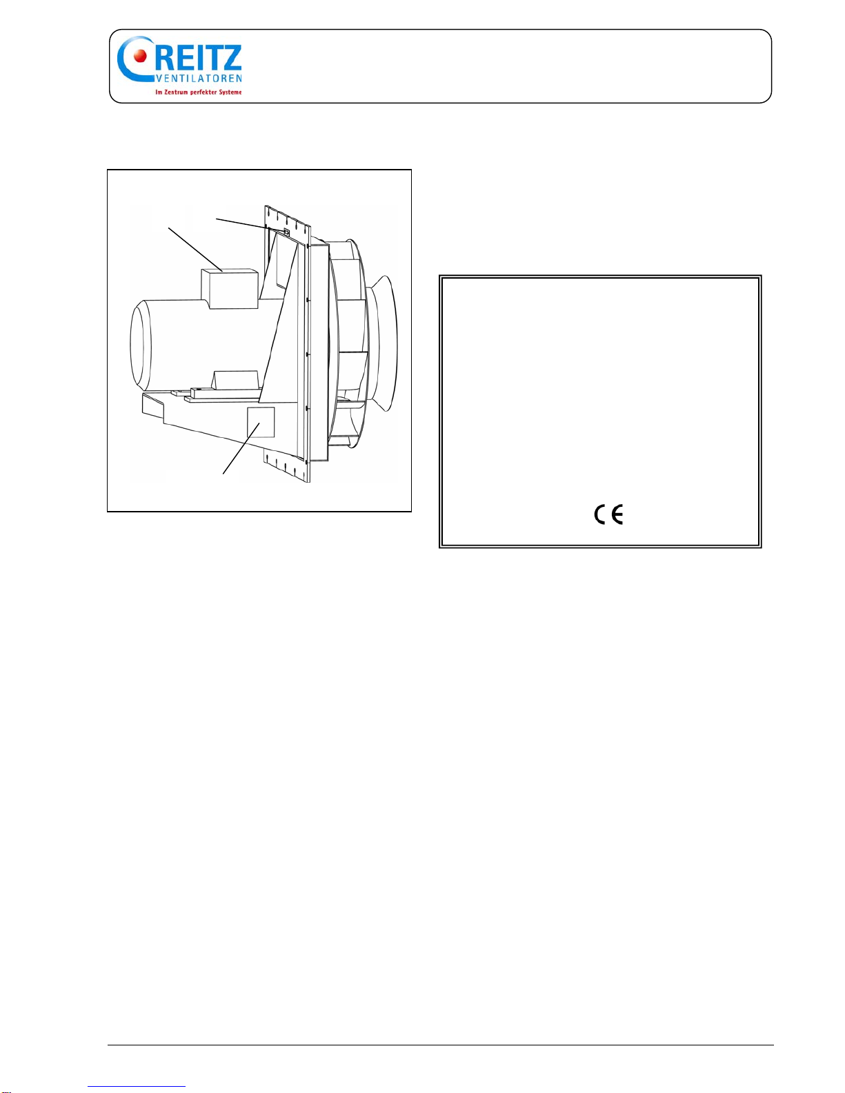
3. Description
3.1 Design............................................................................................................3.1
3.2 Options...........................................................................................................3.1
4. Assembly and installation
4.1 Scope of supplies...........................................................................................4.1
4.2 Transport........................................................................................................4.1
4.3.1 Storage...........................................................................................................4.2
4.3.2 Stand-by operation.........................................................................................4.2
4.4 Installation site ...............................................................................................4.2
4.5 Electrical connection......................................................................................4.3
4.6 Inspection.......................................................................................................4.4
4.6.1 Mechanical testing .........................................................................................4.4
4.6.2 Electrical testing.............................................................................................4.4
5. Start-up
5.1 Putting the fan into operation.........................................................................5.1
5.2 Putting the fan out of operation......................................................................5.1
5.3 Transient behaviour .......................................................................................5.2
5.3.1 General ..........................................................................................................5.2
5.3.2 Direct starting.................................................................................................5.2
5.3.3 Star-delta starting...........................................................................................5.2
6. Care and maintenance
6.1 Lubrication......................................................................................................6.1
6.1.1 Drive motor.....................................................................................................6.1
6.1.2 Shaft seal.......................................................................................................6.1
6.2 Troubleshooting .............................................................................................6.2
6.3 Queries/Sending-out of fitter ..........................................................................6.4
Technical data see data sheet!

1 Safety
1.1
1.1 General
The fan meets the technical safety standards
applicable in the EC at the time of delivery. The
rules and regulations for the prevention of accidents
applicable at the time of delivery were taken into
account in the fan design.
The technical design meets DIN 24166 standard
“Technical delivery conditions for fans”.
It is not allowed to modify the original condition of
the fan without the approval of Reitz. The warranty
expires when parts other than original Reitz spare
parts and/or purchased parts not corresponding to
the original parts are used.
Any variation or repair work has to comply with the
brochure ”Safety instructions for the application of
Reitz products”. Please request the brochure from
us if it has not yet been supplied.
The operating manual and any required
supplementary manuals must be available to the
operator.
It must be ensured that fans which are installed at
high levels can only be reached via stages
especially installed for this purpose.
All devices and installations provided to prevent
noxious substances from escaping must be checked
before the fan is put into operation.
Do not bypass, loosen of remove guards
and protective devices.
Do not open inspection ports and/or other openings
when the fan is in operation.

1 Safety
1.2
1.2 Description of symbols and
pictograms
This symbol draws your attention to
dangerous situations. The operation
concerned may endanger persons and
cause injuries.
This symbol is used to indicate that the
work must be carried out by a trained and
qualified electrician.
This symbol is followed by supplementary
information.
1.3 Start-up
The fan may only be put into operation (also for
testing) when the inlet and discharge ports are
provided with suitable guards/plate shutters or when
the fan is ducted.
Before the fan is started the housing and all duct
work connected to it must be checked. They must
be dry and free of screws, bolts, tools and other
foreign substances.
Disregarding the above instructions may
cause accidents and destroy the fan.
Observe the safety regulations for electrical
machines and equipment.
(→Electrical safety)

1 Safety
1.3
1.4 Servicing
The fan may only be serviced when the electrical
system is dead, i.e.:
— turn off the electrical machines and ensure
that they cannot be switched on again,
— wait until the rotor has come to a standstill,
— remove the motor fuse,
— disconnect the power supply cable for the
motor.
After servicing all guards and protective devices
must be installed and the fan must be ducted again.
All bolts and nuts must be tightened. Close all
inspection openings and tighten the bolts and nuts.
The fan can then be put into operation again.
1.5 Cleaning
Do not clean moving parts when the fan is in
operation!
Before cleaning the fan must be put out of
operation. Ensure that the fan cannot be switched
on again accidentally. Only use suitable detergents
and cleaning materials.
Remove any dirt wiped off the impeller from the fan
housing.
If material is sticking to the impeller or the
impeller is worn, the fan may be seriously
damaged by unbalance. It is therefore
recommended to clean and check the fan
for unusual vibrations at regular intervals.

1 Safety
1.4
1.6 Electrical safety
The user has to ensure that the fan is only
connected and serviced by a qualified electrician in
accordance with the rules and regulations applying
to electrical equipment.
The user must also ensure that the fan is operated
in accordance with electro-technical rules and
regulations.
Do not touch/work on live parts.
— Interrupt the power supply to the fan and
use mechanical means to ensure that power
supply cannot be switched on again.
— Use a voltage tester to check that the circuit
is dead.
— Connect and short the work site to earth.
— Only use the fuses indicated in the electric
circuit diagram.
— Check the condition of the visible cables
before the fan is started.
— Replace damaged cables.
Damaged and/or defective electrical equipment
must be repaired or replaced immediately. If the
damaged equipment represents a risk, the fan may
not be put into operation before the defect is
repaired.

1 Safety
1.5
1.7 Description of labels and
plates
The following plates are attached to the fan:
1. Nameplate
The nameplate indicates:
FAN /
Type/ ................................…......
Serial No. / Year of constr. ............................ / ...….....
Com. - No. / ....................................…..
Fan data at a density of ρA = 1,2 kg/m3
Inlet temperature ϑ................................ °C
Volumetric flow V1................................ m3/min
Total press. increase Δpt2................................ daPa
Total press. increase Δpt1................................ daPa
Shaft rating PW ................................ kW
Speed n................................ 1/min
Working temperature ϑ ................................ °C
Further data are indicated on the fan data
sheet of the fan.
2. Arrow showing the sense of rotation of the
impeller.
3. Company emblem
4. CE sign
5. Motor nameplate
1, 3, 4
25

2 Determined use
2.1
2.1 Design conditions
The fan is designed, tested and delivered in
accordance with the instructions given in the order.
The instructions indicated in the order have been
entered on the fan data sheet of the fan. It is not
permitted to change the conditions under which the
fan is to be used (e.g. another medium). These
conditions are also entered on the fan data sheet.
2.2 Warranty
The warranted data refer to single values and
testing conditions in accordance with the applicable
DIN standards and/or codes of practice. The special
characteristics and local conditions of the plant in
which the fan is to be incorporated must be taken
into account by the plant designer and/or planning
engineer when ordering.
The data has to be based on the actual operating
conditions.

3 Description
3.1
3.1 Design
The model MEE fan is a welded single-stage radial
fan. It is driven directly by the motor shaft on which
the impeller is mounted.
For special designs please note the
information given on the fan data sheet.
The shaft passage is sealed with a graphite cord.
This seal is not completely tight. For
special shaft seals please refer to the
information provided in the annex.
3.2 Options
Accessories are available to adapt the fan to certain
specific plant characteristics.
For additional information see (→Annex).
1 – inlet nozzle 5 – shaft seal
2 – impeller 6 – pedestal
3 – shaft seal 7 – heat insulation case
4 – heat flinger (cooling disk)
1
2
3
4
7
5 6

4 Assemblage
4.1
4.1 Scope of supplies
When delivered the fan and accessories must be
checked for damage caused by damaged packing.
Immediately report any transport damage to the
forwarding agent, insurance company and
manufacturer.
Check that everything indicated on the delivery note
has been delivered.
In all other respects please refer to our terms and
conditions for sales and delivery.
4.2 Transport
Only transport the fan with transport facilities which
are appropriate for the conditions on the site where
the fan is to be installed.
Observe the applicable rules and re-
gulations for the prevention of accidents.
For lifting and transporting the fan only ropes and/or
fork lift trucks with a sufficient lifting capacity may be
used.
Only attach ropes to the fastening plates especially
provided for lifting the fan.
Do not sling lifting ropes to the impeller or
the motor. Do not use the motor lifting lug
for transport.
Warranty claims or claims for compensation for any
damage caused by the use of unsuitable means of
transport or caused by improper handling will not be
accepted.

4 Assemblage
4.2
4.3.1Storage
If the fan is not installed and/or put into operation
immediately it must be stored in a dry place which is
free of vibrations.
In case of long-term storage please note the storage
and preservation instructions for motors.
4.3.2Stand-by operation
In case of long-term standstill periods, please note
the relevant instructions for the storage of motors.
4.4 Installation site
The installation site must be level and have a
sufficient load bearing capacity. There must be
enough room for assembly and maintenance work.
The impeller must be easily accessible.

4 Assemblage
4.3
4.5 Electrical connection
The fan may only be connected up to the
electrical system by a qualified electrician.
The drive motors are usually installed in the
manufacturing works. The works warranty
does not apply if the customer installs the
motors.
[→Chap. Electrical safety ]
The operating instructions of the motor
manufacturers must be observed.
The motor is connected in accordance with the
circuit diagram inside the terminal box (1). The
customer has to check that his power network and
the switchgear and monitoring devices are
sufficiently dimensioned to cope with the transient
behaviour and current peaks. It must be ensured
that the supply of cooling air to the electric motor is
not hindered.
— The power supply cable for the fan must be
installed in accordance with VDE regulations
or any locally applicable legal stipulations.
— Compare the local mains voltage with the
voltage indicated on the rating plate (2) of
the fan.
— Connect the fan as shown on the circuit
diagram inside the terminal box (1).
— Earth the fan in accordance with the
regulations issued by the local power supply
company.
— Check the speed and sense of rotation.
— Check the transient behaviour and starting
time.
—Provide for a motor protection system.

4 Assemblage
4.4
4.6 Inspection
4.6.1Mechanical testing
Check the fan after it has been assembled and
installed.
— Check the attachment of the fan to the
foundation.
— Check if the impeller rotates freely (turn it
with the hand).
— Remove any foreign objects from the fan
housing.
— Check all screw couplings and bolted
connections.
— Check all connections to duct work.
4.6.2Electrical testing
The electrical system of the fan may only
be tested by a qualified electrician.
— Check the operating voltage.
— Check the earthing.
— Check the size of the fuses.
If the fan is not put into operation immediately after
it has been assembled and installed, it must be
secured against unauthorized use and covered with
a tarpaulin.

5 Start-up
5.1
5.1 Putting the fan into operation
The fan may only be put into operation by
qualified and skilled staff. Before the fan is
put into operation the staff must check that
the fan is in good working order.
The rules and regulations for putting
electrical machines into operation must be
observed.
— Check the safety systems.
— Close the dampers (if provided).
— Switch on the master controller.
— Switch on the fan.
The fan may only be switched on when it is
ducted and when it is certain that there will
be a sufficient plant resistance after the fan
motor has reached its full operating speed.
— Check the sense of rotation of the motor
when the fan is started up for the first time
(the motor must rotate in the direction
indicated by the arrow).
— Check the power consumption. The
maximum permissible power consumption
may not be exceeded.
5.2. Putting the fan out of operation
— Switch off the fan.
—Turn master controller to “OFF” and secure it
against unauthorized use.

5 Start-up
5.2
5.3 Transient behaviour
5.3.1General
The fan can only be started when a
sufficiently high moment of acceleration is
available form the moment it is started up
to the moment when nominal speed is
reached.
It is recommended to start the fan with the damper
closed.
The customer has to check that his power
network, switchgear, monitoring devices (if
available) and cable cross sections are
dimensioned to cope with the transient
behaviour and current peaks.
5.3.2Direct starting
Direct starting of the fan motor not only causes a
high starting torque but also a high starting current.
During starting the starting current may be 6 to 8
times as high as the nominal current (depending on
the type of rotor).
This high power input must be taken into account
when the fuse sizes are determined.
The connecting frequency of the electric motors
must not exceed six activations per hour. The
instructions of the motor manufacturer are to be
observed. Please contact the motor manufacturer
for further information if necessary.
5.3.3 Star-delta starting
During star-delta starting the drive motor only
provides for 1/3 of the starting torque in the star
connection. At a certain starting speed the load
moment of the fan exceeds the starting torque of the
motor. The motor does not accelerate. At this point
the motor has to be changed over to the delta
connection. The current peak which is then obtained
is clearly lower than the one occurring during direct
starting.
MmMotormoment
MLLoadmoment
Mbm Mean acclerating moment
n Speed
Designation of Mean accelerating moment
change over point

6 Care and Maintenance
6.1
6.1. Lubrication
The fan must be checked at regular
intervals (depending on the operating
conditions).
6.1.1Drive motor
The motor must be serviced in accordance with the
motor’s lubricating instructions.
6.1.2Shaft seal
Lubricate the seal once a month.
(use an oil can to pour a small amount of machine
oil in the gap between the seal and shaft).
If a special seal is used, please refer to the
lubrication instructions in the annex.
impeller hub
sealing cord
heat flinger
motor journal

6 Care and Maintenance
6.2
6.2 Troubleshooting
Malfunction Possible cause Action
Unsteady operation of fan. Material sticking to impeller
blades. Carefully clean impeller.
Worn impeller. Replace impeller.
Impeller deformed by heat. Replace impeller.
Medium escapes at the shaft
seal. Seal is faulty or worn. Replace seal.
Fan produces a grinding noise. Impeller rubs against inlet
nozzle. Loosen housing cover an re-
align, check and correct duct
work if necessary.
Motor noise
Check if bearings are damaged
and replace bearings if
necessary.
The power input indicated on the
rating plate is constantly
exceeded.
Air volume too much. Reduce air volume using a
damper until the permissible
power input is reached.
Different speed with 60 Hz. Check frequency.

6 Care and Maintenance
6.3
Troubleshooting (cont’d)
Malfunction Possible cause Action
Fan does not accelerate. Improper connection of drive
motor. Check connection.
Motor does not change from star
to delta connection. Shorten change-over time
from star to delta.
Fan operates against insufficient
plant resistance. Close dampers or install
additional plate shutters.
Motor protection system is not
strong enough. Cable cross section and
protective system must withstand
starting current during
acceleration.
Starting time is too long. Close dampers, check starting
torque of MA/MN motor.
Faulty drive motor. Check motor and replace if
necessary.
Motor too warm due to extensive
operating frequency Run the fan in continuous
operation and control the flow
with dampers or variable speed
control
Starting current too high.. Wrong voltage.
Provide star-delta starting,
local mains not strong enough.

6 Care and Maintenance
6.4
6.3 Queries/Sending-out of fitter
If you have any queries, want to order spare parts or
have a fitter sent out to you, your request should
include the following details:
— Serial No. of the fan, (5 or 6-digit number
indicated on the fan data sheet or on the
nameplate).
— Exact address of the user.
— Name of the person our fitter should get in
touch with.
— If possible a description of the malfunctions
(visible/audible). An exact description will
allow us to help you more quickly and
efficiently. Information sent out by FAX will
be very much appreciated.
Please contact:
KONRAD REITZ Ventilatoren
GmbH & Co. KG
Montageabteilung
P.O. Box 10 05 53
D-37655 HÖXTER - Albaxen
Telephone: +49 (0) 52 71 / 964-000
Telefax: +49 (0) 52 71 / 964-119
Table of contents
Other REITZ Fan manuals
Popular Fan manuals by other brands

Thermaltake
Thermaltake Pure 14 ARGB Sync installation guide

Delta Electronics
Delta Electronics AHB1748VHG Dimensions and installation information

Titon
Titon CME3Q+ Fault Finding

Turn of the century
Turn of the century Elise Installation and operation instruction

Panasonic
Panasonic F-48MZ2 Operating and installation instructions

Hinkley
Hinkley CROFT instruction manual