Relay PadPuls M1 User manual

PadPuls M1
1-channel M-Bus
pulse converter
for reed signals
User Manual

User Manual PadPuls PadPuls M1 · 10/2018 · VERSION 1.4
2
PadPuls M1
Table of content
1 Functional description...............................................................................................................3
2 Installation and startup..............................................................................................................4
2.1 Mounting the case ...........................................................................................................4
2.2 Opening the case.............................................................................................................4
2.3 Connecting ......................................................................................................................4
3 Parameterization using MBCONF.............................................................................................6
3.1 Installation .......................................................................................................................6
3.2 Operation.........................................................................................................................6
3.3 Sheet Info........................................................................................................................7
3.4 Sheet M1.......................................................................................................................10
4 M-Bus Telegrams....................................................................................................................13
5 Technical Data........................................................................................................................15
5.1 General..........................................................................................................................15
5.2 M-Bus Interface .............................................................................................................15
5.3 Power Supply ................................................................................................................15
5.4 Reed-Input.....................................................................................................................16
5.5 Requirements to contacts of pulse generators ..............................................................16
5.6 Ordering information......................................................................................................16
This documentation is valid from M-Bus generation: $09
© Relay GmbH 2018
www.relay.de

User Manual PadPuls PadPuls M1 · 10/2018 · VERSION 1.4
3
PadPuls M1
1 Functional description
The PadPuls M1 adapts consumption measuring instruments, such as, electricity, gas or water
meters to the M-Bus system. The meters that are to be adapted must have a floating pulse
output. The user can configure the PadPuls M1 with the MBCONF program so that the counted
impulses are converted to units such as kWh, m3, J and so on. With its user interface the
configuration of MBCONF is very easy.
When connected to the M-Bus the PadPuls M1 is powered by the bus. A built-in battery ensures
that metering continues even if the M-Bus fails for longer than the normal calibration time of the
water meter or heat counter. The battery also ensures that the meter readings and the
configuration data is maintained in RAM. Therefore the battery jumper should be plugged in at
all times. The jumper serves only to disconnect the battery from the circuitry if the battery needs
to be replaced.
Device data can be protected against unauthorized configuration. The PadPuls M1 can be
switched to protection mode with a special M-Bus telegram. In this operating mode, subsequent
changes to device parameters cannot be made. The protection mode can then only be disabled
by opening the sealable housing and pressing the unprotect pushbutton.

User Manual PadPuls PadPuls M1 · 10/2018 · VERSION 1.4
4
PadPuls M1
2 Installation and startup
2.1 Mounting the case
The housing is fixed to the wall with two
screws, which are screwed diagonally
through the holes marked with “wall”. he
heads of the screws should be
maximum 6 mm in diameter so that the
cover is not screwed as well.
2.2 Opening the case
To deactivate the write protection or connect the cables the housing cover can be opened by
removing the metal screws above at the left and below at the right. The unprotect pushbutton is
then accessible from outside; the unit is unprotected by pressing this button.
Use a suitable adhesive seal to prevent unnoticed opening of the housing.
2.3 Connecting
The following drawing shows a typical application of the PadPuls M1:
M-Bus Master PadPuls M1 pulse generator (blue)
46
67
80
98
88
D= 6
D= 6
D= 5
D= 5
Housing
Housing
Wall
Wall
all dimensions in mm

User Manual PadPuls PadPuls M1 · 10/2018 · VERSION 1.4
5
PadPuls M1
After opening the housing please lead the M-Bus cable through the left cable gland of the cover
and connect the cable to the left terminal. Then do the same with the cable of the pulse
generator (right side). Please connect an optional shielding to the terminal labelled with „shield“.
Connect the shielding only to the PadPuls.
•Impulse devices with floating contacts (reed contacts) are connected to the terminals
marked with “pulse” using any polarity. If cable shielding is available, it can be wired single-
sided to the terminal marked with “shield”.
•Impulse devices with optocouplers or electrically isolated transistor outputs must be
connected to the “pulse” with the correct polarity. The left-hand terminal is the positive
connection and the middle terminal the negative connection.
The following graphic shows the position of the terminals and the button:
Attention: The battery jumper is plugged in at the factory and should not be removed as the
PadPuls M1 will otherwise lose configuration. In this case, a new configuration including
programming of the ID is necessary.
lithium battery 3,0V / 1800 mAh
jumper
battery
terminal
M-BUS
unprotect
key
terminal
pulse
shield
+-

User Manual PadPuls PadPuls M1 · 10/2018 · VERSION 1.4
6
PadPuls M1
3 Parameterization using MBCONF
The device is supplied with a basic configuration (address 0, unprotected) and must be adapted
by the customer to the respective installation. Parameterization requires the MBCONF program.
You will find the free software on our CD "Tools & Docs" and for download on our homepage
www.relay.de.
3.1 Installation
The software MBCONF for configuration of the pulse adaptor is a 32-bit application, which can
be executed on IBM-PC compatible computers under the operating systems Windows 10 / 8.1 /
7 / XP / 2000 / 98 / 95. The desktop PC or laptop must have a free serial RS232C interface to
connect the M-Bus level converter. You can alternatively use an USB or Ethernet to M-Bus level
converter with a driver for a virtual serial port. We recommend our service tool Micro-Master
USB (art.no. MR003USB). The PadPuls M1 to be parameterized must be connected directly (i.e.
as only M-Bus device) to the M-Bus output of the level converter.
Please run the file “MBCONF_SETUP.EXE” from Windows Explorer or via “Start – Execute” to
install the software. Subsequently you select the language of the installation procedure. The
setup software can create a program group and a link on the desktop on demand. You can then
execute both versions for German and English language either from start menu or desktop.
3.2 Operation
After program start the user operates the software according to the Windows conventions with
the mouse or the keyboard. If you stay with the mouse on a button or an input field, then a hint
to its function appears. Light-grey fields and boxes cannot be edited.
All input fields and buttons have an underlined letter. The function can be activated by
simultaneous pressing of the keys [ALT] and the respective letter. Within dialogs the cursor can
be moved with the keys [TAB] or [SHIFT] [TAB] forward and backword.
[SPACE] activates or deactivates selection boxes. Multiple selection boxes (arrow at the right
edge) can be activated with []. The user then selects an entry with [] and []. By pressing
[RETURN] the selected entry is taken over. With [ESC] the selection box is left without transfer.
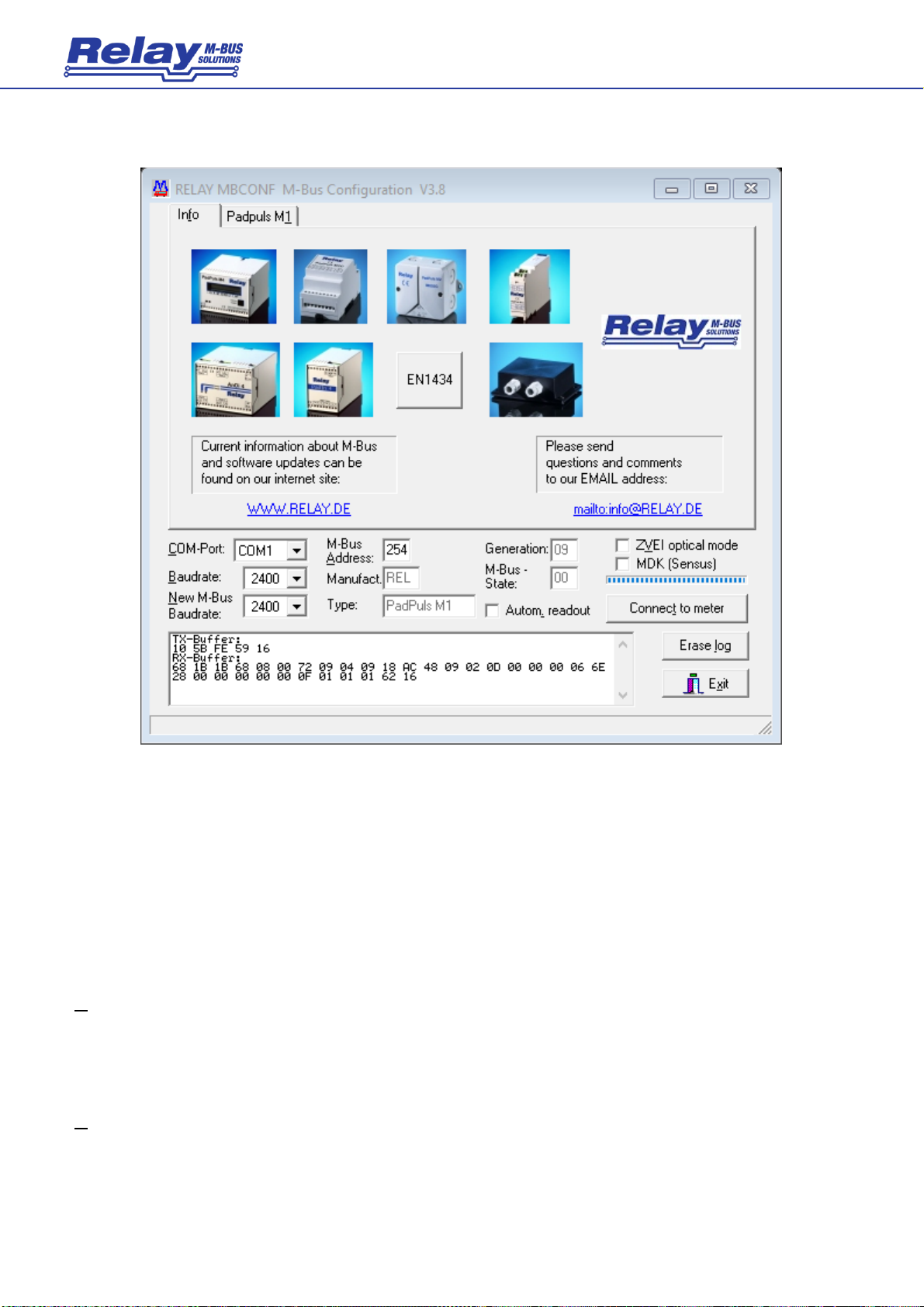
The program is arranged as a sheet system. The sheet “Info” contains general options of the
communication with the M-Bus device to be configured. In this sheet the user can select the
serial port of the PC, the baudrate of the PC, the baudrate of the M-Bus device and the M-Bus
primary address which is used for communication. After a successful connection with the M-Bus
device, further manufacturer information is shown in the sheet “Info” and additional device-
specific sheets are displayed.

User Manual PadPuls PadPuls M1 · 10/2018 · VERSION 1.4
7
PadPuls M1
3.3 Sheet Info
This sheet shows some photos of supported M-Bus devices from the product range of the Relay
GmbH, the PadMess GmbH and further manufacturers. Here are also links to our Internet page,
from which the current version of the program can be downloaded, and to the email address for
criticism and suggestions to the program.
The lower third of this card is likewise visible in every other card. Here the following input fields
and buttons are always attainable:
COM-Port
is the serial port of the PC to which the M-Bus level converter is
connected. The selected port will be saved in an INI file and will be
restored on startup. Therefore the COM-Port has to be configured only
once.
Baudrate
is the transmission speed of the serial port of the PC used for
parameterization. Possible selections for this used M-Bus baudrate are
300, 2400 or 9600 baud. Attention: Baudrates of more than 2400 baud are
not supported by all M-Bus level converters which are available on the

User Manual PadPuls PadPuls M1 · 10/2018 · VERSION 1.4
8
PadPuls M1
market! The selected baudrate must be identical to the baudrate of the
M-Bus device. (see: “New M-Bus Baudrate”). The PadPuls M1 supports all
three baudrates.
New M-Bus
Baudrate
allows reprogramming the baudrate of the M-Bus device. The new
baudrate is sent to the M-Bus device after a change in the appropriate
selection box. If the M-Bus slave accepts this command, it acknowledges
the telegram with the single character „$E5“ ($ for hexadecimal notation)
using the old baudrate. Afterwards the device switches to the new
baudrate. This button is not needed for the PadPuls M1, because it
automatically detects the baudrate used by the master.
M-Bus Address
is the primary address of the connected M-Bus slave. In a direct
connection with only one slave you can use the broadcast address 254.
Using this address every M-Bus device must answer regardless of its own
address.
Connect
to meter
is used to request data from the slave. The type of device is then
automatically recognized. The items “Manufact.”, “Generation”, “Type” and
“M-Bus State” will then be refreshed. New sheets are generated
depending on manufacturer and type of the M-Bus device. A single sheet
appears in case of PadPuls M1.
Manufact.
is an item that shows the 3-letter manufacturer code after successful
reading (“Connect to meter”). This item is read only.
Generation
shows the revision connected M-Bus device. This item is read only.
Type
shows the type (here: PadPuls M1) of the connected device. This item is
read only.
M-Bus State
shows the M-Bus state of the connected device. This item is read only.
ZVEI optical
mode
if this option is activated, devices with an optical interface and M-Bus
protocol according to EN 1434-3 can be read and programmed using an
optical reading head.
MDK (Sensus)
This switch activates the readout with an MDK from Sensus.
Autom. readout
if this option is activated, the software always reads the data after writing
(useful for checking the correct programming).

User Manual PadPuls PadPuls M1 · 10/2018 · VERSION 1.4
9
PadPuls M1
Log-Window
The so-called log window is always visible. All M-Bus communication steps are logged in this
window. Data is displayed in hexadecimal notation. It is possible to mark outputs in the log
window and copy them with the keys “CTRL-C” to the windows clipboard. The data can then
easily be imported to any text editor for documentation. As soon as the maximum storage
capacity of the window is achieved, no more data is logged. If you want to keep on logging, you
have to delete the logged data.
The following buttons are also always visible:
Erase log
clears all outputs inside the log window.
Exit
terminates the program and stores the current setting of serial port
(port no.) into the INI file
.

User Manual PadPuls PadPuls M1 · 10/2018 · VERSION 1.4
10
PadPuls M1
3.4 Sheet M1
This sheet shows the current settings and values of the PadPuls M1. The following input boxes
and buttons are used to change the parameters of the pulse adapter:
Prim. address
is the primary M-Bus address of the selected device. Values between 1 and
250 can be entered in this field for new assignment of the address. After
pressing the “Write” button the software programs this primary address and
further variable settings on this sheet into the M-Bus device.
ID (sec. adr.)
is the 8-digit M-Bus ID (identification no.), which is also used for secondary
addressing of this port.
Pre-programmed ID = YYMM + last 4 digits of serial no.
e.g. ser.no. = 15005, production date = Nov. 2017 (1711) →ID = 17115005
Fabric no.
is not used for the PadPuls M1.
Medium
describes the measured medium of the connected meter. Examples: Oil,

User Manual PadPuls PadPuls M1 · 10/2018 · VERSION 1.4
11
PadPuls M1
Water, Heat, Electricity
Multiplicator is the pulse increment (multiplicator) of the connected meter. For each
registered pulse the device adds “multiplicator” to the counter. The
numerator can take values between 0 (no counting) and 255, the
denominator between 1 and 255.
Unit is the physical unit of the counter and of the pulse increment. All proper
units including variants with power of ten, from the DIN EN 13757-3 are
offered in the selection list. Examples: m3, kWh, MJ
Counter is the accumulated counter. It has to be related to the unit mentioned
above. The 5 byte binary type counter can be programmed equal to the
counter of the connected meter in a range of 0 to 1x10¹² or in detail
1.099.511.627.775 ( = 00 FF FF FF FF FF hex.).
State shows the M-Bus state in hexadecimal notation.
Write protection is marked, if the device is protected against programming. Then you cannot
configure the adapter. The protection can be removed after opening the
sealable front cover of the housing and pressing the “Unprotect” pushbutton.
Permanent Error is not used for the PadPuls M1.
Write protect transmits a command to the PadPuls M1 to activate write protection. The
PadPuls then allows no further configuration. It is protected against
unnoticed manipulation.
Read reads the M-Bus device and refreshes the data on the selected sheet.
Write sends the current options to the pulse converter, which stores this data into
the battery buffered memory. The PadPuls M1 changes the options only if
the write protection is deactivated. It is recommended to read and check the
data after writing.

User Manual PadPuls PadPuls M1 · 10/2018 · VERSION 1.4
12
PadPuls M1
Notes:
1. Please first press the button „Connect to meter“ after connecting a new M-Bus device.
Afterwards all sheets are refreshed.
2. Examples for configuration of pulse increment and unit:
•Water meter with counter = 45120 l and 1 Pulse = 10 l:
Choice 1: Unit = 10 l, Multiplicator = 1 / 1, Counter = 4512 ( x 10 l)
Choice 2: Unit = 1 l, Multiplicator = 10 / 1, Counter = 45120 ( x 1 l)
•Electricity meter with counter = 78346 kWh and 64 pulses / kWh:
Choice: Unit = 1kWh, Multiplicator = 1 / 64, Counter = 78346 ( x 1kWh)
•Electricity meter with counter = 112,345 kWh and 1000 pulses / kWh:
Choice: Unit = 1Wh, Multiplicator = 1 / 1, Counter = 1123454 ( x 0,001Wh)

User Manual PadPuls PadPuls M1 · 10/2018 · VERSION 1.4
13
PadPuls M1
4 M-Bus Telegrams
1) General
•Communications according to EN13757-2 and -3
•Transmission rates 300, 2400 and 9600 Bd with auto-baud detect
•Primary and secondary addressing with wild cards
•SND_NKE / E5, SND_UD / E5, REQ_UD2 / RSP_UD is supported
2) Definitions
•All values are specified in hexadecimal
•Empty fields in the “Contents” line are variable
•Index 1 designates the least-significant byte in fields containing several bytes
3) RSP_UD Telegram
Byte
1
2
3
4
5
6
7
8
9
10
11
12
13
Name
Start
Length
Length
Start
C
A
CI
ID1
ID2
ID3
ID4
MAN1
MAN2
Inhalt
68
1B
1B
68
08
72
AC
48
Byte
14
15
16
17
18
19
20
21
22
23
24
25
26
Name
GEN
MED
TC
Status
SIG1
SIG2
DIF
VIF
Count1
Count2
Count3
Count4
Count5
Inhalt
00 / 80
00
00
06
Byte
27
28
29
30
31
32
33
Name
Count6
Spez.
Index
Numerator
Denominator
CS
Stop
Variable
00
0F
01
16
Notes:
•Manufacturer MAN = “REL” (48AC)
•Generation GEN (at this time $09, reserved range from $01 to $0F)
•Status bit 7 (MSB): 1 →write protection set
0 →write protection removed
•VIF: Set by the user; VIF = unit with decimal power (MSB not set)
•Count: Meter reading (most-significant byte = Count6 always zero)
•Numerator / Denominator: Impulse value (increment in multiples of the VIF per impulse):
1 Pulse =
Numerator
Denominator
•VIF

User Manual PadPuls PadPuls M1 · 10/2018 · VERSION 1.4
14
PadPuls M1
4) Configuration Telegram
Byte
1
2
3
4
5
6
7
8
9
10
11
12
13
Name
Start
Length
Length
Start
C
A
CI
DIF1
VIF1
PAdr
DIF2
VIF2
ID1
Inhalt
68
1C
1C
68
53
51
01
7A
07
79
Byte
14
15
16
17
18
19
20
21
22
23
24
25
26
Name
ID2
ID3
ID4
MAN1
MAN2
GEN
MED
DIF3
VIF3
Count1
Count2
Count3
Count4
Inhalt
06
Byte
27
28
29
30
31
32
33
34
Name
Count5
Count6
Spez.
Index
Numerator
Denominator
CS
Stop
Inhalt
00
0F
01
16
Notes:
•Variables to be configured can only be changed when the write protection is not set
•Grey fields can be altered:
•PAdr = Address (range 0–250)
•ID = ID number (BCD)
•MED = Medium
•VIF3 = Unit and decimal power of the meter reading (MSB = 0)
•Count = Pulse count (5 bytes binary, Count6 is always 00h)
•Meter / denominator: impulse value (range 1–255 each)
•Miscellaneous fields (MAN and GEN are ignored)
•ID, MAN, GEN and MED are coded as in the fixed header of the variable data structure from
EN13757-3
•The data block “Protect index denominator numerator” is specific to the manufacturer and is
optional
4) Telegram to Set the Write Protection
Byte
1
2
3
4
5
6
7
8
9
10
11
Name
Start
Length
Length
Start
C
A
CI
Spez.
Protect
CS
Stop
Inhalt
68
05
05
68
53
51
0F
55
16
The write protection can only be reset by pressing the pushbutton on the circuit board. See chapter 2.3.

User Manual PadPuls PadPuls M1 · 10/2018 · VERSION 1.4
15
PadPuls M1
5 Technical Data
5.1 General
Mounting
Wall mounting
Material
ABS plastic, black
W x L x H
(100 x 88 x 35) mm
Protective Class
IP50
Operating temperature
0 to 60 °C
Storage temperature
-25 to 60°C
Humidity
10% to 70% (non condensing)
Cable glands
2 x PG7, light-grey
Terminals cable-Ø
0,3 to 2,0 mm2
5.2 M-Bus Interface
Standard
EN13757-2 and EN13757-3
Reading interval
Any frequently, no battery load during communication
Baudrates
300, 2400 and 9600 Baud with automatic detection
Adressing
Primary (address programmed to 0 on delivery)
Secondary with wildcards, ID programmable
Pre-programmed ID = YYMM + last 4 digits of serial no.
e.g. serial no. = 15005, production date = Nov. 2017 (1711) →ID = 17115005
5.3 Power Supply
Principle
Remote supply by M-Bus with automatic switch to battery on bus fail
Current M-Bus
Max. 1,5 mA (1 unit load), no load of the battery
Battery type
Lithium 3V, type 2/3AA, capacity 1800 mAh, firmly soldered
Battery current
Typical 6A (contact open), plus 4A for closed contact
Battery lifetime
At 25°C: min. 9 years (contacts open, max. 50 Mio. pulses per year.)
At 60°C: min. 7 years (contacts open, max. 50 Mio. pulses per year.)

User Manual PadPuls PadPuls M1 · 10/2018 · VERSION 1.4
16
PadPuls M1
5.4 Reed-Input
Contact voltage
2.5V to 3.4V
Contact current
2 to 4 A
Guaranteed debouncing
1.0 ms
Cable length
maximum 2m
5.5 Requirements to contacts of pulse generators
Potential
Floating, Isolation to ground > 1 MΩ
Resistance
Contact open > 10 MΩ, contact open < 10kΩ
Maximum capacity
Incl. cable: 2nF
Contact duration
>= 5 ms
Contact pause
>= 40 ms
Pulsfrequenz
<= 12,5 Hz at pulse length = pause length (each 40 ms)
5.6 Ordering information
Artikelnummer
Beschreibung
IM001G
PadPuls M1, 1-channel M-Bus pulse converter, wall mounting
IM001
PadPuls M1, 1-channel M-Bus pulse converter, only board without housing
Other manuals for PadPuls M1
1
Table of contents
Other Relay Media Converter manuals
Popular Media Converter manuals by other brands

Taiden
Taiden HCS-8317 Installation and operation manual

Transition Networks
Transition Networks E-100BTX-FRL-03(SC) E-100BTX-FRL-03(SM) user guide

Edision
Edision nano T265+ user guide

Bang & Olufsen
Bang & Olufsen BeoSound 4 user guide

Wolverine
Wolverine F2D-Super user manual

Chord
Chord Hugo TT 2 Quick start manual