D&H DH05A/B User manual
Doehler & Haass
LOCOMOTIVE DECODER
DH05A/B
DH10A/B
FH05A

2
Loco Decoder DH05A/B
Loco Decoder DH10A/B
Function Decoder FH05A
G1, G2 Track 1, 2
M1, M2 Motor 1, 2
LV Front light
LR Rear light
AUX1, AUX2 Additional functions 1, 2
ZVS SUSI supply voltage
ZCLK SUSI clock
ZDAT SUSI data
GND SUSI ground

3
Content
1 Introduction 4
2 Safety instructions 5
3 Warranty 5
4 Support and Help 5
5 Functions 6
6 Decoder-Installation 7
6.1 Preparation 7
6.2 Check after the insertion 7
6.3 Installation 8
7 Operating system SelecTRIX 1 (SX1) 11
7.1 Functions 11
7.2 Setup features 11
7.3 Operation 14
7.4 Explication of the signal-stopping section 14
8 Operating system DCC 15
8.1 Functions 15
8.2 Setup features 15
8.3 Operation 22
9 Operating system SelecTRIX 2 (SX2) 23
9.1 Functions 23
9.2 Setup features 23
9.3 Operation 30
Supplement 1 31
Supplement 2 33

4
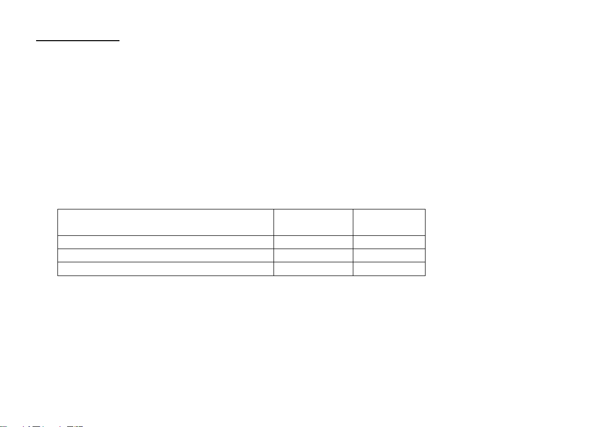
DH05A/B
DH10A/B
FH05A
Specifications
Dimensions [mm]
Total load
Maximum motor current
Maximum operating voltage
Function outputs light: LV, LR
Function outputs AUX1, AUX2
SUSI interface
Connection options
Without connection wires
With ribbon cable for interface per NEM651
With connection wires
13,2 x 6,8 x 1,4
0,5 A
0,5 A
18 V
each 150 mA
each 300 mA
not available
DH05A/B-0
DH05A/B-1
DH05A/B-3
14,3 x 9,2 x 1,8
1,0 A
1,0 A
30 V
each 150 mA
each 300 mA
not available
DH10A/B-0
DH10A/B-1
DH10A/B-3
13,7 x 7,8 x 1,5
0,5 A
--
30 V
each 150 mA
each 300 mA
available
FH05A-0
FH05A-1
FH05A-3
1 Introduction
The locomotive decoder DH05A/B, DH10A/B and FH05A are compatible with the protocols of SelecTRIX
Standard SX1 / SX2 as well as with NMRA-DCC-Standard. They can be controlled by every central control
unit working with one of these data formats.
They can be used for normal direct current motors as well as for coreless motors.
The operation on alternating current supplied layouts with switching impulse is not allowed. The
impulse excitation will destroy the decoder.

5
2 Safety instructions
This product is not suitable for children under 14 years! It might be swallowed by children under 3 years!
An improper use involves a risk of injury due to sharp edges and points.
3 Warranty
The functioning of every decoder is fully tested before delivery. The warranty period is 2 years from the date
of purchase. Should a failure occur during this period please contact the dealer where you purchased the
decoder respectively directly the producer Doehler & Haass.
4 Support and Help
In case you have any problems or questions, please contact us by E-Mail under the address
Normally you will get an answer within a few days.

6
5 Functions
Operation can be controlled either by conventional DC command stations or by digital central units
supporting the formats SelecTRIX 1 and 2 or NMRA-DCC
Automatically switchover from conventional DC to digital operation
In case of digital operation the last programmed system will be activated (no automatically switchover!)
SelecTRIX 1 31 speed steps, 100 addresses
SelecTRIX 2 127 speed steps, 10.000 addresses, 16 additional functions
DCC Short addresses (1-127), long addresses (0001-9999),
with 14, 28, 126 speed steps
Load compensation state of the art, that way an especially smooth regulation behavior
Various regulation variants for an optimal adaptation to the motor
127 internal speed steps
Adjustable motor frequency (low frequency, 16 kHz, 32 kHz)
Block system operation by simple diodes (digital operating system)
Light and function outputs can be dimmed and activated analogically
Shunting gear
Electronic interchange ability of motor, lighting and track connections
All function outputs freely programmable
Thermal protection, insulation
Reset function for DCC and SX2
Decoder can be updated:
The update can be executed on the incorporated decoder when the loco is standing on the track (no
need to open the engine, the SW-Download can be downloaded from the Internet cost free)

7
6 Decoder-Installation
6.1 Preparation
Check if the locomotive is in perfect running order electrically and mechanically, prior to any mounting work.
Defects and dirt must be eliminated first. Pay attention to the instructions of the locomotive producer. Only
locomotives running smoothly in analogue mode, should be equipped with a digital decoder. New
locomotives should be run in at least 30 minutes in each direction of travel.
Before you start, insulate the motor and all its terminals completely against track connections (chassis,
collector slipper, etc.).
Both motor connections must be disconnected from the ground!
Further on, all condensers have to be removed, particularly those associated with the connections of light
and motor.
Fix the decoder with a double sided adhesive tape.
6.2 Check after the insertion
The first test should be executed in the programming mode (e.g. by reading out the address). In case of an
incorrect feedback (confirmation signal) to the central unit ("error"), please check again the correct
assignment of the connections respectively if the motor is really disconnected from the chassis electrically.

8
6.3 Installation
There are three variants to connect the decoder:
1 In case your locomotive is equipped with an interface (NEM 651), you should take the decoder
DH05A/B-1, DH10A/B-1respectively FH05A-1. They have already the appropriate connections for this
plug. Shorten the ribbon cable up to approximately 5 mm and remove the rest of the insulation. The
decoder can be inserted into the interface without any problem now.
2 If the locomotive is not equipped with an interface jack, the decoder must be wired up individually. For
this purpose you should use decoder with flexible wires (DH05A/B-3, DH10A/B-3respectively
FH05A-3).
3 The decoder DH05A/B-0, DH10A/B-0respectively FH05A-0should be used by experienced model
railroaders only as the connection wires must be soldered directly onto the decoder.

9
Connect the decoder wires accordingly to the following diagram:
red wire with the right track wire (G1)
black wire with the left track wire (G2)
orange wire with the motor wire, which was connected to the right track (M1)
gray wire with the motor wire, which was connected to the left track (M2)
white wire with the front light (LV)
yellow wire with the rear light (LR)
In addition for SUSI interface (only if available):
red wire SUSI supply voltage (ZVS)
blue wire SUSI clock (ZCLK)
gray wire SUSI data (ZDAT)
black wire SUSI ground (GND)

10
Function outputs:
The function outputs AUX1 and AUX2 are on the underside of the decoder and must be connected to
the consumers with individual wires (see Illustration, page 2).
Notice:
In case of an incorrect wiring of motor, lighting and track, there is no need to solder off the wires as the
assignment can be interchanged electronically by programming (see adjustment options of the
respective operating system).

11
7 Operating system SelecTRIX 1 (SX1)
7.1 Functions
Speed steps 31
Speed steps (internal) 127
Front light / rear light
Additional functions 2
Additional channel available
(Loco address + 1) with 8 additional functions
7.2 Setup features
All locomotive parameters can be varied by programming freely at any time. Please, take the information
concerning the programming from the instructions of your programming device.
Basic setups
Loco address 01 … 111 (01)
Velocity 1 … 7 (5)
Acceleration / Deceleration 1 … 7 (4)
Impulse width (duration) 1 … 4 (2)
Signal-stopping section 1 / 2 parts (1)
12
Extended setups
Interchange of connections (V) 0 … 7 (4)
Activation of AFB and additional channel (A) 1 … 6 (1)
Motor regulation variant (I) 1 … 4 (3)
AFB ("Automatische Fahr-/Bremssteuerung") = Automatically acceleration / deceleration control
Interchange of connections 0 … 7 (4)
Interchange motor connections 1
Interchange light connections 2
Interchange track connections 4
Activation of AFB and additional channel
Function
With
AFB
Without
AFB
Without additional channel
1
2
With ZK*) without function mapping
3
4
With ZK*) with function mapping
5
6
*) the additional channel ZK ("Zusatzkanal") has always the address: Loco address + 1
Motor regulation variant 1 … 4
User defined by par056 ff. 1
Hard 2
Soft 3
Very soft 4

13
Reading out the extended characteristic values is executed by the entry of the character sequence
00–111
and a subsequently push on the programming key.
Writing of the extended characteristic values is executed by the entry of the character sequence
00=VAI
and a subsequently push on the programming key.
Notice:
Coreless motors should be operated with regulation variant 4 and pulse width 1. Damages due to
incorrect adjustments are excluded from the warranty.
Caution!
Reading out and entering extended characteristic values overwrites the default-values of the decoder.
In case you have varied the extended characteristic values, the default characteristic values of the
decoder must be entered anew.

14
7.3 Operation
Put the locomotive on the programming track and read out the programming parameters of the decoder.
The default value should be 01-542. Program the desired locomotive address and start running the
locomotive keeping the other parameter values. After the first check you can vary the parameters of the
engine freely according to your requirements.
In case your programming device indicates "error", please check again the correct wiring of the locomotive
and pay attention to the wiring instructions of the programming track. Never put such a locomotive into
operation!
7.4 Explication of the signal-stopping section
One-part signal-stopping section:
In front of the signal one track section is controlled by a diode. The decoder must be programmed on
one-part stopping section (-). The locomotive will be braked to a halt.
Two-part signal-stopping section:
In front of the signal there are two track sections. The first one is controlled by a diode and the
locomotive will be braked down to internal speed step 3 in this section. The second one is without
supply and the locomotive will stop just in front of the signal. The decoder must be programmed on
two-part stopping section (=).

15
8 Operating system DCC
8.1 Functions
Short addresses 1 –127
Long addresses 0001 –9999
Speed steps 14, 28, 126
Speed steps (internal) 127
Front light / rear light (can be dimmed)
Additional functions (can be dimmed) 2
Operation with break diodes yes
Operation with break generators yes
Consist mode yes
Full NMRA conform yes
Programming on the main (POM) yes
8.2 Setup features
The characteristics of a locomotive operated in the DCC-operating mode can be varied by programming the
configuration variables (CV) freely at any time. The programming procedure is described in the instructions
of your programming device.
Notice:
In case the speed steps programmed on the decoder differ from those of the control device,
malfunctions may occur. Please pay attention to the respective information concerning your digital
system.
16
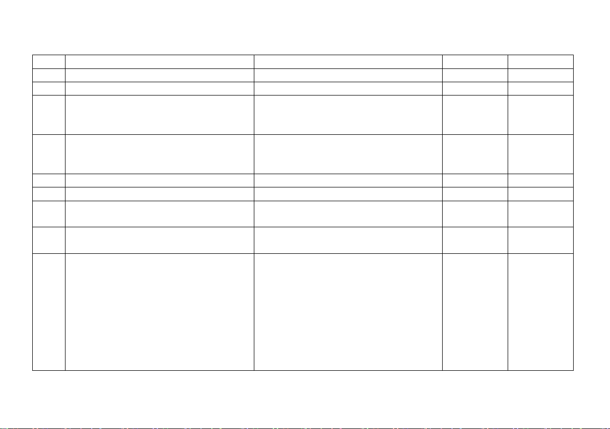
List of supported CV:
CV
Name
Definition
Range
Standard
01
Short address
0 –127
3
02
Starting voltage
Minimum speed
0 –15
0
03
Acceleration time
The value corresponds to the time
in seconds from start to maximum
speed
0 –255
3
04
Deceleration time
The value corresponds to the time
in seconds from maximum speed to
stop
0 –255
3
05
Maximum speed
See supplement 2
0 –127
92
07
Version number
Version number
08
Manufacturer identification
97 = Doehler & Haass
Decoder Reset by "8"
09
Motor frequency
0 = 32 kHz, 1 = 16 kHz,
2 = low frequency
0 –2
0
13
Analog mode F1 –F8
Bit Function Value
0 F1 1
1 F2 2
2 F3 4
3 F4 8
4 F5 16
5 F6 32
6 F7 64
7 F8 128
0 –255
1

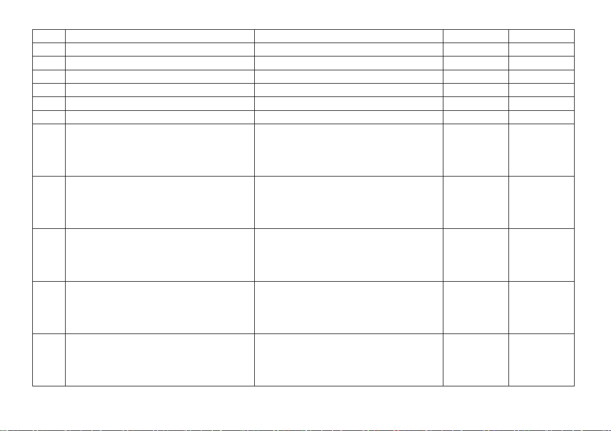
17
14
Analog mode FL, F9 –F12
Bit Function Value
0 FL (f) 1
1 FL (r) 2
2 F9 4
3 F10 8
4 F11 16
5 F12 32
0 –63
3
17
18
Long address
CV17 contains the most significant
byte, CV18 contains the least
significant byte,
Only if activated by CV29
0 –255
192
0
19
Consist address
Several compound locos run under
this address.
0 = deactivated
Value + 128 = inverse direction
0 –127
0
21
Consist mode F1 –F8
Bit Function Value
0 F1 1
1 F2 2
2 F3 4
3 F4 8
4 F5 16
5 F6 32
6 F7 64
7 F8 128
0 –255
0

18
22
Consist mode FL, F9 –F12
0 FL (f) 1
1 FL (r) 2
2 F9 4
3 F10 8
4 F11 16
5 F12 32
0 –63
0
29
Configuration register
Various adjustments
Bit Function
0 Inverse direction
1 14 ↔ 28/126 speed steps
2 Analog operation permitted
3 ---
4 ---
5 Long address by CV17/18
6 ---
7 ---
0 –255
6
33
Function mapping F0(f)
See supplement 1
0 –255
1
34
Function mapping F0(r)
See supplement 1
0 –255
2
35
Function mapping F1(f+r)
See supplement 1
If CV35 is written, CV47 will be set
to the same value
0 –255
4
36
Function mapping F2(f+r)
See supplement 1
If CV36 is written, CV64 will be set
to the same value
0 –255
8
37
Function mapping F3
See supplement 1
0 –255
16
38
Function mapping F4
See supplement 1
0 –255
128
39
Function mapping F5
See supplement 1
0 –255
32
19
40
Function mapping F6
See supplement 1
0 –255
0
41
Function mapping F7
See supplement 1
0 –255
0
42
Function mapping F8
See supplement 1
0 –255
64
43
Function mapping F9
See supplement 1
0 –255
0
44
Function mapping F10
See supplement 1
0 –255
0
45
Function mapping F11
See supplement 1
0 –255
0
46
Function mapping F12
See supplement 1
0 –255
0
47
Function mapping F1(r)
See supplement 1
In case CV47 should have
another value as CV35, you have
to set CV35 first and then CV47
0 –255
4
48
Characteristic diagram
Response curve
0 = linear
7 = logarithmic
See supplement 2
0 –7
5
49
Impulse with
0 = 1 ms
1 = 2 ms
2 = 4 ms
3 = 8 ms
0 –3
1
50
Regulation variant
0 = User defined by CV56 ff.
1 = Hard
2 = Soft
3 = Very Soft
0 –3
2
51
Interchange of connections
Bit Function Value
0 Motor connections 1
1 Light connections 2
2 Track connections 4
0 –7
0
20
52
Dimming light "normal"
0 = off … 31 = full brightness
0 –31
31
53
Dimming light "alternative"
0 = off … 31 = full brightness
0 –31
15
54
Dimming AUX1
0 = off … 31 = full brightness
0 –31
31
55
Dimming AUX2
0 = off … 31 = full brightness
0 –31
31
56
Motor proportional controller
Only if activated by CV50 = 0
0 –7
3
57
Motor integral controller
Only if activated by CV50 = 0
0 –3
3
58
Motor measurement period
Only if activated by CV50 = 0
0 –3
1
59
Motor impulse width
Only if activated by CV50 = 0
0 –7
3
60
Signal-stopping section
1 or 2
0, 1
0
61
Shunting gear speed
0 –127
63
62
Shunting gear deceleration
See CV03
0 –255
1
63
Start delay speed step 1
0 –250
0
64
Function mapping F2(r)
See supplement 1
In case CV64 should have
another value as CV36, you have
to set CV36 first and then CV64
0 –255
8
105
User identifier 1
0 –255
0
106
User identifier 2
0 –255
0
113
Preclusion for LV
Bit 0 = F1 to bit 7 = F8
0 –255
0
114
Preclusion for LR
See CV113
0 –255
0
115
Preclusion for AUX1
See CV113
0 –255
0
116
Preclusion for AUX2
See CV113
0 –255
0
117
Timer for clear AUX1
Each 100 ms, 0 = deactivated
0 –250
0
118
Timer for clear AUX2
Each 100 ms, 0 = deactivated
0 –250
0
119
Timer for clear AUX3
Reserved
120
Timer for clear AUX4
Reserved
This manual suits for next models
2
Table of contents
Other D&H Media Converter manuals


