03 / 2005 IFC 300 9
1.3 Electrical connection of remote sensors (primary heads)
1.3.1 General information on signal cables A and B and field current cable C
Proper functioning is ensured by the KROHNE signal cables A and B with double or
triple foil shielding.
However, when other signal cables are used, please note the following electrical data!
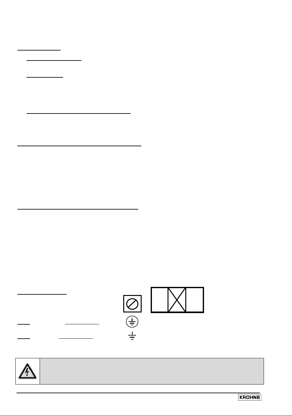
Electrical safety to EN 60811
(low-voltage directives)
or equivalent national standards.
Capacitance of signal wire
wire / wire < 50 pF/m or 15 pF/ft
wire / shield < 150 pF/m or 45 pF/ft
Isolation resisance >100 GΩ × km or >60 GΩ × mile
Voltage rating < 24 V / Current rating < 100 mA
Test voltage
Signal wire / inner shield 500 V
Signal wire / signal wire 1000 V
Signal wire / outer shield 1000 V
Twisting of signal wires
minimum 10× per meter or 3× per feet,
important when screening magnetic fields
•Lay signal cables as a fixed installation, underwater and underground laying possible.
•Connection of shields: - inner (1) via drain wire to normal connecting terminal
- outer (60) via braid to U-clamp terminal
•Insulating material is flame-retardant to EN 50625-2-1,IEC 60322-1.
•The low-halogen, unplasticized signal cables remain flexible at low temperatures.
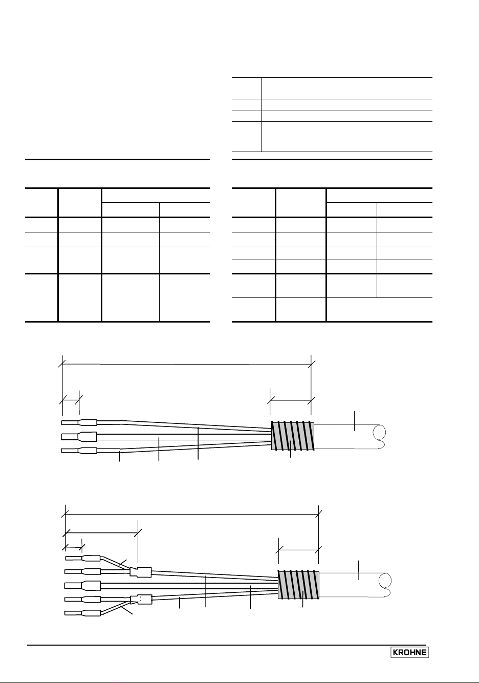
Signal cable A (type DS 300), with double shielding
1Stranded drain wire, inner shield,
1.0 mm² Cu / AWG 17 (not insulated, bare)
10 Inner shield (see stranded drain wire 1)
2Insulated conductor, 0.5 mm² / AWG 20 (marking = 2)
3Insulated conductor, 0.5 mm² / AWG 20 (marking = 3)
6Stranded drain wire, outer shield,
0.5 mm² Cu / AWG 20 (not insulated, bare)
60 Outer shield (see stranded drain wire 6)
Outer sheath, dia. approx. 8 mm / 0.3” (marking = DS 300)
Signal cable B (type BTS 300) with triple shielding (bootstrap line)
1Stranded drain wire, inner shield,
1.0 mm² Cu / AWG 17 (not insulated, bare)
10 Inner shield (see stranded drain wire 1)
2Insulated conductor, 0.5 mm² / AWG 20 (marking = 2)
20 Stranded drain wire for individual shield of conductor 2
3Insulated conductor, 0.5 mm² / AWG 20 (marking = 3)
30 Stranded drain wire for individual shield of conductor 3
6Stranded drain wire, outer shield,
0.5 mm² Cu / AWG 20 (not insulated, bare)
60 Outer shield (see stranded drain wire 6)
Outer sheath, dia. approx. 12 mm / 0.5“ (marking = BTS 300)
In the bootstrap method, the individual shields (20 and 30) are always controlled by the signal converter
to exactly the same voltage that is present at signal wires (2 and 3). Because for that reason there is no
voltage difference between the individual shields (20 and 30) and the signal wires (2 and 3), no current
flows via the line capacitances between 2 / 20 or 3 / 30. The line capacitance is apparently “zero“.
This allows greater cable lengths when the electrical conductivity of the process product is low.
Field current cable C
Cross-section dependent on required length of cable, see Table in Sect. 1.3.3.