5
SPECIFICATIONS
HYDRAULIC SYSTEM ................ Open or Closed Center
MOTOR .........................................................Gear Driven
OPERATING PRESSURE ....................... 1,400-2,000 psi
FLOW RANGE .................................................... 4-7 gpm
OPTIMUM OPERATING PRESSURE ..1,800 psi @ 6 gpm
OUTPUT - FAST ADVANCE MODE ............. 305 in. 3/min
OUTPUT - HIGH PRESSURE MODE ............ 30 in. 3/min
RELIEF VALVE SETTING ................... 4,000 - 10,000 psi
HIGH PRESSURE PORT ............................... 3/8 in. NPT
INLET PORT................................................... 3/8 in. NPT
RETURN PORT .............................................. 3/8 in. NPT
SPECIAL FEATURES
HIGH PRESSURE COUPLER ............................Included
ADJUSTABLE MOUNTING BRACKETS .........Included
UL-BCA - MOUNTING BUCKET ......................Optional
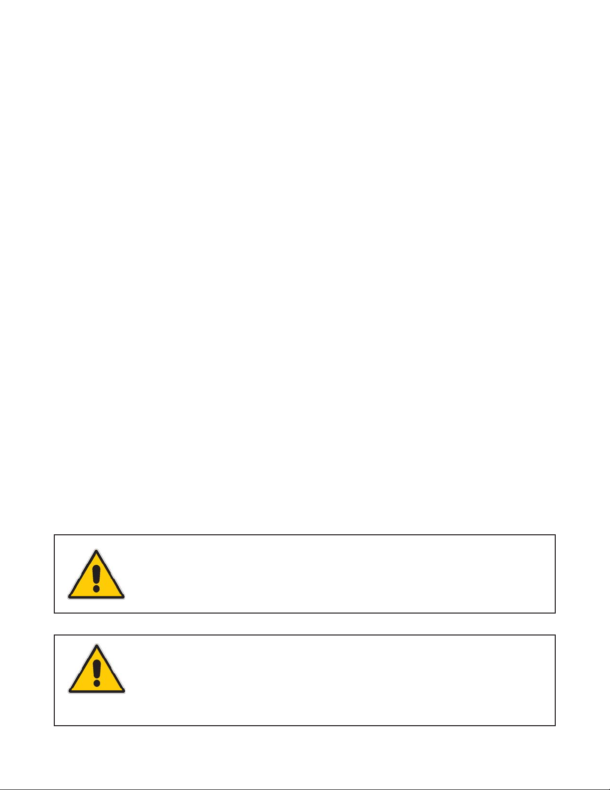
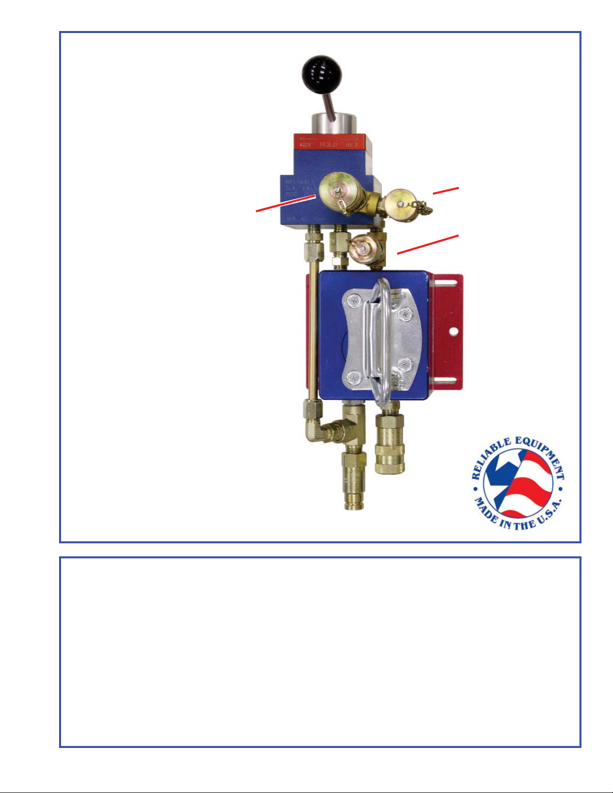
REL-10-I-SA
SINGLE ACTING 10,000
PSI
The REL-10-I-SA provides quick advance
and retract for high pressure (10,000 psi) single
acting spring return tools, without the need for
additional H/P hoses, couplers or an in-line
control valve.
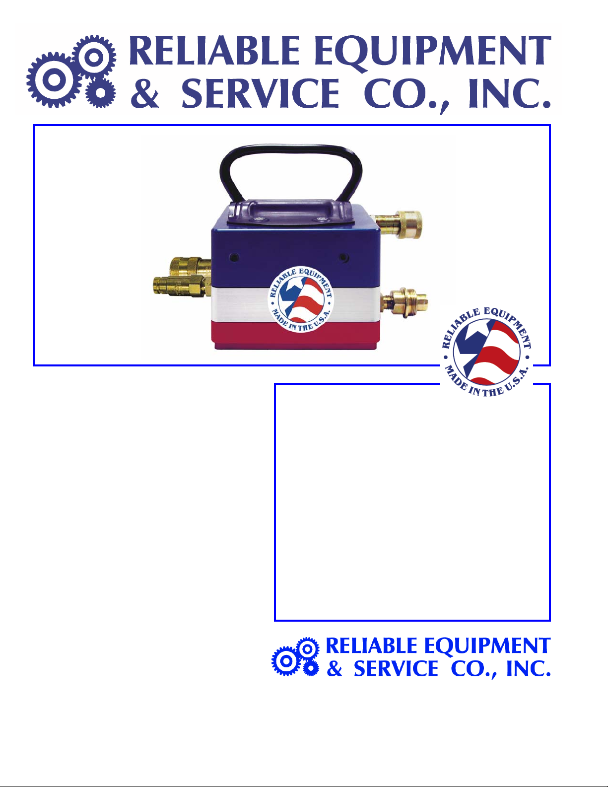
This system combines the power of a high
pressure intensifi er with the simplicity of a fi xed
position three way control valve.
The REL-10-I intensifier will increase line
pressure to a maximum of 10,000 psi and is
fully compatible with all high pressure hydraulic
equipment.
The PVA-00L3 single-acting control valve,
provides 3-way control (Advance, Neutral,
Retract) direct from the high pressure source.
Together this intensifi er/valve package allows
return oil to bypass the intensifi er and return
directly to the tank (return) line, increasing tool
speed and performance.
SPECIFICATIONS - HYD. POWER SOURCE
200 PSI back pressure is the maximum agreed standard for the Hydraulic Tool Manufacturers Association (HTMA).
1. Maximum fluid temperature must not exceed 140OF (60OC) at the maximum expected
ambient temperature. A sufficient oil cooling capacity is needed to limit the fluid temperature.
2. Maximum fl ow must not exceed 8 GPM. Install a fl ow meter in the return line to test the rate of fl ow
in the system before working the tool.
3. Pressure relief valve must not exceed 2,200 PSI. The pressure relief valve must be located in the
supply circuit between the pump and the intensifi er to limit excessive pressure to the tool.
Any hydraulic power source used with this unit must meet the requirements above.
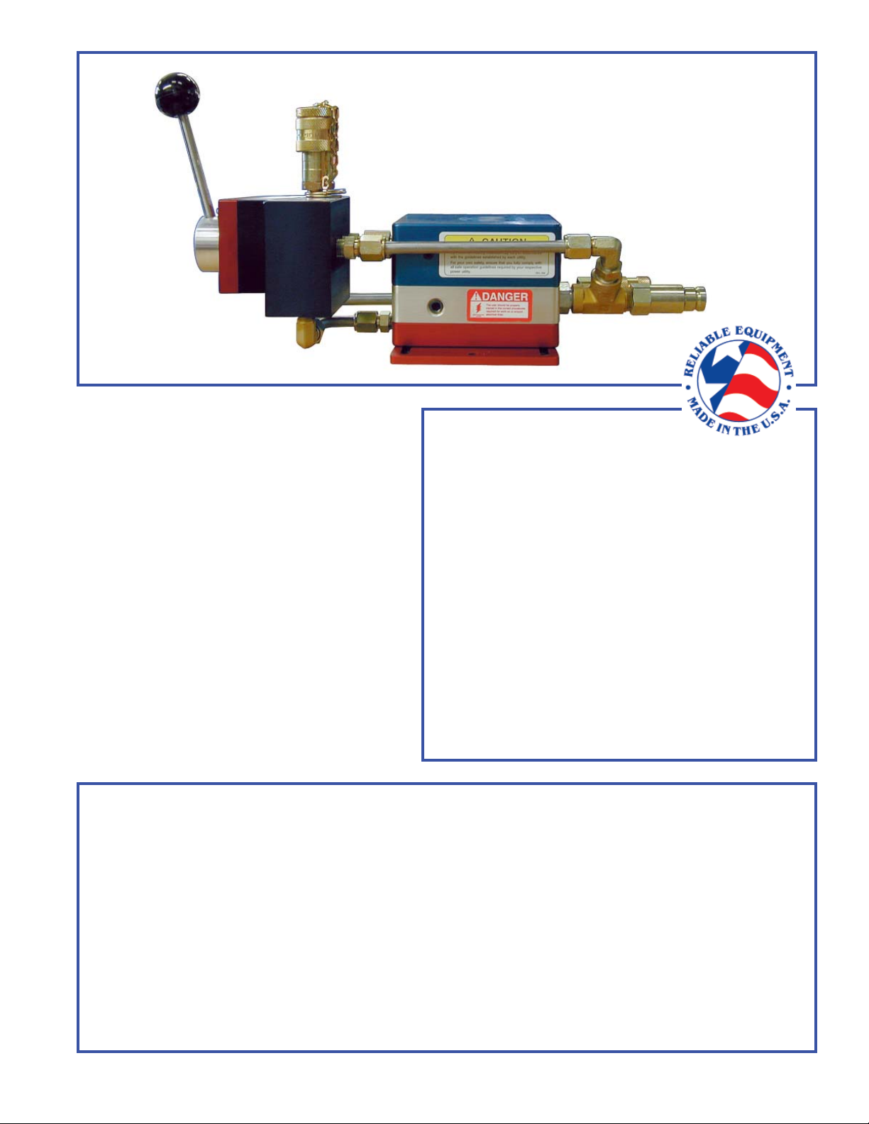
REL-10-I
INTENSIFIER
PVA-00L3
3-WAY VALVE