Reliable Equipment & Service REL-IND-10.5 Manual

1
DISTRIBDISTRIB
DISTRIBDISTRIB
DISTRIBUTED BYUTED BY
UTED BYUTED BY
UTED BY
OPERAOPERA
OPERAOPERA
OPERATT
TT
TORS’ORS’
ORS’ORS’
ORS’ GUIDEGUIDE
GUIDEGUIDE
GUIDE
REL-IND-10.5 Manual 0-1
RELIABLE EQUIPMENT & SERVICE CO., INC.
301 Ivyland Road • Warminster, PA 18974 • USA
Phone: 215-357-3500 • Fax: 215-357-9193
MODEL: __________________________________
MAX. PRESSURE: _________________________
SERIAL NO.: ______________________________
YEAR: ___________________________________
WW
WW
WARNINGARNING
ARNINGARNING
ARNING
All information found in this guide
must be read and understood before
use or testing of this tool.
Failure to read and understand these warnings
and safe handling instructions could result
in severe personal injury and or death.
NOTICENOTICE
NOTICENOTICE
NOTICE
Sizes, weights and tool
specifications listed in
this manual are subject
to change without notice.
Please consult factory for
information and updates.
S/A HYDRAULIC DIELESS INDENT TOOL
REL-IND-10.5
DO NOT OPERATE TOOL
SERIOUS TOOL DAMAGE AND/OR
PERSONAL INJURY MAY RESULT

2
REGISTRATION
UPON RECEIPT OF THIS TOOL, COMPLETE THE REGISTRATION BELOW.
COMPANY _____________________________________________________
ADDRESS ______________________________________________________
_______________________________________________________________
PHONE ___________________ FAX _______________________________
SERIAL NUMBER _______________________________________________
DATE OF PURCHASE____________________________________________
DEALER NAME _________________________________________________
CAUTION
The information in this manual is intended to guide the user in
the use and application of this tool. It is not intended as a
substitute for proper training and experience in safe work
practices for this type of equipment.
Consult your supervisor or safety personnel if you have any
questions regarding the safe operation of this tool.
DISTRIBDISTRIB
DISTRIBDISTRIB
DISTRIBUTED BYUTED BY
UTED BYUTED BY
UTED BY

3
TABLE OF CONTENTS
THIS SYMBOL INDICATES ITEMS OF EXTREME IMPORTANCE.
Safety of user and others may be in jeopardy if these instructions
are not read and understood.
DISTRIBUTOR INFORMATION.......................................................... 2
REGISTRATION.................................................................................... 2
TABLE OF CONTENTS....................................................................... 3
TOOL SPECIFICATIONS
REL-IND-10.5........................................................................... 4
SAFETY INFORMATION AND WARNINGS ...................................5-8
OPERATING INSTRUCTIONS...................................................... 9-10
DAILY MAINTENANCE ...................................................................... 11
MAINTENANCE................................................................................... 11
REL-IND-10.5
PARTS DRAWING #1 - INDENT TOOL ASSEMBLY....... 12
PARTS LIST........................................................................... 13
MAINTENANCE RECORDS ..............................................................14
CONTACT INFORMATION................................................................14
If you have any questions regarding the information
found in this manual please contact RELIABLE EQUIPMENT
at 800-966-3530 or FAX 215-357-9193.
WARNING
Inspection & Testing requirements may vary in accordance with the
working guidelines established by each utility or contractor.
For your own safety, ensure that you fully comply with all safe operation
guidelines required by your employer.

4
301 Ivyland Road • Warminster, PA 18974
Phone: 800-966-3530 • Fax: 215-357-9193
Visit us on the web at www.Reliable-Equip.com
REL-IND-10.5
10.5 TON, HIGH PRESSURE,
HYDRAULIC INDENT TOOL
Operate from any 10,000 psi hydraulic source.
Features a wider opening than comparable
indent tools. ( 2-3/16 in.)
Crimp up to 750 MCM Al. and 800 MCM Cu.
Protective dipped Insulation and Shrink Wrap.
REL-IND-10.5
HYDRAULIC INDENT TOOL
SPECIFICATIONS
System High Pressure Hydraulic
Force 10 .5 Tons
Pressure 10,000 PSI (690 bar)
Couplers 3/8 NPT Female
Capacity 4/0 to 750 Al., 800 Cu.
Jaw Opening 2-3/16 in. (5.56 cm)
Length 12-3/16 in. (30.96 cm)
Weight 9.0 lbs.
Dipped Insulation,
High Pressure Coupler
& Protective Shrink
For more information related to custom tool designs
contact your regional RELIABLE representative.

5
WARNING
BEFORE USING THIS TOOL, READ THE WARNINGS
and the recommended practices described in this manual.
Failure by the operator to read and fully understand these
warnings will leave this person unqualified to use and
operate this tool. Property damage, severe personal injury,
and/or death could result by not following these warnings.
Eye
Protection
These warnings will appear in appropriate locations when they are pertinent to the
particular subject being shown. Read each one carefully and follow them strictly.
WARNING
Always wear eye protection to avoid
injury from flying debris or hydraulic
oil leaks. Failure to do so can result
in serious personal injury.
Hard Hat
WARNING
Alwayswear a hardhat to avoidinjury
from falling debris. Failure to do so
can result in serious personal injury.
Hearing
Protection
WARNING
Always wear hearing protection,
to avoid hearing loss due to long
term exposure to high noise levels.
Foot
Protection
Always wear foot protection.
Failure to do so can result in serious
personal injury.
WARNING
WARNING
Protective
Gloves
Always wear protective gloves
Failure to do so can result in serious
personal injury.
WARNING
Hydraulic oil may cause irritation.
Use care to prevent contact with skin.
In case of accidental contact, wash
affected area immediately
Skin
Irritation

6
WARNING
HYDRAULIC POWER SUPPLY
DO NOT attempt to make any changes to any of the component
parts or accessories when connected to the power source.
DO NOT adjust, inspect, or clean tool while the tool is connected
to the power source. The tool could accidentally start up
and cause serious injury.
DO NOT lock the tool in the On Position. In an emergency,
serious damage or injury could occur during the time
required to stop the tool.
SAFE OPERATION & CARE
USE THIS TOOL FOR ITS INTENDED PURPOSE ONLY
Any other use can result in personal injury or property damage.
INSPECT TOOL BEFORE USE. Replace any worn, damaged or
missing parts. A damaged or improperly assembled tool may
malfunction, injuring operator and/or nearby personnel.
INSPECT HYDRAULIC HOSES AND COUPLINGS before
each use. Repair or replace if any cracking, leakage, wear or
damage is found. Worn or damaged hoses may fail resulting
in personal injury or property damage.
CLEAR WORK AREA of all bystanders and unnecessary
personnel before operating this tool.
KEEP ALL PARTS OF THE BODY AWAY FROM MOVING PARTS.
Failure to observe this warning could result in serious injury.
WARNING
OIL INJECTION INJURY
Hydraulic oil or fluid under the skin is a serious injury. Oil
under pressure can penetrate the skin and may cause
dismemberment or loss of life. Seek medical assistance
immediately if such an injury should occur.
Always wear safety gloves, eye protection and all required
safety equipment when operating or handling this tool.
DO NOT use fingers or hands to attempt to locate a leak.
DO NOT handle hoses or couplers while system is pressurized.
NEVER open or service the system before depressurizing.
WARNING

7
HOSES AND FITTINGS
There exists the potential for shock in using anything other
than certified nonconductive hoses and hydraulic oil with
dielectric properties, when using system components near
energized electrical lines. Failure to recognize these conditions
could cause electrocution.
Hoses and fittings used with this tool must comply with S.A.E. J1273 which
covers recommended practice for selection, installation, and maintenance of hose
and hose assemblies. The correct hoses and fittings are available from your supplier.
WARNING: Failure to comply with these warnings could result in severe bodily injury.
WARNING
UNIT/HOSE CONNECTIONS
ALWAYS DISCONNECT pump/power source and move toggle
switch to OFF before connecting or disconnecting any components.
ALWAYS DEPRESSURIZE hydraulic system, before slowly
disconnecting this unit or any of the systems components.
ALWAYS TIGHTEN couplings completely. Loose or improperly
tightened couplings will not allow fluid to pass through the
hose creating a blockage in the supply or return line.
ALWAYS INSPECT HOSES AND CONNECTORS before
connection to tool. Replace or repair if any leakage is evident.
Leakage is a sign of deterioration in component parts. Worn or
leaking parts must be repaired or replaced, or tool damage or
severe injury could result.
WARNING
WARNING
WARNING
ELECTRICAL SHOCK HAZARD
Always wear and use the necessary clothing, equipment and
safety practices to protect against electrical shock. Failure to
follow these rules can result in serious personal injury or death.
Operation/Safety methods may vary in accordance
with the working guidelines established by each utility
or contractor.
For your own safety, ensure that you fully comply with
all safe operation guidelines required by your employer.

8
GENERAL SAFETYGENERAL SAFETY
GENERAL SAFETY
FAILURE TO HEED THESE WARNINGS COULD RESULT IN
PROPERTY DAMAGE, SERIOUS PERSONAL INJURY OR DEATH.
ELECTRICAL SHOCK HAZARD
Always wear and use the necessary clothing, equipment and
safety practices to protect against electrical shock. Failure to
follow these rules can result in serious personal injury or death.
WARNING
WARNING
COMPRESSION DANGER
This manual hydraulic crimping tool can injure and/or disable.
KEEPALL PARTS OFCTHE BODY AWAY FROM MOVING PARTS.
Failure to observe this warning could result in serious injury
USE ALL APPROPRIATE AND APPLICABLE PERSONAL SAFETY EQUIPMENT
as required by the operating company.
INSPECT TOOL BEFORE USE. Replace any worn, damaged or missing parts.
A damaged orimproperly assembled tool may injure operator and/or nearby personnel.
KEEP ALL PARTS OF THE BODY AWAY from moving parts of the tool.
KEEP HANDS OUT FROM BETWEEN CRIMPING NODES AT TOOL HEAD.
ALL BODY PARTS SHOULD BE OUTSIDE DANGER ZONE PRIOR TO COMPRESSION.
MAKE SURE there is no person in close proximity to you or the tool who could be
injured by any operation being performed, tool malfunction or flying debris.
DO NOT OVEREXTEND your position by overreaching or unbalancing the footing
necessary to maintain physical control of your body and the tool.
ALWAYS MAINTAIN a firm grip on the tool to avoid loss of control during an operation,
causing property damage, serious injury or death.
USE THIS TOOL FOR THE MANUFACTURERS’ INTENDED PURPOSE ONLY.
OBSERVE CLOSELYALL OF THE SAFETY RULES FOR APARTICULAR JOB CLASS
Operation/Safety methods may vary in accordance with the working guidelines
established by each utility or contractor. Ensure that you fully comply with all safe
operation guidelines required by your employer.

9
OPERAOPERA
OPERAOPERA
OPERATIONTION
TIONTION
TION
Read entire manual prior to using this tool. Refer to all SafetyCautions and Warnings.
Observe all safety precautions and procedures required by the operating company.
1. Before crimping, ensure that subject is within the capacity listed for the tool. (see page 4)
Use only with approved in-line sleeves designed for use with a dieless indent tool.
WARNING: Crimping standard “H” Frame (Double Open Groove) connectors may
cause tool damage and void warranty.
2. Ensure that 10,000 psi power source is turned OFF and valve is in OFF position.
3. Connect to a power source. (Refer to page 7 UNIT/HOSE CONNECTION)
A power source with an audible “Pop Off” type relief valve is recommended.
4. Ensure that Indent nib is fully retracted.
6. Place Indent Tool around the connector/conductor assembly.
7. Position subject at a 90O angle to the tool compression head.
KEEP HANDS AND ALL BODY PARTS AWAY FROM COMPRESSION OPERATION
8. Turn power source “ON”.
9. Activate control valve to advance compression nib up to subject. Check tool alignment.
7. Continue to advance until “pop off” is felt or heard and full pressure has been obtained.
8. Return source to the “OFF” position and allow compression nibs to retract completely.
9. Repeat procedure as required by compression sleeve rotating indent 90O at each step.
10. Visually inspect crimp for correctness.
BEFORE USING THIS PRODUCT
READ THE SAFETY WARNINGS
and recommended practices described
in the manual. Failure by the operator
to read and fully understand the
warnings will leave this person
unqualified to use and operate the tool.
Failure to observe all warnings and instructions could result
in property damage, severe personal injury, and/or death.
ELECTROCUTION
HAZARD
The user should be properly
trained in the correct procedures
required for work on or around
electrical lines.
REL-SM
WARNING
NOTE: Keep Label Set clean and legible. Replace decals when necessary.

10
This tool requires well-trained experienced personnel for major repairs, adjustments
or maintenance. Complete disassembly is not recommended. Return the unit to an
authorized dealer for total disassembly and/or repair. It is suggested that tools
requiring repairs be returned to Reliable Equipment for correction unless overall local
conditions are adequate and service training has been provided. Reliable Equipment is
set up to provide quick maintenance and overhaul service. Contact your Reliable
Equipment representative if service is required.
All maintenance or disassembly should take place on a flat, clean work surface covered
with towels or wipers so as to have a clean space for the disassembled parts.
Inspect each part during disassembly for wear, scratches, and cuts. Discard the worn or
damaged parts and replace with new factory authorized parts.
O-rings are sensitive to sharp edges. Inspect closely for cuts or damage. A small cut
will cause a leak. When assembling or disassembling O-rings, use hydraulic fluid as a
lubricant to help disassembly or installation.
NOTICE: When disposing of hydraulic fluid, parts or components observe all federal,
state, and local guidelines.
IF YOU HAVE QUESTIONS REGARDING THE REPAIR AND MAINTENANCE OF THIS TOOL
CONTACT RELIABLE EQUIPMENT OR YOUR RELIABLE EQUIPMENT REPRESENTATIVE.
GENERAL MAINTENANCEGENERAL MAINTENANCE
GENERAL MAINTENANCE
DAILYMAINTENANCE
The life, reliability, and safety of the tool is dependent on proper use and maintenance.
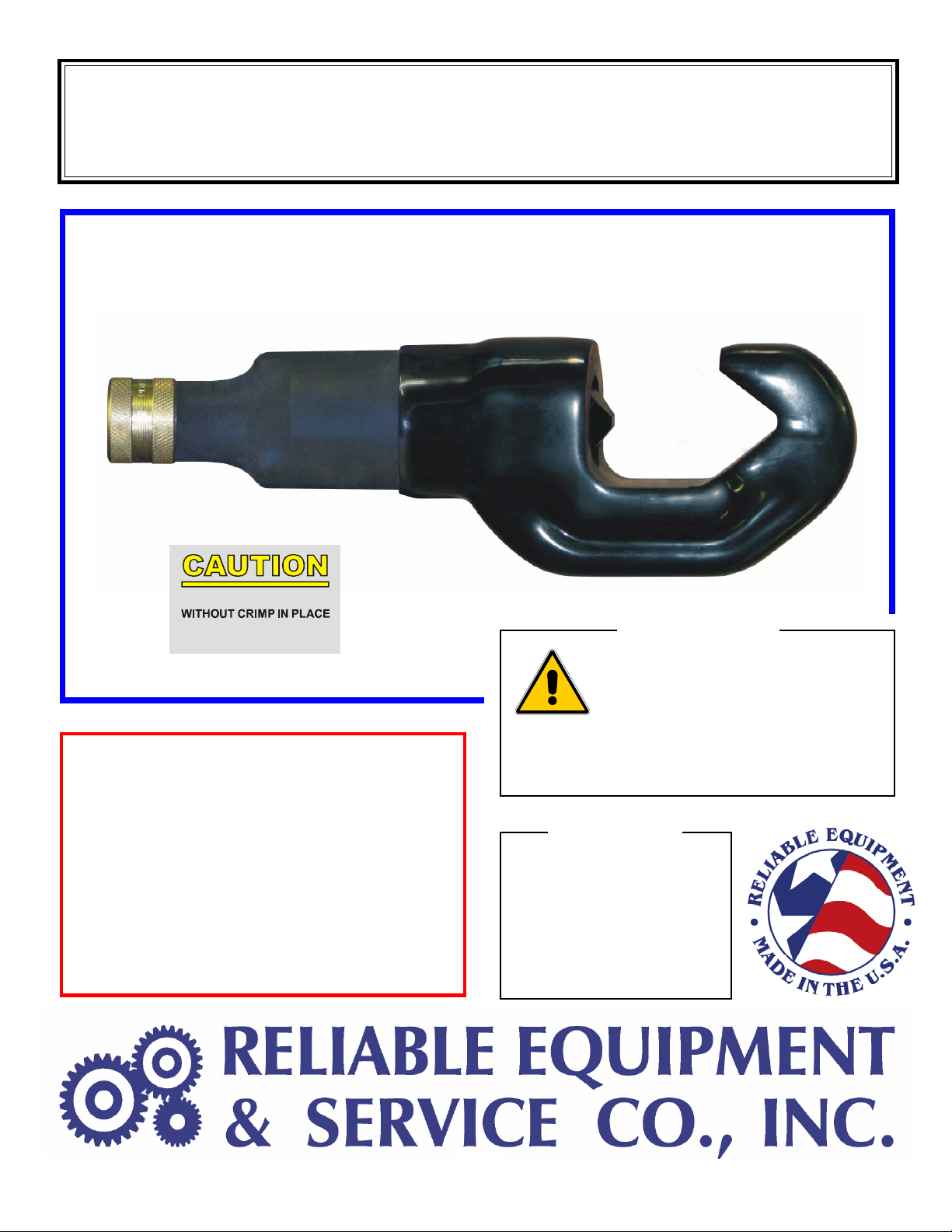
STORE THE TOOL PROPERLY . . . Before storing tools release pressure so that the crimp-
ing nib fully retractS. This protects the operating ram from moisture and condensation.
NOTE: When the tool has been stored for extended period of non-use, the tools should
be activated approximately every 3 weeks to keep o-rings and seals lubricated.
Clean and inspect all surfaces including head, ram, body and coupler.
Particularly avoid joint compounds from building up on the crimping nib.
Inspect for wear and damage. Worn or damaged parts may malfunction during operation,
causing more extensive damage to the tool and/or severe injury to the operator or bystander.
All parts must be replaced with new parts if signs of wear or damage are evident.
Check relief valve pressure setting regularly, using the optional pressure gauge.
(Optional - may be purchased from Reliable Equipment or your local Reliable representative).
Valve should be adjusted or replaced by a trained servie technician if necessary.
DO NOT MAKE ADJUSTMENTS TO THE TOOL . . . There are no adjustments on this
tool which can be made in the field. If a tool becomes inoperative and the instructions in
this booklet do not correct the malfunction have the tool serviced by RELIABLE
EQUIPMENT or an authorized service provider.
Keep Label Set clean and legible. Replace decals when necessary.

11
REL-IND-10.5REL-IND-10.5
REL-IND-10.5
INDENTINDENT
INDENTINDENT
INDENT TT
TT
TOOLOOL
OOLOOL
OOL
ASSEMBLASSEMBL
ASSEMBLASSEMBL
ASSEMBLYY
YY
Y

12
REL-IND-10.5
DIELESS INDENT TOOL PARTS
ITEM PART # QTY DESCRIPTION
1 R50001 1 CRIMP HEAD
2 R50002 1 OUTER CYLINDER
3 R50003 1 RAM
4 R50004 1 COLLAR
5 R50005 1 DIE
6 R50006 1 KEY
7 R50007 1 * WIPER
8 R50008 1 * O’RING
9 R50009 1 * BACKUP RING
10 R28021 2 SET SCREW, M6 X 10
13 R50013 1 SPRING ASSEMBLY
14 R28010 1 BOLT, SPRING SEAL
15 R28011 1 * O-RING, SEAL BOLT
16 R28012 1 * B/U RING, SEAL BOLT
17 R35021 1 SCREW
18 R20287 1 SET SCREW
19 R21022 1 3/16 DIA NYLON BALL
* R50050 SEAL KIT (* ITEMS)
301 Ivyland Road • Warminster, PA 18974
Phone: 800-966-3530 • Fax: 215-357-9193

13
Date Parts or Service Required
Maintenance Records

14
301 Ivyland Road Warminster, PA 18974
Phone: 800-966-3530 Fax: 215-357-9193
Visit us on the web at www.Reliable-Equip.com
If you have any questions regarding the information
found in this manual please contact RELIABLE EQUIPMENT at the
address, phone or fax numbers shown below.
Date Parts or Service Required
Maintenance Records
Table of contents
Other Reliable Equipment & Service Tools manuals
Popular Tools manuals by other brands

Alemlube
Alemlube 630A Owner technical manual

Stanley
Stanley 160173XSTN Instruction manual for owner's use

alkitronic
alkitronic XP Series Operating and maintenance manual

Albert Roller
Albert Roller ROLLER'S King1 1/4 operating instructions

BALADONIA TOOLS
BALADONIA TOOLS MAS-1 owner's manual

BGS GENERAL
BGS GENERAL 5261 instruction manual