Quick Start
Quick Start
Instructions
Instructions
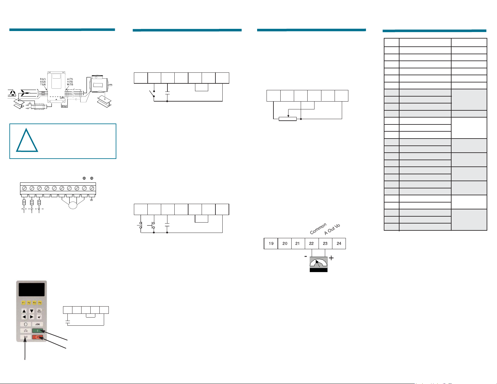
Wiring
Power Up
Parameter Setting
Reliance Electric Drives
SP600 AC Variable Frequency
Inverter - 1/2 to 20 HP
NEMA 4X/12 Washdown
Quick Start Instructions:
A quick reference to some basic
configurations and drive features.
OIM Keypad and Display
The built-in keypad and display allow for
setup, parameter adjustment, monitoring
and diagnostics.
Operator Interface Module (OIM)
NOTE: This material is not intended to provide operational
instructions. Appropriate Reliance Electric Drives
instruction manuals precautions should be studied prior to
installation, operation, or maintenance of equipment.
Quick Start
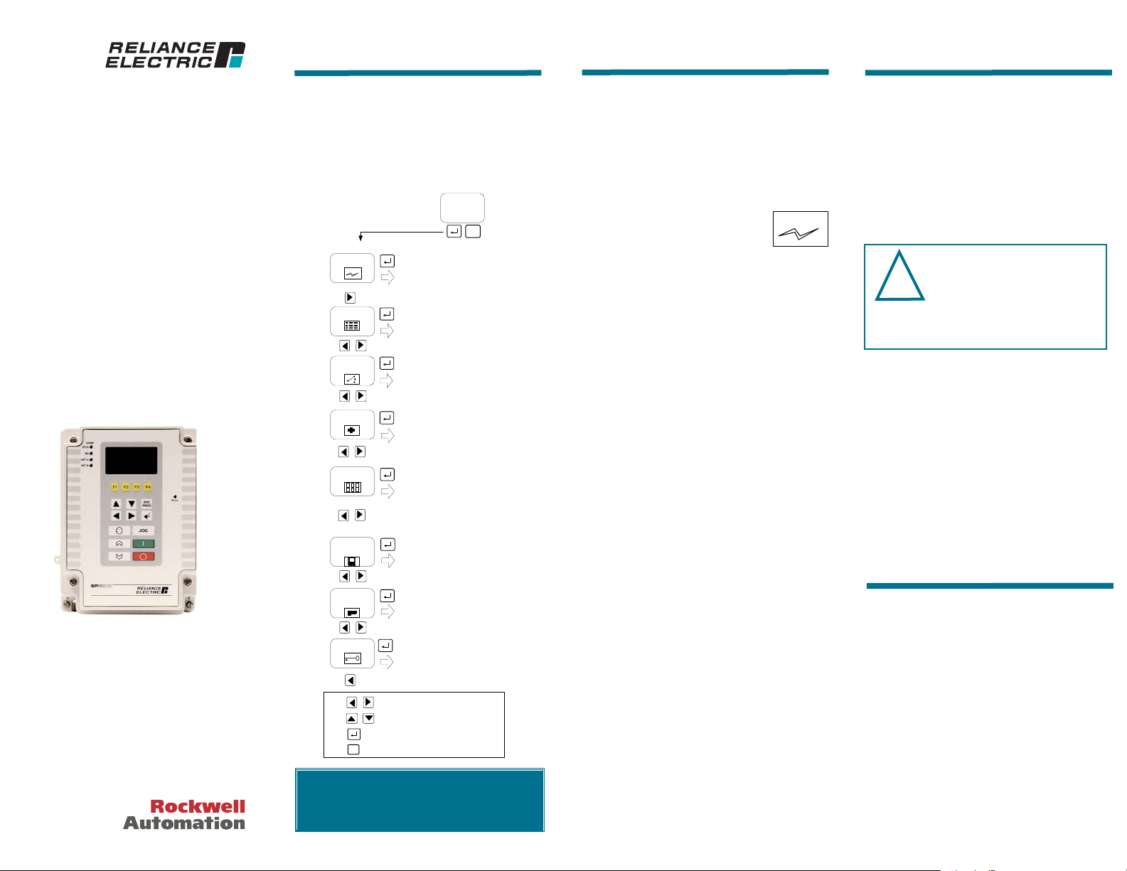
OIM Quick Start Menu
The Quick Start Parameters can be
accessed via the keypad menu icon. Once
into the selection list the following
parameters can be set to configure the
drive to the installed motor.
1) QuickStart
•Stop Mode A (Ramp)
•Motor NP FLA (Drive Dependant)
•Minimum Speed (0.0 Hz)
•Maximum Speed (60.0 Hz)
•Accel. Time 1 (10.0 sec.)
•Decel. Time 1 (10.0 sec.)
•Speed Reference A select (OIM)
•Digital IN2 Select (Start)
(Defaults)
The default configuration is defined as:
Drive Voltage rating = Motor Voltage
Start/Stop control = OIM
Speed Reference = OIM
Control Mode = Sensorless Vector
If the drive default configuration is to be
used for initial startup then the above
parameters are the only settings required.
If the user needs to customize the drive
configuration different than the default
setting, then the user should verify
parameter settings accessible throughout
start-up menu.
2) Input Voltages
•200/240, 400/480, and 575 VAC,
based on model number
3) Motor Nameplate Data
•Motor Power Units
•Motor Power
START-UP
Quick Start
3) Motor Nameplate Data cont’d
•Motor FLA
•Motor Volts
•Motor Hertz
•Motor RPM
4) Motor Tests
•Direction
•AutoTune
5) Speed Limits
•Minimum, Maximum
•Direction Limit
•Stop Mode
6) Reference Setup
•OIM Keypad, Terminal Block,
Network, Other
7) Configure I/O
•Digital Inputs/Outputs
•Analog Outputs
Control Mode
(P53) Torque Perf Mode
Control performance can be selected
from:
•Sensorless Vector (default)
Highest performance mode of control
•SV Economize
Sensorless Vector with energy saving
•Custom V/Hz
Basic open loop control. Multi-motor
application
•Fan/Pump: V/Hz
Provides for a Fan load V/Hz curve
ATTENTION: Rotation of the motor in an
undesired direction can occur during this
procedure Autotune (61) = Rotate Tune
(2). To guard against possible injury
and/or equipment damage, it is recommended that the
motor be disconnected from the load before
proceeding.
!
D-2992