manuals.online logo
Brands
  1. Home
  2. •
  3. Brands
  4. •
  5. Reliance
  6. •
  7. Control Unit
  8. •
  9. Reliance 315.5 User manual

Reliance 315.5 User manual

Design
AS 1357.2
LIC 2532
Field of application
9.0068.09 0449
Maintenance
Operation
Opentheisolatingvalvesaftertheinstallationiscomplete.
Onmodelswithadjustingknob,thepressureisadjustable
between 0,5 and 5 bar (it is factory preset at 4 bar)(see
Fig. A) :
1- Slacken the set screw in the handle.
2- Turn knob counterclockwise (-)
3- Open and close a tap downstream of the pressure
reducer
4- Turn handle clockwise (+) to the desired pressure
5- Tighten set screw
Onsealedmodels,theoutletpressureisindicatedonthe
sealing disc (see Fig. B).
Fig. A Fig. B
Installation
Pressure reducing valve with balanced single-seated
Internals and coaxially arranged strainer. The complete
control unit can be exchanged by removing spring cap
withoutanychangetothedownstreampressuresetting.
Several factory settings are available for downstream
pressure,set oradjustable.
The312valvediffersfromthe315.5valveinthatthelatter
hasacheck-valvemadeofPOM(WRCapproved)inthe
outletport.
Body made of bronze / DZR material; spring cap high
gradeglassreinforcedplastic;diaphragmandsealsmade
ofheatandageproofrubberelasticmaterial,diaphragm
reinforcedbypolyamidefabricinlay;springmadeofspring
steelwire,corrosionprotected;allotherinnerpartsmade
ofsteel1.4305/DZR-material;strainermadeofcorrosion
protected steel, mesh width 0,25 mm.
Pressuregaugeconnection : Rp1/4ISO228/1,
both sides
Inlet pressure: max. 16 bar
Outlet pressure: 0,5 - 5 bar; factory
setting 4 bar
Operatingtemperature: max. 60 °C
Media : water,compressed
air,neutralnon-
adhesiveliquids,
neutralgases
Reductionratio : max. 10:1
Installation position : anyorientation
The pressure reducing valve 312 / 315.5 is used for
reducingpressureinclosedsystemswithmediaasgiven
in the specifications below.
The pressure reducing valve should be fitted free from
stress into the water supply. Installation in the main
supply isrecommendedtoproduceequalpressurevalues
in the whole installation. The valve is protected against
malfunction(causedbydirtparticles)byanincorporated
strainer(meshwidth0,25mm).Incaseofparticlesofless
size,werecommendtheinstallationofaSYRDrufi filter.
Forproperoperation,theinletpressureshallbeatleast1
barhigher, thanthe indicatedoutletpressure.
In cases where irreparable damage has been caused to
thecartridgeasparecartridgecanbepurchasedandfitted
withouttheneedto replacetheentirevalve.
Under normal conditions the pressure reducing valve
shouldnotrequireanyspecialmaintenance.
If the outlet pressure increases to the same level as the
inletpressure,thevalveseatmaybeclogged.Ifso,itwill
be necessary to clean the built in pressure reducer
cartridge.
To do this,
1- Closeisolatingvalvesupstreamanddownstreamof
thepressurereducer
2- Unscrewcap
3- Removethe captogetherwith completecontrolunit
4- Rinsein cleanwater
Donot useany solvents
to clean the strainer as
this may cause damage
to the plastic
components of the valve.
Thecompletecartridgecan
now be replaced into the
body.
Thepressuresettingwillnot
need to be reset due to the
unique design of the SYR
312/315.5valve.
0449-PrintedinGermany 9.0068.09
Pressure reducing
valve
312 / 315.5
Spare parts
Instructions for use
What to do......
ifthedownstreampressurerisesabovethesetpressure
in the case of a pressure reducing valve installed for the
purpose of reducing pressure in a hot water system, the
causeisveryoftenduetopressure crossflowinamixing
valve, due to the fact that the cold water supply has not
beenfittedwith apressurereducer.
Thisoccursespeciallyinthecaseofthermostaticmixing
valves,single-levermixingvalvesornormaltwo-tapmixing
valveswithcloggedanti-splashnozzles.
Such faults can only be eliminated by installing the
pressure reducing valve in the main supply line, thus
reducing the pressure in both, the hot and cold water
supply systems to the same level.
R.W.C. Reliance Water Controls LTD.
Worcester Road, Evesham, WR11 4RA
England
Tel.:0386/47148+9 Fax.: 47028 Tx.:339717
0312.15.900 0,5-5,0 bar
0312.20.901 0,5-2,1 bar
0312.20.902 2,1-6,0 bar
0828.08.000
312
315.5
As an option a PRV 315.5 with
incorporated check-valve is
available.
This to protect up-stream
installations against pollution or /
and back pressure.

This manual suits for next models

1

Other Reliance Control Unit manuals

Reliance Cash Acme EB45 User manual

Reliance

Reliance Cash Acme EB45 User manual

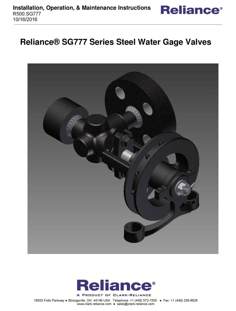
Reliance SG777 Owner's manual

Reliance

Reliance SG777 Owner's manual

Popular Control Unit manuals by other brands

WAGO I/O-SYSTEM 750 manual

WAGO

WAGO I/O-SYSTEM 750 manual

Woodward easYgen-1000 Installation

Woodward

Woodward easYgen-1000 Installation

Busch-Jaeger 6730 manual

Busch-Jaeger

Busch-Jaeger 6730 manual

STRATO Pi CM Series quick reference

STRATO

STRATO Pi CM Series quick reference

Hydac FCU 8000 Series Operating and maintenance instructions

Hydac

Hydac FCU 8000 Series Operating and maintenance instructions

Whelen Engineering Company CenCom Core-S C399S installation guide

Whelen Engineering Company

Whelen Engineering Company CenCom Core-S C399S installation guide

Henco HENCOLOGIC CU-6ZONEB-H quick start guide

Henco

Henco HENCOLOGIC CU-6ZONEB-H quick start guide

Texecom INS656-3 installation instructions

Texecom

Texecom INS656-3 installation instructions

Emerson Fisher D4 instruction manual

Emerson

Emerson Fisher D4 instruction manual

Aliaxis FIP Dual Block VKDIC quick start guide

Aliaxis

Aliaxis FIP Dual Block VKDIC quick start guide

Domestia DMA-004-004 user manual

Domestia

Domestia DMA-004-004 user manual

TLV PN-DR manual

TLV

TLV PN-DR manual

nvent Raychem NGC-30-CR installation instructions

nvent

nvent Raychem NGC-30-CR installation instructions

Advantech ADAM-6217 user manual

Advantech

Advantech ADAM-6217 user manual

APV BV100 Series Installation, operation & maintenance manual

APV

APV BV100 Series Installation, operation & maintenance manual

Nortel 8660 SDM Installing

Nortel

Nortel 8660 SDM Installing

Puls DIMENSION U Series instructions

Puls

Puls DIMENSION U Series instructions

Frapol V370 TECHNICAL-OPERATIONAL DOCUMENTATION

Frapol

Frapol V370 TECHNICAL-OPERATIONAL DOCUMENTATION

manuals.online logo
manuals.online logoBrands
  • About & Mission
  • Contact us
  • Privacy Policy
  • Terms and Conditions

Copyright 2025 Manuals.Online. All Rights Reserved.