•
•
Figure
1.1
2.1
2.2
3.1
3.2
3.3
3.4
3.5
3.6
4.1
5.1
5.2
5.3
5.4
5.5
5.6
5.7
5.8
5.9
5.10
5.11
5.12
Table
2.A
2.B
2.C
2.0
3.A
3.B
3.C
5.A
LIST OF FIGURES
Title Page
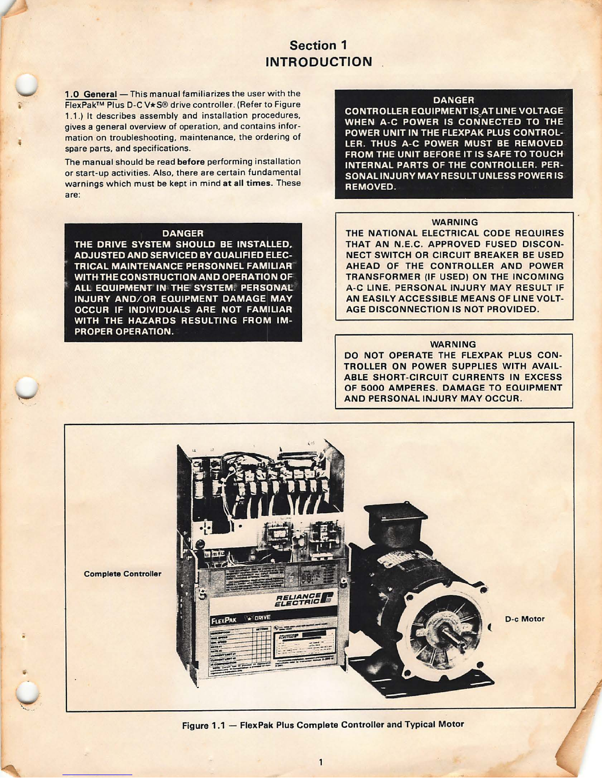
FlexPak Plus Complete Controller
and Typical Motor. . . . . . . . . . . . . . . . . . . . . . 1
Basic Controller and Auxiliary Panel ...... . 3
FlexPak Plus Complete Controller
with Modification Kits ... .. . ... .. .. ... .. 4
Enclosure Mounting Minimum
Distances .................. . ... . . ... .. 9
Mounting and Wiring Orientations . . ..... 10
Mounting Dimens ions ................... 11
System Connection Diagram . ..... . ...... 12
50-Hz Resistor Removal ................. 13
HP/ Current Scaling Pins ................ 14
Regulator Module Pots ..... . .. . .. . ...... 16
Pin Alignment .... ........ .. . ........... 19
Auxiliary Panel Mounting ................ 19
Dynamic Braking Kit .... . ...... .. ... . .. . 20
Dynamic Braking Kit Installed ............ 21
Dynamic Braking Connections ........... 21
Reversing Contactor Connections ........ 21
Automatic Reversing Kit ............. .... 21
Tachometer Feedback Kit .. ... .. .. .... ... 22
Jumpers J1, J2 ......... .. ... ... .. .... . . 23
Feedback Connection on
Regulator Module . .. .......... ........ 23
Voltage/ Tachometer Follower ............ 24
Jumper J1 ............................. 24
Figure
5.13
5.14
5.15
5.16
5.17
5.18
5.19
5.20
5.21
5.22
5.23
5.24
5.25
5.26
5.27
6.1
6.2
6.3
6.4
6.5
6.6
6.7
LIST OF TABLES
Title Page
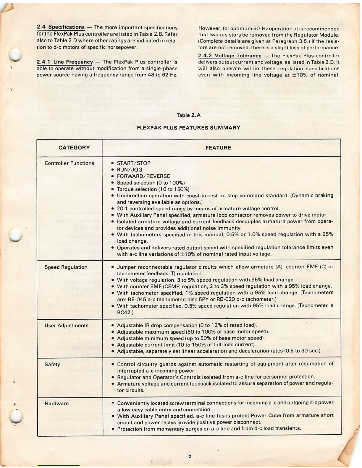
FlexPak Plus Features Summary . . ........ 5
Specifications ... ....... . .. ........ . . . .. . 6
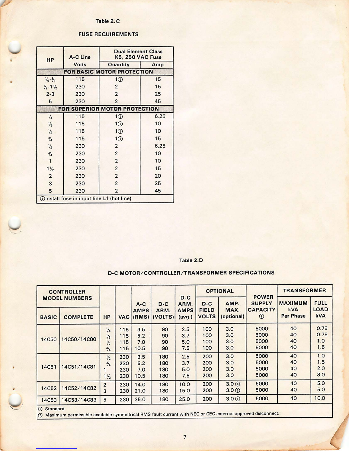
Fuse Requirements ...... .. . .. ........... 7
0-C Motor / Controller / Transformer
Specifications . . . . . . . . . . . . . . . . . . . . . . . . . 7
Typical Wire, Fuse Sizes ................. 10
Reliance Electric Isolation Transformers .. 13
Horsepower Calibration .... .... ......... 14
Modification Kit Quick Reference List ..... 20
iii
Table
5.B
5.C
5.0
6.A
6.8
6.C
7.A
Title Page
Instrument Interface Kit ................. 25
Jumper Jl , mA Pins . .... ............... 25
Field Supp ly Kit ......................... 26
Connecting Field Supply ............... . . 26
Torque Taper Kit ... .. ... . ... ............ 26
Torque Curves .... . .... .. ............... 26
Auxiliary M Contactor Kit . ... ... ....... . . 27
External Wiring, Auxiliary M .. . .......... 27
Test Meter Adapter .......... . . . . .. ...... 28
Dancer Follower Module ................ 28
Jumpers J1, J2 and Resistor (R6) .... ... . 29
Master Isolated Reference
Receiver Kit ............... . . . ........ 29
Jumpers J1 and J2 on Switc h
Receiver Module ........ .. ............ 30
Jumper J1 on Reference
Receiver Module ... .. .. . .............. 30
Connecting User-supplied
FM and RM Contactors .... . ... .. .. .. . . 31
Unidirectional Control Circuit ............ 34
Bidirectiona l Control Circuit ..... .. ....... 35
Relay Control Sequencing . .. ........ . ... 35
Regulation Module Screen ............... 36
Controller Schematic .................... 43
Modification Kits Schemati cs ......... 44, 45
Controller Technical Data .. . ... .. ........ 46
Title Page
Tachometer Voltage Scaling ..... .. ....... 22
Wire Specifications ..................... 23
Test Adapter Terminals, Readings ...... .. 28
Color Coding System ........... ... ...... 34
Troubleshooting Suggestions for
the Basic Controller . ..... ............. 37
Troubleshooting Suggestions for
the Complete Controlle r ............... 40
Replacemen t Modules ..... .. ....... .. ... 47