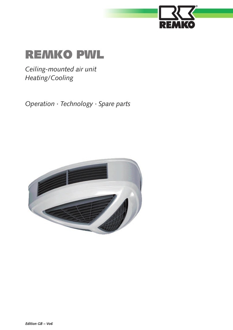
REMKO KWK ZW Series User manual

Operating and
installation instructions
Read the instructions prior to performing any task!
REMKO KWK ZW series
KWK 125 ZW, KWK 165 ZW, KWK 205 ZW, KWK 255 ZW, KWK 305 ZW,
Cold water wall and ceiling units
0256-2020-02 Edition 1, en_GB
KWK 355 ZW, KWK 455 ZW, KWK 535 ZW, KWK 595 ZW, KWK 725 ZW

Translation of the original
Read these operating instructions carefully before commis-
sioning / using this device!
These instructions are an integral part of the system and must
always be kept near or on the device.
Subject to modifications; No liability accepted for errors or mis-
prints!

Table of contents
1 Safety and usage instructions............................................................................................................. 4
1.1 General safety notes....................................................................................................................... 4
1.2 Identification of notes...................................................................................................................... 4
1.3 Personnel qualifications.................................................................................................................. 4
1.4 Dangers of failure to observe the safety notes................................................................................ 4
1.5 Safety-conscious working............................................................................................................... 4
1.6 Safety notes for the operator........................................................................................................... 5
1.7 Safety notes for installation, maintenance and inspection.............................................................. 5
1.8 Unauthorised modification and changes......................................................................................... 5
1.9 Intended use................................................................................................................................... 5
1.10 Warranty........................................................................................................................................ 5
1.11 Transport and packaging............................................................................................................... 6
1.12 Environmental protection and recycling........................................................................................ 6
2 Technical data........................................................................................................................................ 7
2.1 Unit data KWK 125-255 -ZW........................................................................................................... 7
2.2 Unit data KWK 305-455 -ZW........................................................................................................... 9
2.3 Unit data KWK 535-725 -ZW......................................................................................................... 11
2.4 Unit dimensions............................................................................................................................. 13
3 Design and function............................................................................................................................ 14
3.1 Unit description............................................................................................................................. 14
3.2 System layout................................................................................................................................ 15
4 Operation............................................................................................................................................. 17
5Installation instructions for qualified personnel.............................................................................. 18
6 Installation........................................................................................................................................... 22
6.1 Unit installation.............................................................................................................................. 22
6.2 Condensate drainage connection................................................................................................. 25
6.3 Leak testing................................................................................................................................... 25
7 Electrical wiring................................................................................................................................... 26
8 Before commissioning....................................................................................................................... 27
9 Commissioning................................................................................................................................... 27
10 Shutdown............................................................................................................................................. 28
11 Troubleshooting and customer service............................................................................................ 29
12 Care and maintenance........................................................................................................................ 31
13 General view of unit and spare parts................................................................................................ 34
13.1 Exploded view of the unit KWK 125 - KWK 725 ZW................................................................... 34
13.2 Spare parts list KWK 125 - KWK 725 ZW................................................................................... 35
14 Index..................................................................................................................................................... 36
3

1 Safety and
usage instructions
1.1 General safety notes
Carefully read the operating manual before com-
missioning the units for the first time. It contains
useful tips and notes such as hazard warnings to
prevent personal injury and material damage.
Failure to follow the directions in this manual not
only presents a danger to people, the environment
and the system itself, but will void any claims for
liability.
Keep this operating manual and the refrigerant
data sheet near to the units.
1.2 Identification of notes
This section provides an overview of all important
safety aspects for proper protection of people and
safe and fault-free operation.The instructions and
safety notes contained within this manual must be
observed in order to prevent accidents, personal
injury and material damage.
Notes attached directly to the units must be
observed in their entirety and be kept in a fully
legible condition.
Safety notes in this manual are indicated by sym-
bols. Safety notes are introduced with signal words
which help to highlight the magnitude of the danger
in question.
DANGER!
Contact with live parts poses an immediate
danger of death due to electric shock. Damage
to the insulation or individual components may
pose a danger of death.
DANGER!
This combination of symbol and signal word
warns of a situation in which there is immediate
danger, which if not avoided may be fatal or
cause serious injury.
WARNING!
This combination of symbol and signal word
warns of a potentially hazardous situation,
which if not avoided may be fatal or cause
serious injury.
CAUTION!
This combination of symbol and signal word
warns of a potentially hazardous situation,
which if not avoided may cause injury or mate-
rial and environmental damage.
NOTICE!
This combination of symbol and signal word
warns of a potentially hazardous situation,
which if not avoided may cause material and
environmental damage.
This symbol highlights useful tips and recom-
mendations as well as information for efficient
and fault-free operation.
1.3 Personnel qualifications
Personnel responsible for commissioning, opera-
tion, maintenance, inspection and installation must
be able to demonstrate that they hold a qualifica-
tion which proves their ability to undertake the
work.
1.4 Dangers of failure to observe
the safety notes
Failure to observe the safety notes may pose a risk
to people, the environment and the units. Failure to
observe the safety notes may void any claims for
damages.
In particular, failure to observe the safety notes
may pose the following risks:
nThe failure of important unit functions.
nThe failure of prescribed methods of mainte-
nance and repair.
nDanger to people on account of electrical and
mechanical effects.
1.5 Safety-conscious working
The safety notes contained in this manual, the
existing national regulations concerning accident
prevention as well as any internal company
working, operating and safety regulations must be
observed.
REMKO KWK ZW series
4

1.6 Safety notes for the operator
The operational safety of the units and compo-
nents is only assured providing they are used as
intended and in a fully assembled state.
nThe units and components may only be set up,
installed and maintained by qualified per-
sonnel.
nProtective covers (grille) over moving parts
must not be removed from units that are in
operation.
nDo not operate units or components with
obvious defects or signs of damage.
nContact with certain unit parts or components
may lead to burns or injury.
nThe units and components must not be
exposed to any mechanical load, extreme
levels of humidity or extreme temperature.
nSpaces in which refrigerant can leak sufficient
to load and vent. Otherwise there is danger of
suffocation.
nAll housing parts and device openings, e.g. air
inlets and outlets, must be free from foreign
objects, fluids or gases.
nThe units must be inspected by a service tech-
nician at least once annually. Visual inspec-
tions and cleaning may be performed by the
operator when the units are disconnected from
the mains.
1.7 Safety notes for installation,
maintenance and inspection
nAppropriate hazard prevention measures must
be taken to prevent risks to people when per-
forming installation, repair, maintenance or
cleaning work on the units.
nThe setup, connection and operation of the
units and its components must be undertaken
in accordance with the usage and operating
conditions stipulated in this manual and comply
with all applicable regional regulations.
nLocal regulations and laws such as Water
Ecology Act must be observed.
nThe power supply should be adapted to the
requirements of the units.
nUnits may only be mounted at the points pro-
vided for this purpose at the factory. The units
may only be secured or mounted on stable
structures, walls or floors.
nMobile units must be set up securely on suit-
able surfaces and in an upright position. Sta-
tionary units must be permanently installed for
operation.
nThe units and components should not be oper-
ated in areas where there is a heightened risk
of damage. Observe the minimum clearances.
nThe units and components must be kept at an
adequate distance from flammable, explosive,
combustible, abrasive and dirty areas or
atmospheres.
nSafety devices must not be altered or
bypassed.
1.8 Unauthorised modification
and changes
Modifications or changes to units and components
are not permitted and may cause malfunctions.
Safety devices may not be modified or bypassed.
Original replacement parts and accessories
authorised by the manufactured ensure safety. The
use of other parts may invalidate liability for
resulting consequences.
1.9 Intended use
Depending on the model and the equipment, the
units are only intended to be used as a cold water
drain to cool or warm the operating medium water
or a water-glycol mixture within a closed medium
cycle.
Any different or additional use is a non-intended
use. The manufacturer/supplier assumes no lia-
bility for damages arising from non-intended use.
The user bears the sole risk in such cases.
Intended use also includes working in accordance
with the operating and installation instructions and
complying with the maintenance requirements.
The threshold values specified in the technical
data must not be exceeded.
1.10 Warranty
For warranty claims to be considered, it is essential
that the ordering party or its representative com-
plete and return the "certificate of warranty" to
REMKO GmbH & Co. KG at the time when the
units are purchased and commissioned.
The warranty conditions are detailed in the "Gen-
eral business and delivery conditions". Further-
more, only the parties to a contract can conclude
special agreements beyond these conditions. In
this case, contact your contractual partner in the
first instance.
5

1.11 Transport and packaging
The devices are supplied in a sturdy shipping con-
tainer. Please check the equipment immediately
upon delivery and note any damage or missing
parts on the delivery and inform the shipper and
your contractual partner. For later complaints can
not be guaranteed.
WARNING!
Plastic films and bags etc. are dangerous
toys for children!
Why:
- Leave packaging material are not around.
- Packaging material may not be accessible to
children!
1.12 Environmental protection
and recycling
Disposal of packaging
All products are packed for transport in environ-
mentally friendly materials. Make a valuable contri-
bution to reducing waste and sustaining raw mate-
rials. Only dispose of packaging at approved
collection points.
Disposal of equipment and components
Only recyclable materials are used in the manufac-
ture of the devices and components. Help protect
the environment by ensuring that the devices or
components (for example batteries) are not dis-
posed in household waste, but only in accordance
with local regulations and in an environmentally
safe manner, e.g. using certified firms and recy-
cling specialists or at collection points.
REMKO KWK ZW series
6

2 Technical data
2.1 Unit data KWK 125-255 -ZW
Series KWK 125
ZW
KWK 165
ZW
KWK 205
ZW
KWK 255
ZW
Operating mode Chilled water units for wall and ceiling mounting, 2-con-
ductor version
Nominal cooling output 1) kW 1.20 1.63 2.09 2.51
Nominal heat capacity 2) kW 1.49 2.02 2.42 2.87
Application area (room volume),
approx. 3) m3) 40 50 60 80
Operating range - indoor unit °C +15 to +35
Air flow volume per stage m3/h 120/200/260 140/220/290 190/290/370 210/320/410
Sound pressure level per stage 3) dB (A) 17/25/32 23/31/39
Sound power level per stage dB (A) 25/33/40 31/39/47
Power supply V/Ph/
Hz 230/1~ /50
Enclosure class IP X0
Electrical rated power consumption 1) W 35 39 47 51
Electrical rated current consumption 1) A 0.15 0.17 0.20 0.22
Operating medium max. 35% ethylene glycol, max. 35% propylene glycol
Operating limits, medium - cooling °C +4 to +18
Operating limits, medium - heating °C +35 to +80
Operating pressure, medium, max. kPa 1500
Nominal flow rate, medium - cooling 1) m3/h 0.21 0.28 0.36 0.43
Nominal flow rate, medium - heating 2) m3/h 0.26 0.35 0.42 0.49
Rated press. drop, internal - cooling 1) kPa 10.5 13.3 15.3 17.3
Rated press. drop, internal - heating 2) kPa 13.0 16.5 17.7 19.7
Medium connection, inlet Inches 1/2
Medium connection, outlet Inches 1/2
Medium volume l 0.7 1.0
Condensate drainage connection mm 20
7

Series KWK 125
ZW
KWK 165
ZW
KWK 205
ZW
KWK 255
ZW
Dimensions
Height mm 450
Width mm 545 745
Depth mm 215
Weight kg 11.1 11.6 13.9 14.7
Operating weight, approx. kg 11.8 12.3 14.9 15.7
Serial number 1962... 1963... 1964... 1965...
EDP no. 1664300 1664310 1664320 1664330
1) Air inlet temperature TK 27 °C / FK 19 °C, medium inlet 7 ℃, medium outlet 12 °C, 0% glycol concentra-
tion, max. air flow volume
2) Air inlet temperature TK 20 °C, medium inlet 45 °C, medium outlet 40 °C, 0% glycol concentration, max. air
flow volume
3) Distance of 1.0 m in a 100 m3) space with a reverberation time of 0.3 s
REMKO KWK ZW series
8

2.2 Unit data KWK 305-455 -ZW
Series KWK 305
ZW
KWK 355
ZW
KWK 455
ZW
Operating mode Chilled water units for wall and ceiling
mounting, 2-conductor version
Nominal cooling output 1) kW 3.08 3.51 4.54
Nominal heat capacity 2) kW 3.47 4.03 4.95
Application area (room volume), approx. 3) m3) 100 120 150
Operating range - indoor unit °C +15 to +35
Air flow volume per stage m3/h 280/390/490 310/420/530 400/570/730
Sound pressure level per stage 3) dB (A) 21/27/33 26/34/42
Sound power level per stage dB (A) 29/35/41 34/42/50
Power supply V/Ph/Hz 230/1~ /50
Enclosure class IP X0
Electrical rated power consumption 1) W 59 71 97
Electrical rated current consumption 1) A 0.26 0.31 0.42
Operating medium max. 35% ethylene glycol, max. 35% pro-
pylene glycol
Operating limits, medium - cooling °C +4 to +18
Operating limits, medium - heating °C +35 to +80
Operating pressure, medium, max. kPa 1500
Nominal flow rate, medium - cooling 1) m3/h 0.53 0.60 0.78
Nominal flow rate, medium - heating 2) m3/h 0.60 0.69 0.87
Rated pressure drop, internal - cooling 1) kPa 18.6 19.9 20.2
Rated pressure drop, internal - heating 2) kPa 20.9 22.9 22.5
Medium connection, inlet Inches 1/2
Medium connection, outlet Inches 1/2
Medium volume l 1.4 1.7
Condensate drainage connection mm 20
9

Series KWK 305
ZW
KWK 355
ZW
KWK 455
ZW
Dimensions
Height mm 450
Width mm 945 1145
Depth mm 215
Weight kg 19.9 20.9 23.3
Operating weight, approx. kg 21.3 22.3 25
Serial number 1966... 1967... 1968...
EDP no. 1664340 1664350 1664360
1) Air inlet temperature TK 27 °C / FK 19 °C, medium inlet 7 ℃, medium outlet 12 °C, 0% glycol concentra-
tion, max. air flow volume
2) Air inlet temperature TK 20 °C, medium inlet 45 °C, medium outlet 40 °C, 0% glycol concentration, max. air
flow volume
3) Distance of 1.0 m in a 100 m3) space with a reverberation time of 0.3 s
REMKO KWK ZW series
10

2.3 Unit data KWK 535-725 -ZW
Series KWK 535
ZW
KWK 595
ZW
KWK 725
ZW
Operating mode Chilled water units for wall and ceiling
mounting, 2-conductor version
Nominal cooling output 1) kW 5.35 5.92 7.24
Nominal heat capacity 2) kW 5.77 6.27 7.65
Application area (room volume), approx. 3) m3) 180 190 230
Operating range - indoor unit °C +15 to +35
Air flow volume per stage m3/h 430/610/780 420/630/870 450/670/920
Sound pressure level per stage 3) dB (A) 26/34/42 24/33/43 24/33/43
Sound power level per stage dB (A) 34/42/50 32/41/51 32/41/51
Power supply V/Ph/Hz 230/1~ /50
Enclosure class IP X0
Electrical rated power consumption 1) W 107 120 139
Electrical rated current consumption 1) A 0.47 0.52 0.60
Operating medium max. 35% ethylene glycol, max. 35% pro-
pylene glycol
Operating limits, medium - cooling °C +4 to +18
Operating limits, medium - heating °C +35 to +80
Operating pressure, medium, max. kPa 1500
Nominal flow rate, medium - cooling 1) m3/h 0.92 1.02 1.24
Nominal flow rate, medium - heating 2) m3/h 0.99 1.08 1.31
Rated pressure drop, internal - cooling 1) kPa 22.6 23.4
Rated pressure drop, internal - heating 2) kPa 24.3 24.0 24.8
Medium connection, inlet Inches 1/2
Medium connection, outlet Inches 1/2
Medium volume l 1.7 2.0
Condensate drainage connection mm 20
11

Series KWK 535
ZW
KWK 595
ZW
KWK 725
ZW
Dimensions
Height mm 450
Width mm 1145 1345
Depth mm 215
Weight kg 24.8 27.2 28.7
Operating weight, approx. kg 26.5 29.2 30.7
Serial number 1969... 1970... 1971...
EDP no. 1664370 1664380 1664390
1) Air inlet temperature TK 27 °C / FK 19 °C, medium inlet 7 ℃, medium outlet 12 °C, 0% glycol concentra-
tion, max. air flow volume
2) Air inlet temperature TK 20 °C, medium inlet 45 °C, medium outlet 40 °C, 0% glycol concentration, max. air
flow volume
3) Distance of 1.0 m in a 100 m3) space with a reverberation time of 0.3 s
REMKO KWK ZW series
12

2.4 Unit dimensions
Dimensions KWK 125-KWK 725
B
230
120
450
260 135
40
40
215
A
A
B
Fig. 1: Unit dimensions (all measurements in mm)
Dimen-
sion
KWK
125
ZW
KWK
165
ZW
KWK
205
ZW
KWK
255
ZW
KWK
305
ZW
KWK
355
ZW
KWK
455
ZW
KWK
535
ZW
KWK
595
ZW
KWK
725
ZW
A 545 545 745 745 945 945 1145 1145 1345 1345
B 425 425 625 625 825 825 1025 1025 1225 1225
We reserve the right to modify the dimensions and design as part of the ongoing technical development
process.
13

3 Design and function
3.1 Unit description
In cooling mode the unit (chilled water outlet)
extracts the heat from the interior room to be
cooled into the fin register and passes it on to the
cold operating medium - water or a mix of water
and glycol - within a closed medium cycle. As a
result of the heat exchange the medium heats up
and the emergent air cools the room down.
In heating mode, a warm operating medium warms
the room to be heated. The medium cools down as
a result of the heat exchange.
A valve assembly, which routes the operating
medium through the register (energy is given up)
or past the resister (energy is not given up), is
used to control the cooling or heating capacity.
The unit is designed for use indoors in the lower
wall area (vertical installation) and for ceiling instal-
lation (horizontal installation). Operation is either
individually or in groups using room temperature
regulation or via the building management system.
The unit consists of a fin heat exchanger, circula-
tion fan and two condensate trays for horizontal
and vertical installation.
The available accessories include room tempera-
ture controllers for installation in the unit or on the
wall, heating coil for connection to a 4-wire system,
valve assembly cooling, fan modules, air inlet
plinth, duct parts, grille and condensate pumps.
2
1
4
3
5
Fig. 2: Diagram of a 2-conductor system medium
cycle
1: Cooling register
2: Recirculating fan
3: Medium inlet connection
4: Medium outlet connection
5: Valve assembly (accessory)
2
1
4
3
5
8
7
6
910
Fig. 3: Diagram of a 4-conductor system medium
cycle (with heating register)
1: Cooling register
2: Recirculating fan
3: Cooling register connection medium inlet
4: Cooling register connection medium outlet
5: Valve assembly (accessory)
6: Heating register (accessory)
7: Heating register connection medium outlet
8: Heating register connection medium inlet
9: 3-way valve assembly heating (accessory)
10: 2-way valve assembly heating (accessory)
REMKO KWK ZW series
14

3.2 System layout
The unit is designed for a 2-conductor system. The unit can easily be upgraded to a 4-conductor system
using a heating coil available as an accessory.
The 2-conductor system has 2 medium pipes (conductors: supply and return flow) for cooling using a cold
medium and 2 medium pipes for heating using a warm medium. In cooling mode the combined cooling reg-
ister/heating register in the indoor unit extracts the heat from the room air by absorbing it into the operating
medium. A circulation pump transports the heated medium to a chiller which extracts the heat from the
medium in an evaporator and then passes it on to the outside air via a cooling cycle in a condenser. The
cooled operating medium is then fed in once again to the unit medium circuit.
With 2-conductor systems, which are used for cooling or heating, the heating capacity of cold water air-con-
ditioning systems can be generated through a chiller with heat pump function or, in the case of heating sys-
tems, through a boiler or heat pump and fed into the circuit. In heating operation, the indoor unit can deliver
the heat from the operating medium to the room air.
A
2
1
3
6
5
4
B1B2B3
1 1
3 3
44
C
7
89
Fig. 4: Example of system layout of 2-conductor system (heat pump system)
A: Outdoor area
B1-3: Indoor area 1, 2, 3
C: Heating room
1: Chilled / heating water outlet
2: Condensate collecting drainage
3: Condensate drainage line
4: Room temperature controller
5: Medium piping, cooling or heating mode
6: Inverter heat pump outdoor unit
7: Refrigerant piping
8: Inverter heat pump indoor unit
9: Buffer tank
15

With 4-conductor systems, which are used for cooling and heating, in one system, both cooling capacity from
a chiller and heating capacity from a separate heating system on the indoor units in an another system are
simultaneously present.
A
2
1
3
6
5
4
B1B2B3
1 1
3 3
44
C
7
8
9
10
Fig. 5: Example of system layout of 4-conductor system (cold water air conditioning system)
A: Outdoor area
B1-3: Indoor area 1, 2, 3
C: Heating room
1: Chilled / heating water outlet
2: Condensate collecting drainage
3: Condensate drainage line
4: Room temperature controller
5: Medium piping cooling mode
6: Chiller
7: Medium outlet
8: Medium inlet
9: Medium piping heating mode
10: Boiler
REMKO KWK ZW series
16

4 Operation
The unit can be easily operated with the room tem-
perature controller available as an accessory or
regulation to be provided by the customer. It is also
possible to activate the system using a building
management system.
Use the separate operating manuals for this pur-
pose.
The controller is connected to one or more units by
a cable. If a group controller is used the maximum
current load must be observed.
Fig. 6: Precision room temperature controller - sur-
face-mounted installation
Fig. 7: Room temperature controller - surface-
mounted installation
Example controls
1
2
Fig. 8: Individual control
1: Regulation provided by the customer
2: Building management system
1
3
2
Fig. 9: Group activation
1: Regulation provided by the customer
2: Building management system
3: Switching relay
Help save on energy consumption in stand-by
mode! If the device, system or component is not
in use, we recommend disconnecting the power
supply. Components with a safety function is
excluded from our recommendation!
17

5 Installation instructions
for qualified personnel
Important notes prior to installation
Observe the Operating Manuals for the indoor unit
and the chiller or heating system or the heat pump
system when installing the entire system.
nThe indoor units and chillers work independ-
ently. A connecting line between the two is not
necessary.
nTransport the unit in its original packaging as
close as possible to the installation location.
You avoid transport damage by doing so.
nCheck the contents of the packaging for com-
pleteness and check the unit for visible trans-
port damage. Report any damage immediately
to your contractual partner and the shipping
company.
nSelect an installation location which allows air
to freely flow through the air inlet and outlet
(see section "Minimum clearances").
nDo not install the unit in the immediate vicinity
of devices which generate intensive thermal
radiation. Installation in the vicinity of thermal
radiation reduces the unit output.
nLift the unit at the corners and not by the
medium or condensate drainage connections.
nThe medium connection lines, valves and con-
nections must have vapour density insulation.
If necessary also insulate the condensate
drainage line. In dual systems with cooling and
heating modes, the requirements of the current
energy savings ordinance (EnEV) are to be
complied with.
nSeal off open refrigerant piping with suitable
caps or adhesive strips to prevent the infiltra-
tion of moisture and never kink or compress
the refrigerant piping.
nAvoid unnecessary bends. This minimises the
pressure loss in the lines.
nInstall all electrical wiring in accordance with
applicable DIN and VDE standards.
nEnsure the electrical cables are properly con-
nected to the terminals. Otherwise there is a
risk of fire.
nOnly install the valve assembly or other attach-
ments once the indoor unit has been installed.
Installation material
The indoor unit is attached using 4 bolts to be pro-
vided by the customer.
Selecting the installation location
Wall / ceiling unit
The indoor unit is designed for vertical wall installa-
tion, for instance underneath windows. However, it
can also be used in the upper wall area (max. 1.25
m above floor level).
The unit is also designed for horizontal ceiling
installation. In this case particular attention must
be paid to the condensate drainage (see the
Chapter "Condensate drainage connection").
Connection variants
The following connection variants can be used for
the medium and condensate pipes and the control
lines.
AB
Fig. 10: Connection variants
A: Outflow, left
B: Outflow, right
REMKO KWK ZW series
18

Minimum clearances
Observe the minimum clearances to allow access
for maintenance and repair work and facilitate
optimum air distribution for the cover.
50
300 300
Fig. 11: Minimum clearances KWK 125 - KWK 725
ZW (all measurements in mm)
Changing medium connection side
The connection side of the heat exchanger and the
condensate drainage line are installed at the fac-
tory on the left-hand side of the unit. It is possible
to change this to the right-hand side.
1. Dismantle the condensate tray by removing
the four self-tapping screws from the tray
bracket
2. Remove the screws from the heat exchanger
mounting on the side housing frame
1
1: Condensate tray bolts
3. Pull the heat exchanger out of the unit's
mounting. Be careful as it is easy to be cut by
the fins. Do not bend any fins and do not
damage the insulation
4. Cut the insulation of the side stay plate to
accommodate the brass connections on the
new connection side
5. Feed the connections through the newly cre-
ated holes up to the stop
2
2
2: Heat exchanger mounting bolts
6. Place the tear-resistant plastic film on the
pipe bend side between the stay plate insula-
tion and the heat exchanger mounting. The
film protects the insulation of the stay plate
against damage
7. Let the heat exchanger slide into the retainer
(keep the same air duct) and after installing
the heat exchanger remove the film and
screw the unit back together in reverse order
Installation variants - Wall/ceiling unit for
installation between partition walls and ceilings
Installation on a wall:
The unit is secured to the wall by the unit housing.
The air inlet is, for example, at floor level or, for
example, via a duct elbow etc. The air outlet is
guided by a short duct system.
Installation beneath the ceiling:
The unit is secured beneath the ceiling or within
the suspended ceiling by the unit housing. The air
inlet is, for example, freely via a shadow gap on
the ceiling or e.g. via a duct angle, etc., the air
outlet is guided by a short duct system.
19

Inspection openings
Inspection openings must be provided within the
suspended ceiling to ensure maintenance and
repair work on or in the unit.
Inspection opening in the area
nof the medium connections with openings of at
least 300 cm2
nof the electrical wiring with openings of at least
300 cm2
nof the fan unit with openings in the unit width
and a depth of at least 300 cm
nof the heat exchanger with openings of the unit
width and a depth of at least 400 cm
Air guidance
Various duct components are available as accessories for the units. The possible combinations can be seen
in the following drawings.
A
B
1
KWK ZW
2
3
4
5
6
2
732
8
KWK ZW
Fig. 12: Air guidance
A: Air inlet
B: Air outlet
1: Air inlet grill
2: Duct piece, air outlet
3: Duct elbow, air outlet
4: Duct elbow, air inlet
5: Canvas nozzles, air inlet
6: Duct piece, air inlet
7: Canvas nozzles, air outlet
8: Air outlet grid
REMKO KWK ZW series
20
This manual suits for next models
10
Table of contents
Other REMKO Fan manuals
Popular Fan manuals by other brands

Trox Hesco
Trox Hesco QL-WE-O Assembly instructions

System air
System air Fantech FLEX VHR 150R Installation and operation manual

Lasko
Lasko 1888 user manual

Kichler Lighting
Kichler Lighting Kevlar 310150WCP instruction manual

Craftmade
Craftmade S101 installation guide

Lorell
Lorell 44551 operating instructions

LUCCI Air
LUCCI Air Altitude Eco Led Installation instructions manual

Savoy House
Savoy House 52-CDC-5RV-13 owner's manual

Skov
Skov DA 820 LPC Technical user guide

Miller
Miller Hydracool 1 owner's manual

Sunshine Solar
Sunshine Solar SSS224G installation guide

Sharper Image
Sharper Image FLY 01 owner's guide