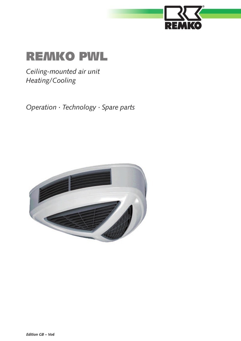
REMKO PWL Series User manual

Operating and
installation instructions
Edition EN - X07 Read the instructions prior to performing any task!
PWL 101-H, PWL 102-H, PWL 103-H, PWL 201-H, PWL 202-H, PWL 203-H
PWL 301-H, PWL 302-H, PWL 303-H, PWL 101-HK, PWL 102-HK, PWL 103-HK
PWL 201-HK, PWL 202-HK, PWL 203-HK, PWL 301-HK, PWL 302-HK, PWL 303-HK
REMKO PWL series
Ceiling-mounted ventilation unit


3
Content
Planning notes 4
Safety notes 4
Unit description 5
Unit installation 6
Installation examples 7
Electrical wiring 8
Hydraulic connection 8
Commissioning 9
Shutdown 10
Care and maintenance 10
Repair 11
Fan motor 12
Condensate pump 12
Unit dimensions 13
Performance tables / technical data PWL 101-103 14
Performance tables / technical data PWL 201-203 16
Performance tables / technical data PWL 301-303 18
Intended use 20
Customer service and guarantee 20
Environmental protection and recycling 20
View of the unit 21
Spare parts list 21
Legend / usable limits 22
Technical data 23
Carefully read this original operating manual prior
to commissioning/using the units!
This manual is an integral part of the unit and must always be kept
in the vicinity of the installation location or on the unit itself.
Subject to modifications. No liability accepted for errors or misprints!

4
REMKO PWL
Safety notes
The units were subjected to
extensive material, functional and
quality inspections prior to delivery.
However, dangers can emanate
from the units if they are used
improperly or not as intended by
untrained personnel.
Always observe the following
safety instructions:
■The respective building code
regulations must be observed as
a basic rule
■The operator is responsible for
the proper unit installation, the
correct electrical installation and
the safe operation of the units
■The units must be set up,
installed and operated in such a
way that no one is endangered
or stressed by radiated heat
■The units may only be fastened
to structures or ceilings made
of construction materials of
sufficient load bearing capacity
■The fastening must take place
with bearing anchors, which are
to be fastened to the unit
■Assembly, connection of the
heating medium, connection
of the electrical system and
the maintenance may only be
carried out by trained, qualified
persons
■The units may not be installed
or operated in potentially
flammable or explosive
environments, or in extremely
dusty / aggressive air
Planning notes
In order to achieve an optimum
comfortable temperature in a
room, the planning of the room
heating or room cooling must
follow some fundamental rules.
Heating mode
The following data is required to
plan the room heating:
■Room heating requirements
QH(kW)
■Basic measurements of the room
(length, width, height)
■Desired air exchange
■Required room temperature
■Required heating medium
temperatures for supply and
return flow
The air outlet temperature of the
units should not fall below 34° C
or exceed 42° C.
If the outlet temperature is below
34 ℃, there is the risk of unpleasant
cool drafts in the work area.
If the outlet temperature is
higher than 42° C, an increased
temperature in the ceiling area
occurs.
The casting distance of the
warm air flow is reduced and
the air in the work area cannot
be sufficiently penetrated by the
warm air flow and mixed.
Undesired "cold air zones" form in
the work area and excessive warm
air pockets form in the ceiling area.
The result is unnecessary heat
losses.
Cooling mode
The following data is required to
plan the room cooling:
■Room cooling load
QH(kW)
■Basic measurements of the room
(length, width, height)
■Required room temperature and
possibly relative humidity
■Required cooling medium
temperatures for supply and
return flow
In order to prevent unpleasant
draughts in the work area, the
air outlet temperature in cooling
mode should be no more than
6 - 8 K below the ambient
temperature.
If the temperature difference is
excessive (> 8 K), unpleasant “cold
air zones“ may form.
The circulated total air quantity of
the units per hour should be 4 to 5
times the room volume so that the
system can react dynamically and
effectively.
If the air circulation is undercut,
the desired room climate control is
very slow-acting and delayed.
In order to prevent the units
dripping, the fan should be set
to the lowest speed and the air
discharge direction should be
selected to be parallel to the
ceiling (horizontal). The medium
temperature may also have to be
adjusted accordingly in order to
reduce condensate dripping.

5
■The units must be installed away
from traffic zones and installed
by crane, for example
■The units may only be operated
in completely assembled
condition
■Safety components (e.g.
protection grids) must not
be removed or rendered
inoperative
■The units may only be used as
intended within the specified
output limits and with the
approved conveying media
■The intake protection grid must
always be free of dirt and loose
objects; the unit outtake may
not be covered or closed
■Never insert foreign objects into
the unit
■The units may not be exposed
to direct jets of water
■Do not operate the units in wet
areas with high humidity (e.g.
automatic car washes, etc.)
■All electrical cables for the
units must be protected against
damage (e.g. by animals etc.)
Unit description
The units are stationary, indirectly
fuelled recirculation cooling/
heating units with Cu/Al finned
heat exchangers for connection
to a pumped cold / hot water
network up to max. 90 °C.
The units have an exclusive
and low design, have universal
applications, and are easy to install
and service.
NOTE
Fault-free function of the units
is only guaranteed if the inlet
temperature at the unit inlet
and the pump performance are
appropriate for the selected
unit classification.
The tube heat exchangers are
made of copper tubes with
aluminium fins on top.
A condensate pump is installed
ready for connection to remove
the condensate that occurs in
cooling mode.
For optimised air guidance,
individually adjustable fins are
installed in the top of the housing
and fins that can be adjusted
completely are installed in the
bottom.
The air discharge direction
(horizontal or vertical) can be
adjusted individually to the on-site
requirements my changing the
fan’s direction of rotation.
The plastic housing can be
removed from the bearing housing
parts by removing the locking bar.
The integrated securing straps
prevent the hood falling down.
The plastic housing on the
units consists of materials that
extinguish themselves in the event
of fire (corresponding to fire class
V-0).
The units conform to the
fundamental health and safety
requirements of the appropriate
EU regulations, and are simple to
operate.
The units are used wherever high
and low-ceilinged rooms have to
be heated or cooled and wherever
great value is placed on exclusivity.
Examples of large rooms include:
■Exhibition halls
■Salesrooms
■Malls
■Business premises
■Warehouses
■Production halls
■Design offices
■Large entrance areas
The units must be installed on
the ceiling or roof structure in
a horizontal position.
The units are equipped with
an aerodynamically designed,
2-speed, high-performance axial
fan with a 400V/50 Hz external
motor.
The inner, load-bearing unit
structure is made of galvanised
steel sheet.
Help by reducing energy
usage in stand-by operation!
If the unit, the system or
the components are not
being used, we recommend
disconnecting the power
supply.
Our recommendation does
not apply to safety relevant
components.
TIP

6
REMKO PWL
For safe unit installation, observe
the following instructions:
■The units are to be arranged
so that people working and
standing near them are not in
the direct air flow
■The units may only be installed
on ceilings or roof structures
with sufficient load-bearing
capacity
■The units must be installed so
that they are level and free of
stress
■The heat exchangers must be
connected in such a way that
no vibrations can be transferred
from the unit to the piping
system or vice versa
■Suitable screw connections,
shut-off valves, bleed valves,
etc. must be installed by the
customer
■The maximum installation
heights of the units must be
observed for ceiling installation
in both low and high-ceilinged
rooms.
■Before connecting the units to
an existing hot water heating
system, the boiler and pump
output must be checked for
sufficient capacity
■A suitable repair switch
(accessory) must be installed for
maintenance and repair work
■The distance between the fan
blade and unit housing must be
checked for an even gap size
Unit installation
Cooling mode
The maximum casting distances
apply for an air outlet temperature
of 8K below the room temperature
and ideal conditions of the primary
air flow.
Maximum installation heights and application limitations
The maximum installation heights depend on the maximum casting
distance and direction.
PWL
Installation height and casting
distance in m with "vertical"
discharge
Installation height and casting
distance in m with "horizontal"
discharge
101-3 3.8 / casting distance 2.3 2.5 / casting distance 3.4
201-3 5.5 / casting distance 4.0 3.8 / casting distance 7.9
301-3 7.0 / casting distance 5.5 5.7 / casting distance 7.0
Heating mode
The maximum installation heights and casting distances (at 0.2 m/s)
apply for an air outlet temperature of 20K above the room temperature
and the ideal conditions of the primary air flow.
PWL Max. casting distance in m
101-3 4.0 1)
201-3 10.0 1)
301-3 9.1 1)
We reserve the right to modify the dimensions and design as part of the ongoing technical development process.
1) Horizontal and vertical discharge direction
Max. installation height
Max. casting distance
Make sure that no one is under the suspended load during installation!
Use the template supplied in the packaging to mark the fastening points.
Ensure that there is sufficient space between the unit and ceiling for the
media connections. Install the unit so that it is insulated against vibration.
The adjustable brackets (optional) can be aligned individually for adjustment.
Fixed bracket (standard) Adjustable bracket (optional)

7
Installation examples
The units are designed for use
in both high and low-ceilinged
rooms.
The fan’s direction of rotation can
be changed (pole switching) in
order to adjust the air direction
individually to the structural or
personal requirements.
Therefore, if the units are used in
low-ceilinged rooms, the air flow
can be controlled horizontally
in the room by the individually
adjustable air discharge fins that
are in the top part of the housing.
This prevents people being
exposed to direct airflow.
Low-ceilinged rooms; horizontal discharge
High-ceilinged rooms; vertical discharge
Combined options for heating and cooling mode
Due to the triangular shape of the units, there are numerous installation arrangements so that even corners can
be supplied in an optimised manner.
Glass façade
Glass façade
Cooling mode
Heating mode
We reserve the right to modify the dimensions and design as part of the ongoing technical development process.

8
REMKO PWL
The electrical unit connections may
only be established by authorised
specialists in accordance with the
applicable regulations, observing
the regulations from the local
energy supplier, as well as the
unit-specific VDE installation
regulations.
Connecting the units
The units are equipped with
2-speed, 400 V, three-phase axial
fans.
The corresponding switchgears
(accessories) are used to switch the
speeds.
The direction of rotation change
is performed by a pole switching
device or a special switchgear
(accessory).
Motor protection is ensured
by integrated thermal contacts
in conjunction with a suitable
switchgear (accessory).
The three-phase motors are
connected to the corresponding
switchgears in accordance with the
corresponding electrical drawings.
Electrical wiring
CAUTION
A failure to observe the
applicable regulations, the
operating manual and the
unit-specific circuit diagrams
can cause malfunctions with
subsequent damage.
Guarantee claims are voided!
CAUTION
When the fan stops, the hy-
draulic feed must also be inter-
rupted at the same time.
CAUTION
The electrical unit connection
may only be established by
trained specialists.
Connection to the on-site
hydraulic system
Before connection to the on-site
hydraulic system, ensure that the
respective unit-specific output
requirements can always be
provided.
■
The water-side unit connection
is to be established by the
customer with appropriate screw
connections for the pipes and
shut-off valves in the supply and
return flow.
We recommend using
compensators and automatic
bleeders!
■
The connection-side is on top
and the supply and return flow
can be connected as required
■
The thread sizes of the pipe
connections are R 1“ inside
thread
■
The finned heat exchangers
must be bled carefully after
installation is complete.
Air pockets in the heat
exchanger cause a reduction in
the heating or cooling capacity!
Hydraulic connection
Water inlet
Water outlet
NOTE
In order to prevent damage
from the connecting pipes
turning, an appropriate tool
must be used to hold them
while connecting the screw
connections for the heating
medium connection.
5 6 78 9 10 11 12 13 14 15 16 17 18 19 20 21 22
W2 U2V2 TK PE
1 3 42
U1V1 W1 TK PE PE N L13 2
Kondensatpumpe
für Kühlbetrieb
CÖS
N
Potenzialfreier Alarmkontakt
1
Kondensatpumpe
Kondensatpumpe
Connecting several units
If required, several units (also of
different sizes) can be operated
in parallel via a switchgear
(accessory).
The total output of the connected
units must not exceed the
maximum switching output of the
corresponding switchgear.
The thermal contacts on all motors
must be switched in sequence for
thermal motor protection. Observe
the special electrical drawings.
Only one external controller
(thermostat, day/night regulation,
etc.) can be connected to each
switchgear!
Connection terminals in the unit
The corresponding power fuse in
the supply line to the switchgear
must be provided by the customer
in accordance with the applicable
regulations.
The connections in the terminal
box must be connected to
the corresponding switchgear
(accessory).
Condensate pump
Condensate pump
Potential-free alarm contact
Condensate pump for cooling
mode

9
Before initial commissioning
■
Check to ensure that
mechanical installation was
performed correctly
■
Check that connection to the
on-site heating system has been
established correctly
■
Check whether hot surfaces are
protected against unintentional
contact
■
Checked whether the electrical
wiring of the units has been
established in accordance with
the applicable directives and
standards, and observing the
enclosed circuit diagrams
■
The fan chamber, the intake
and discharge areas must be
checked for foreign objects
■
The fan's ease of movement
must be checked
■
Disconnect the power supply to
the switchgear (accessory) and
switch on the unit using the
switchgear's control switch
■
Check the fan’s direction of
rotation.
The direction of rotation is
changed by reversing 2 phases
or with an external switchgear
(accessory)
Commissioning
Drainage when at risk of
freezing
Complete static drainage of
the finned heat exchangers is
not possible in the condition as
installed.
If necessary, drainage is only
possible with the assistance of
compressed air.
Important information
regarding anti-freeze protection!
In order to prevent frost damage,
a frost protection device must be
used at temperatures below 0 °C.
In systems that are
decommissioned in rooms at risk of
freezing, the heat exchanger may
never contain "only" water.
The heating medium (water) must
then be supplemented with a
suitable antifreeze with a sufficient
mixture ratio for the environment.
In the process, the hydraulic
output loss must be taken into
account.
■
Note that if using a speed
controller (accessory), the
regulating device output must
be attuned to the total output
of the connected motors
■
Check whether all air discharge
and intake openings are opened
accordingly
CAUTION
Commissioning can only take
place once it has been assured
that the proper assembly
and electrical installation
correspond to the applicable
provisions of the EC Directives.
CAUTION
No guarantee claims can be
accepted for frost damage on
the finned heat exchangers!
Water inlet
Water outlet
Draining the
heating/cooling
medium
Bleeding
Screw connections
The 3 fin segments in the lower
housing part (vertical discharge or
intake) can each be adjusted as a
unit with a louvre.
Air guidance
The fins in the upper side housing
part (horizontal discharge or
intake) can be adjusted individually
in 5 ° increments.

10
REMKO PWL
Switch the operating switch for the
relevant switchgear to the “Off”
or “0” position.
In the event of longer breaks in
operation
■
Disconnect the electrical
connection at all poles
■
Shut off the hydraulic
connection
■
If there is a danger of frost,
the complete system should
be emptied if the heating
medium (water) has not been
mixed with suitable anti-freeze
protection agent
(also see page 9)
Shutdown
Care and maintenance
CAUTION
It is not sufficient to switch off
the unit only via the operating
switch!
During initial commissioning
All regulating, control and safety
equipment must be checked for
function and correct settings
during the initial commissioning.
■
The current consumption of the
fan must be measured.
The rated current may not
exceed the value specified
on the name plate in the
respective switching speeds
■
Check the motor protection
function of the fan
■
Check the entire system for
tension-free installation and
potential vibrations
■
Check the heating/cooling
medium supply lines for proper
connection, tightness and
insulation
■
Ensure that no more
condensate is formed, as
the condensate pump is also
disconnected from the power
supply in this case and is
therefore not functioning
■
Wait until the fan stops
■
Shut off the water circuit and
safeguard it to prevent it being
opened inadvertently
■
Allow the finned heat
exchanger to cool
Cleaning the units
■
Only dry clean the unit surfaces
or clean with a moistened
cloth and some soap solution if
necessary
■
Never use high pressure
cleaners or steam cleaners on
the installed unit
■
Never use abrasive or solvent-
based cleaners
■
Only suitable cleaners may
be used even for heavy
contamination
■
Clean all intake openings and
discharge fins
■
Clean the fan blades. If
required, first remove the motor
or the protection grid
■
Clean the heat exchanger fins
by blowing, with suction or
using a smooth brush
The units are basically
maintenance-free. Perform a visual
inspection on the units and finned
heat exchanger surface every six
months and before the heating
period begins.
If the units are subjected to
excessive dust, perform the
inspections at more regular
intervals.
To do this, remove the 3 locking
bars from the corners of the
bearing unit part to release the
unit’s hood.
Use straps to hold the hood below
the bearing part for inspection.
Undo the strap adjuster on the
straps to remove the hood from
the unit completely if required.
When removing, note that the
suction hose and the probe for the
condensate pump must also be
removed from the bearing part.
Locking bar
Important precautions prior to
maintenance
■
The units should be fully
disconnected (all poles) from
the electrical power supply
and secured to prevent
unauthorised reactivation

11
CAUTION
An electrical safety check must
be carried out in accordance
with VDE 0701 after any work
on the units.
NOTE
Repair and maintenance work
may only be carried out by
authorised and qualified tech-
nicians.
Repair
■
If the finned heat exchanger
surface is coated with greasy or
sooty particles, the exchanger
element can be removed and
cleaned using a steam cleaner
at a low pressure and with
suitable cleaning agents
■
Clean severe soiling on the fan
and the aluminium fins with
soap solution
■
Clean dirt deposits off the
condensate tray in the unit
housing regularly
In order to be able to drain the
condensate tray completely, the
condensate hose’s intake opening
must be affixed to the lowest point
on the hood.
The condensate probe must be
installed slightly above the intake
opening.
Probe lower edge = intake
opening upper edge.
Laying must be performed as
shown in the following illustration.
F = Probe line
K = Condensate hose (inner ø 6)
FK
Replacing the finned heat
exchanger
1. Remove the unit hood
completely.
(see Care and maintenance)
2. Disconnect the fan’s electrical
connection.
3. Disconnect the hydraulic unit
connection.
4. Remove the bottom bearing
plate (6 screws)
5. Remove the bearing plate along
with the finned heat exchanger
in a downwards direction.
6. Install the replacement heat
exchanger and all other
components carefully in reverse
order.
Replacing the fan
1. Remove the unit housing.
(see Care and maintenance)
2. Disconnect the fan’s electrical
connection.
3. Remove the protection grid
along with the fan from the
bearing housing.
4. Install the new fan carefully in
reverse order.
5. Check that the fan blade moves
freely and that there is space
between it and the fan housing.
6. Re-establish the motor’s
electrical connection properly.
CAUTION
Prior to maintenance or repair
work, the unit must be discon-
nected from the mains power
supply and safeguarded to
prevent a restart.
Recommended maintenance intervals in normal unit operation
Check the condensate tray and clean if necessary ½ yearly
Check the condensate drain and clean if necessary ½ yearly
Perform a functional inspection on the condensate pump and the alarm sensor ½ yearly
Check the air grate and clean if necessary Yearly
Check the electrical wiring and grounding Yearly
Clean the finned heat exchanger Yearly
Check the fan for ease of movement and functions Yearly

12
REMKO PWL
We reserve the right to modify the dimensions and design as part of the ongoing technical development process.
hohe Drehzahl
∆ - Schaltung
niedere Drehzahl
Y - Schaltung
TK W2 U2 V2
TK U1 V1 W1
PE L1 L2 L3
TK W2 U2 V2
TK U1 V1 W1
PE L1 L2 L3
400 V / 2-speed fan motor
Condensate pump
Connection diagram
NOTE
All connection terminals of
the electrical wiring are to be
checked for firm seating and
tightened as necessary.
NOTE
Before finally commissioning
the system, test the condensate
pump’s functions based on
the delivery height. Fill water
into the device housing’s
condensate tray and check
that the pump is functioning.
Ensure that the pump switches
off after pumping.
CAUTION
The electrical unit connection
must be established by
authorised specialists in
accordance with DIN EN
60335-1 and VDE 0116.
Standard unit design: ∆/Y switching and thermal contacts.
Max. delivery rate: 50 l/h
Max. delivery height: 20 m
Max. suction height: 7 m
Connection inner Ø: 6 mm
Temperature protection at: 130 °C
0 10 20 30 40 50 60
0
4
8
12
16
20
Förderhöhe in Meter
Liter pro Stunde
The compact condensate pump
must pump out the condensate
that is produced in cooling mode.
The pump is a self-priming rotation
diaphragm pump.
The condensate is pumped out via
a flexible PVC condensate hose
with an inner diameter of 6 mm.
Safety notes:
■
Ensure that the power supply
has been disconnected before
connecting, removing or
replacing the condensate pump
■
Do not use the condensate
pump to pump flammable and
explosive fluids such as petrol,
heating oil, solvents, etc.
■
The condensate pump may
only be used to pump fluids
to which the pump material is
resistant
■
Do not use the condensate
pump in an explosive
atmosphere
■
The electrical wiring must be
established in accordance with
the wiring diagram. Ensure that
the power supply is earthed
in accordance with the legal
regulations
■
Ensure that the condensate
pump is not installed higher
than 7 m (maximum suction
height) above the drip tray
outlet or not lower than 20
m (maximum delivery height)
below the condensate drain’s
peak
Pump controller
Power supply: 230 V/50 Hz
Brown cable: L
Blue cable: N
Green/yellow cable: PE
The pump's power supply must be
fused with a 1 A fine wire fuse.
Potential-free alarm contact:
Black: combined cable
Yellow: Contact closed during operation
and open in the event of an alarm
Red: Contact open during operation and
closed in the event of an alarm
Performance diagram
High speed
Δ - switching
Low speed
Y - switching
Litres per hour
Delivery height in metres

13
We reserve the right to modify the dimensions and design as part of the ongoing technical development process.
NOTE
The supply and return lines can
be connected in any way
Unit dimensions
Dimen-
sions PWL 101-103 HK PWL 201-203 HK PWL 301-303 HK
A 985 mm 1084 mm 1178 mm
B 632 mm 963 mm 1043 mm
C 229 mm 229 mm 229 mm
D 989 mm 1073 mm 1160 mm
H 465 mm 485 mm 504 mm
Condensate pump
The distance between the unit and ceiling must be at least 80 mm!
217
80
44
H
16
90
D
A
C
90
B
B
B
M 8
View "A"
"A"
Condensate hose
Hydraulic connection R 1“
{

14
REMKO PWL
Type PWL 101-H PWL 102-H PWL 103-H
Version 2-speed 2-speed 2-speed
Speed rpm 920 750 920 750 920 750
Electrical connection V 400/3~N
Frequency Hz 50
Power consumption kW 0.1/0.07
Nominal current A 0.26/0.13
Air volume m³/h 2030 1685 1960 1610 1885 1530
Sound pressure level 1)
dB (A) 56 47 56 47 56 47
Sound power level dB 64 55 64 55 64 55
Max. installation height
m 2.8 2.7 2.5
Max. casting distance 2)
m 3.4 3.2 3.0
Hydraulic connection Inches R 1“ R 1“ R 1“
Water volume l 1.0 1.6 2.5
Weight kg 31 35 38
PWW heating medium
tL1
°C kW tL2
°C kW tL2
°C kW tL2
°C kW tL2
°C kW tL2
°C kW tL2
°C
45/38 °C
0 8.2 12 7.4 13 13.4 20 12.0 22 17.5 27 15.0 29
5 7.2 15 6.4 16 11.8 23 10.5 24 15.3 29 13.2 30
10 6.2 19 5.5 20 10.1 25 9.1 27 13.2 30 11.3 32
15 5.1 22 4.6 23 8.4 28 7.6 29 11.0 32 9.5 33
20 4.1 26 3.7 26 6.7 30 6.1 31 8.8 34 7.6 35
50/40 °C
0 8.8 13 7.9 14 14.4 22 13.0 24 18.8 29 16.2 31
5 7.8 16 7.0 17 12.8 24 15.5 26 16.7 31 14.4 33
10 6.8 20 6.1 21 11.1 27 10.0 28 14.5 33 12.5 34
15 5.7 23 5.1 24 9.4 29 8.5 30 12.3 34 10.6 35
20 4.7 27 4.2 27 7.7 32 7.0 33 10.1 36 8.7 37
55/45 °C
0 9.9 14 8.8 15 16.1 24 14.5 26 21.1 33 18.1 35
5 8.9 18 7.9 19 14.5 27 13.0 29 18.9 34 16.3 36
10 7.8 21 7.0 22 12.8 29 11.5 31 16.7 36 14.4 38
15 6.8 25 6.1 26 11.1 32 10.0 33 14.6 38 12.5 39
20 5.8 28 5.2 29 9.5 34 8.5 36 12.4 39 10.7 40
60/45 °C
0 10.2 15 9.1 16 16.7 25 15.0 27 21.9 34 18.8 36
5 9.2 18 8.2 19 15.1 28 13.5 30 19.7 36 17.0 38
10 8.1 22 7.3 23 13.4 30 12.0 32 17.5 37 15.1 39
15 7.1 25 6.4 26 11.7 33 10.5 34 15.3 39 13.2 40
20 6.1 29 5.4 29 10.0 35 9.0 36 13.1 40 11.3 42
70/50 °C
0 11.6 17 10.4 18 19.1 29 17.1 31 24.9 39 21.5 41
5 10.6 20 9.5 22 17.4 31 15.6 34 22.8 40 19.6 43
10 9.5 24 8.5 25 15.7 34 14.1 36 20.5 42 17.8 44
15 8.5 27 7.6 28 14.0 36 12.6 38 18.3 44 15.9 45
20 7.4 31 6.7 32 12.3 38 11.1 40 16.1 45 14.0 47
PWL 101-103 - Heating • Performance tables • Technical data
We reserve the right to modify the dimensions and design as part of the ongoing technical development process.
tL1 = air inlet temperature / tL2 = air outlet temperature
2) at ∆t20 K (Air inlet to air outlet temperature difference)
Operating method with limitation of the casting distance

15
tL1 = air inlet temperature / tL2 = air outlet temperature
Type PWL 101-HK PWL 102-HK PWL 103-HK
Version 2-speed 2-speed 2-speed
Speed rpm 920 750 920 750 920 750
Electrical connection 400/3~N
Frequency Hz 50
Power consumption kW 0.1/0.07
Nominal current A 0.26/0.13
Air volume m³/h 2030 1685 1960 1610 1885 1530
Sound pressure level
1)
dB (A) 56 47 56 47 56 47
Sound power level dB 64 55 64 55 64 55
Hydraulic connection
Inches R 1“ R 1“ R 1“
Water volume l 1.0 1.6 2.5
Max. condensate
accumulation l/h 2.8 2.6 4.3 4.1 6.3 5.7
Weight kg 31 35 38
Motor vehicle
refrigerant
tL1 QgQstL2 QgQstL2 QgQstL2 QgQstL2 QgQstL2 QgQstL2
°C kW kW °C kW kW °C kW kW °C kW kW °C kW kW °C kW kW °C
5/10 °C
23 3.5 3.4 19 3.1 3.5 19 5.8 3.5 16 5.1 3.5 16 8.4 3.5 14 7.2 13 13
25 3.9 20 3.5 20 6.5 17 5.8 17 9.4 15 8.0 14 14
26 3.7 21 3.3 21 6.0 18 5.3 17 8.7 15 7.4 14 14
27 4.1 22 3.7 21 6.7 18 6.0 18 9.7 15 8.3 15 15
32 5.4 25 4.9 25 8.9 21 7.9 20 12.5 17 10.8 16 16
7/12 °C
23 2.7 20 2.4 19 4.5 17 4.0 17 6.7 15 5.8 15 15
25 3.2 21 2.9 21 5.2 18 4.7 18 7.7 16 6.6 15 15
26 3.0 22 2.7 21 4.8 19 4.3 18 7.1 16 6.1 16 16
27 3.4 22 3.0 22 5.6 19 4.9 19 8.1 17 7.0 16 16
32 4.7 26 4.2 25 7.7 22 6.8 21 10.8 18 9.4 18 18
9/14 °C
23 2.0 20 1.8 20 3.3 18 2.9 18 5.1 16 4.4 16 16
25 2.4 22 2.2 21 4.0 19 3.6 19 6.1 17 5.2 17 17
26 2.7 22 2.4 22 4.4 20 3.9 19 6.2 17 5.3 17 17
27 2.7 23 2.4 23 4.4 20 3.9 20 6.4 18 5.6 17 17
32 3.9 26 3.5 26 6.4 23 5.7 22 9.2 20 8.0 19 19
11/16 °C
23 1.6 21 1.4 21 2.6 19 2.3 19 3.9 17 3.4 17 17
25 1.9 22 1.7 22 3.1 20 2.7 20 4.4 18 3.9 18 18
26 2.2 23 1.9 23 3.5 21 3.1 20 4.7 18 4.1 18 18
27 2.4 23 2.2 23 3.9 21 3.5 21 5.5 19 4.8 18 18
32 3.3 27 2.9 27 5.2 24 4.7 23 7.6 21 6.6 20 20
13/18 °C
23 1.2 21 1.0 21 1.9 20 1.7 20 2.7 19 2.3 18 18
25 1.6 23 1.4 23 2.6 21 2.3 21 3.5 19 3.0 19 19
26 1.8 23 1.6 23 2.9 22 2.5 21 3.9 20 3.4 19 19
27 2.0 24 1.8 24 3.2 22 2.8 22 4.3 20 3.7 20 20
32 3.1 27 2.7 27 5.0 24 4.4 24 7.2 22 5.8 21 21
PWL 101-103 - Cooling • Performance tables • Technical data
We reserve the right to modify the dimensions and design as part of the ongoing technical development process.
1)
LpA 1m,
Noise level measurement DIN 45635 - 01 - KL 3

16
REMKO PWL
Type PWL 201-H PWL 202-H PWL 203-H
Version 2-speed 2-speed 2-speed
Speed rpm 920 750 920 750 920 750
Electrical connection V 400/3~N
Frequency Hz 50
Power consumption kW 0.28/0.18
Nominal current A 0.67/0.37
Air volume m³/h 3110 2580 2900 2400 2850 2350
Sound pressure level 1)
dB (A) 61 53 61 56 61 56
Sound power level dB 69 61 69 64 69 64
Max. installation height
m 5.5 5.3 5.2
Max. casting distance
2)
m 7.9 5.8 5.0
Hydraulic connection Inches R 1“ R 1“ R 1“
Water volume l 1.0 1.8 2.9
Weight kg 32 35 38
PWW heating medium
tL1
°C kW tL2
°C kW tL2
°C kW tL2
°C kW tL2
°C kW tL2
°C kW tL2
°C
45/38°C
0 10.6 10 9.5 11 18.2 18 16.1 20 23.5 24 20.5 26
5 9.2 14 8.2 14 16.0 21 14.1 22 20.6 26 17.9 27
10 7.8 17 7.0 18 13.7 24 12.1 25 17.7 28 15.4 29
15 6.3 21 5.7 21 11.4 27 10.1 27 14.8 30 12.9 31
20 4.9 25 4.4 25 9.2 29 8.1 30 11.9 32 10.3 33
50/40°C
0 11.2 11 10.0 11 19.6 20 17.3 21 25.3 26 22.1 28
5 9.7 14 8.7 15 17.4 23 15.3 24 22.4 28 19.5 29
10 8.3 18 7.4 18 15.1 25 13.3 26 19.5 30 17.0 31
15 6.8 21 6.2 22 12.8 28 11.3 29 16.6 32 14.5 33
20 5.4 25 4.9 26 10.5 31 9.3 31 13.6 34 11.9 35
55/45°C
0 12.7 12 11.4 13 21.9 22 19.3 24 28.3 29 24.7 31
5 11.2 16 10.1 16 19.7 25 17.3 26 25.4 31 22.1 33
10 9.8 19 8.8 20 17.4 28 15.3 29 22.5 33 19.6 35
15 8.4 23 7.5 24 15.1 30 13.4 31 19.6 35 17.1 36
20 6.9 27 6.2 27 12.9 33 11.4 34 16.6 37 14.5 38
60/45°C
0 12.6 12 11.4 13 22.7 23 20.1 25 29.4 30 25.6 32
5 11.2 16 10.1 16 20.5 26 18.1 27 26.5 32 23.1 34
10 9.8 19 8.8 20 18.2 28 16.1 30 23.5 34 20.6 36
15 8.3 23 7.5 24 15.9 31 14.1 32 20.6 36 18.0 37
20 6.9 27 6.2 27 13.6 34 12.0 35 17.6 38 15.4 39
70/50°C
0 14.2 13 12.7 15 25.9 26 22.9 28 33.5 35 29.3 37
5 12.8 17 11.5 18 23.6 29 20.9 31 30.6 37 26.7 38
10 11.3 21 10.2 22 21.3 32 18.9 33 27.6 39 24.1 40
15 9.9 24 8.9 25 19.1 34 16.8 36 24.7 40 21.6 42
20 8.5 28 7.6 29 16.8 37 14.8 38 21.7 42 19.0 44
We reserve the right to modify the dimensions and design as part of the ongoing technical development process.
PWL 201-203 - Heating • Performance tables • Technical data
tL1 = air inlet temperature / tL2 = air outlet temperature
2) at ∆t20 K (Air inlet to air outlet temperature difference)
Operating method with limitation of the casting distance

17
Type PWL 201-HK PWL 202-HK PWL 203-HK
Version 2-speed 2-speed 2-speed
Speed rpm 920 750 920 750 920 750
Electrical connection V 400/3~N
Frequency Hz 50
Power consumption kW 0.28/0.18
Nominal current A 0.67/0.37
Air volume m³/h 3110 2580 2900 2400 2850 2350
Sound pressure level 1)
dB (A) 61 53 61 56 61 56
Sound power level dB 69 61 69 64 69 64
Hydraulic connection Inches R 1“ R 1“ R 1“
Water volume l 1.0 1.8 2.9
Max. condensate
accumulation l/h 2.3 2.2 5.6 5.2 7.6 7.1
Weight kg 32 35 38
Motor vehicle refrigerant
tL1/r.F.
°C/% kW tL2/r.F.
°C/% kW tL2/r.F.
°C/% kW tL2/r.F.
°C/% kW tL2/r.F.
°C/% kW tL2/r.F.
°C/% kW tL2/r.F.
°C/%
5/10 °C
23 3.3 20 3.0 20 8.2 17 7.3 16 11.0 15 9.7 14
25 3.9 22 3.6 21 9.2 18 8.3 17 12.3 16 10.9 15
26 3.8 22 3.4 22 8.5 18 7.6 18 11.4 16 10.1 15
27 4.2 23 3.8 23 9.5 19 8.5 18 12.8 16 11.3 16
32 5.9 27 5.3 26 12.4 21 11.1 21 16.8 18 14.8 18
7/12 °C
23 2.5 21 2.3 20 6.4 18 5.8 17 8.7 16 7.7 16
25 3.0 22 2.8 22 7.4 19 6.7 18 10.0 17 8.9 16
26 3.3 23 3.0 23 6.9 19 6.2 19 9.3 17 8.3 17
27 3.6 24 3.2 23 7.8 20 7.0 19 10.6 18 9.4 17
32 5.0 27 4.5 27 10.7 22 9.6 22 14.5 20 12.8 19
9/14 °C
23 2.0 21 1.8 21 4.7 18 4.3 18 6.5 17 5.7 17
25 2.6 23 2.3 22 5.7 20 5.2 19 7.8 18 7.0 17
26 2.9 23 2.6 23 6.4 20 5.7 19 8.2 18 7.2 18
27 3.1 24 2.8 24 6.2 21 5.6 20 8.5 19 7.5 18
32 4.4 28 4.0 27 9.0 23 8.1 23 12.3 21 10.9 20
11/16 °C
23 1.6 22 1.4 21 3.9 19 3.4 19 4.9 18 4.4 18
25 2.1 23 1.9 23 4.5 20 3.9 20 5.7 19 5.1 19
26 2.4 24 2.1 24 5.0 21 4.4 21 6.4 19 5.6 19
27 2.6 24 2.4 24 5.7 21 5.1 21 7.3 20 6.4 19
32 3.9 28 3.5 28 7.4 24 6.6 24 10.1 22 8.8 21
13/18 °C
23 1.2 20 1.1 19 2.8 20 2.5 20 3.6 19 3.1 19
25 1.6 23 1.4 23 3.7 21 3.3 21 4.7 20 4.1 20
26 1.9 24 1.7 24 4.1 22 3.7 21 5.3 20 4.6 20
27 2.1 25 1.9 25 4.1 22 3.7 21 5.3 20 4.6 20
32 3.5 29 3.1 28 7.1 25 6.3 24 9.1 23 8.0 22
We reserve the right to modify the dimensions and design as part of the ongoing technical development process.
PWL 201-203 - Cooling • Performance tables • Technical data
tL1 = air inlet temperature / tL2 = air outlet temperature
1)
LpA 1m,
Noise level measurement DIN 45635 - 01 - KL 3

18
REMKO PWL
Type PWL 301-H PWL 302-H PWL 303-H
Version 2-speed 2-speed 2-speed
Speed rpm 920 750 920 750 920 750
Electrical connection 400/3~N
Frequency Hz 50
Power consumption kW 0.36/0.22
Nominal current A 0.84/0.46
Air volume m³/h 4300 2650 4150 2400 3900 1710
Sound pressure level 1)
dB (A) 66 59 66 59 68 61
Sound power level dB 74 69 74 69 76 69
Max. installation height
m 7.0 6.5 6.0
Max. casting distance 2)
m 5.0 7.0 6.2
Hydraulic connection Inches R 1“ R 1“ R 1“
Water volume l 1.1 2.0 3.3
Weight kg 43 46 48
PWW heating medium
tL1
°C kW tL2
°C kW tL2
°C kW tL2
°C kW tL2
°C kW tL2
°C kW tL2
°C
45/38°C
0 13.8 9 10.3 11 22.3 16 15.9 19 30.5 23 17.2 29
5 12.0 13 8.9 15 19.3 19 13.8 22 26.7 25 15.1 31
10 10.1 17 7.6 18 16.4 22 11.7 24 23.0 27 13.0 32
15 8.3 21 6.2 22 13.4 24 9.6 27 19.2 29 10.9 34
20 6.4 24 4.8 25 10.4 27 7.5 29 15.4 32 8.8 35
50/40°C
0 14.5 10 10.9 12 23.5 17 16.8 21 32.9 25 18.6 32
5 12.7 14 9.5 16 20.5 20 14.7 23 29.1 27 16.5 33
10 10.9 17 8.1 19 17.6 22 12.6 25 25.3 29 14.4 35
15 9.0 21 6.8 23 14.7 25 10.5 28 21.5 31 12.3 36
20 7.2 25 5.4 26 11.7 28 8.4 30 17.7 33 10.2 38
55/45°C
0 16.5 11 12.3 14 26.7 19 19.0 23 36.7 28 20.7 35
5 14.7 15 10.9 17 23.7 22 16.9 26 32.9 30 18.6 37
10 12.8 19 9.6 21 20.7 25 14.8 28 29.2 32 16.5 38
15 11.0 22 8.2 24 17.8 28 12.7 31 25.4 34 14.4 40
20 9.1 26 6.8 28 14.8 30 10.6 33 21.6 36 12.3 41
60/45°C
0 16.5 11 12.3 14 26.8 19 19.1 23 38.1 29 21.7 37
5 14.7 15 11.0 17 23.8 22 17.1 26 34.3 31 19.6 38
10 12.8 19 9.6 21 20.8 25 14.9 28 30.6 33 17.5 40
15 11.0 22 8.2 24 17.9 28 12.9 31 26.8 35 15.3 41
20 9.1 26 6.9 28 15.3 31 11.2 33 22.9 37 13.2 43
70/50°C
0 18.6 13 13.9 15 30.2 21 21.6 26 43.5 33 24.8 42
5 16.7 16 12.5 19 27.2 24 19.5 29 39.7 35 22.7 44
10 14.9 20 11.2 22 24.2 27 17.4 31 35.9 37 20.5 45
15 13.0 24 9.8 26 21.5 30 15.6 34 32.1 39 18.4 47
20 11.2 28 8.4 29 18.5 33 13.4 37 28.2 41 16.3 48
We reserve the right to modify the dimensions and design as part of the ongoing technical development process.
PWL 301-303 - Heating • Performance tables • Technical data
tL1 = air inlet temperature / tL2 = air outlet temperature
2) at ∆t20 K (Air inlet to air outlet temperature difference)
Operating method with limitation of the casting distance

19
Type PWL 301-HK PWL 302-HK PWL 303-HK
Version 2-speed 2-speed 2-speed
Speed rpm 920 750 920 750 920 750
Electrical connection 400/3~N
Frequency Hz 50
Power consumption kW 0.36/0.22
Nominal current A 0.84/0.46
Air volume m³/h 4300 2650 4150 2400 3900 1710
Sound pressure level
1)
dB (A) 66 59 66 59 68 61
Sound power level dB 74 69 74 69 76 69
Hydraulic connection Inches R 1“ R 1“ R 1“
Water volume l 1.1 2.0 3.3
Max. condensate
accumulation l/h 3.0 2.7 4.2 4.1 9.5 6.7
Weight kg 43 46 48
Motor vehicle refrigerant
tL1/r.F.
°C/% kW tL2/r.F.
°C/% kW tL2/r.F.
°C/% kW tL2/r.F.
°C/% kW tL2/r.F.
°C/% kW tL2/r.F.
°C/% kW tL2/r.F.
°C/%
5/10 °C
23 4.5 20 3.5 20 7.4 18 5.6 17 14.3 15 8.4 13
25 5.2 22 4.1 21 8.6 20 6.5 18 16.0 16 9.4 14
26 5.0 23 3.8 22 8.1 20 6.0 19 14.8 17 8.6 14
27 5.5 23 4.4 22 9.1 21 6.9 19 16.6 17 9.7 14
32 7.7 27 6.0 26 12.6 24 9.5 22 21.7 19 12.6 16
7/12 °C
23 3.3 21 2.6 20 5.4 19 4.2 18 11.3 16 6.6 14
25 4.0 22 3.2 22 6.6 20 5.1 19 13.1 17 7.7 15
26 4.4 23 3.3 22 7.1 21 5.1 20 12.2 18 7.1 15
27 4.7 24 3.5 23 7.7 21 5.5 20 13.8 18 8.1 16
32 6.5 27 5.1 26 10.6 24 8.0 23 18.8 20 10.9 17
9/14 °C
23 2.7 21 2.1 21 4.4 20 3.2 19 8.4 17 5.0 16
25 3.4 23 2.6 22 5.5 21 4.0 20 10.2 18 6.0 16
26 3.8 23 2.9 23 6.3 21 4.5 20 10.7 18 6.1 16
27 4.1 24 3.1 23 6.6 22 4.7 21 11.1 19 6.5 17
32 5.8 28 4.3 27 9.4 25 6.6 23 16.0 21 9.3 18
11/16 °C
23 2.1 22 1.6 21 3.5 20 2.5 20 6.5 18 3.8 17
25 2.7 23 2.1 23 4.5 22 3.2 21 7.5 19 4.4 18
26 3.1 24 2.4 23 5.2 22 3.7 21 8.3 20 4.7 18
27 3.5 25 2.6 24 5.7 23 4.1 22 9.6 20 5.4 18
32 5.1 28 3.9 28 8.3 26 5.9 24 13.2 22 7.7 20
13/18 °C
23 1.5 22 1.1 22 2.6 21 1.8 20 4.7 19 2.7 18
25 2.1 24 1.6 23 3.5 22 2.6 22 6.2 20 3.5 19
26 2.5 24 1.9 24 4.1 23 3.0 22 6.9 21 3.9 19
27 2.8 25 2.1 25 4.7 24 3.3 23 7.7 21 4.3 19
32 4.6 29 3.4 28 7.5 26 5.3 25 11.9 23 6.7 21
We reserve the right to modify the dimensions and design as part of the ongoing technical development process.
PWL 301-303 - Cooling • Performance tables • Technical data
tL1 = air inlet temperature / tL2 = air outlet temperature
1)
LpA 1m,
Noise level measurement DIN 45635 - 01 - KL 3

20
REMKO PWL
The units are designed exclusively
for heating and cooling purposes
in industrial or commercial use on
the basis of their structural design
and equipment.
The units must only be operated
by appropriately instructed
personnel.
The manufacturer shall not
be liable for damage resulting
from non-observance of the
manufacturer's specifications, the
respective local legal requirements
or from unauthorised alterations to
the units.
Customer service and
guarantee
As a prerequisite for any
guarantee claims to be considered,
it is essential that the ordering
party or their representative
complete and return the
“Certificate of guarantee” to
REMKO GmbH & Co. KG at the
time when the units are purchased
and commissioned.
The units were tested at the
factory
several times to verify their correct
function.
However, if malfunctions should
arise that cannot be remedied by
the operator with the assistance of
the troubleshooting section, please
contact your specialist dealer or
contractual partner.
Intended use
Disposal of packaging
When disposing of packaging
material, please consider our
environment.
Our units are carefully packed
and delivered in stable transport
packaging and, if applicable,
on a wooden pallet.
The packaging materials are
environmentally-friendly and can
be recycled.
By recycling packaging materials,
you make a valuable contribution
to the reduction of waste and
conservation of raw materials.
Therefore, only dispose of
packaging material at appropriate
collection points.
Disposal of the old unit
The manufacturing process for
the units is subject to continuous
quality control.
Only high-grade materials are
processed, the majority of which
are recyclable.
You also contribute to
environmental protection by
ensuring that your old equipment
is only disposed of in an
environment friendly manner.
Therefore, only bring the old
unit to an authorised recycling
business or to an appropriate
collection point
.
NOTE
Operation that differs from
that specified in this operating
manual is prohibited.
Failing to observe this renders
any manufacturer liability or
guarantee claims void.
NOTE
Adjustment and maintenance
work may only be carried
out by authorised specialist
personnel.
Environmental
protection and
recycling
CAUTION
Copyright
The redistribution, even
in part, or the use of this
documentation for purposes
other than intended is
prohibited without the written
authorisation of
REMKO GmbH & Co. KG
.
Other manuals for PWL Series
1
This manual suits for next models
15
Table of contents
Other REMKO Fan manuals
Popular Fan manuals by other brands

Hitachi
Hitachi RCIM-0.4FSRE Installation & operation manual

QUORUM INTERNATIONAL
QUORUM INTERNATIONAL Mykonos 72" installation instructions

Maico
Maico ECA 150 ipro Mounting and operating instructions

Awenta
Awenta CM operating manual

HOME ELEMENT
HOME ELEMENT HE-FN1205 user manual

Ruck Ventilatoren
Ruck Ventilatoren DHA 190 E2P 01 Assembly instruction