5
Description
Warranty
The warranty conditions are listed in the
"General terms and conditions".
Please contact your contractual partner
in the first instance.
Environmental pro-
tection and recycling
Disposing of packaging
All products are packed for transport
in environmentally friendly materials.
You can make a valuable contribution
to reducing waste and sustaining raw
materials by only disposing of packaging
at approved collection points.
Disposal of
components
The manufacturing process for the
units is subject to continuous qual-
ity control. Only high-grade materials are
processed, the majority of which
are recyclable. You can also
contribute to environmental protec-
tion by only disposing of components
in accordance with local regulations and
in an environmentally safe manner, e.g.
through authorised disposal and recycling
specialists or at collection
points.
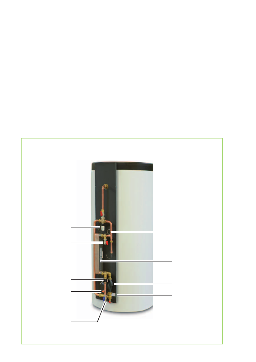
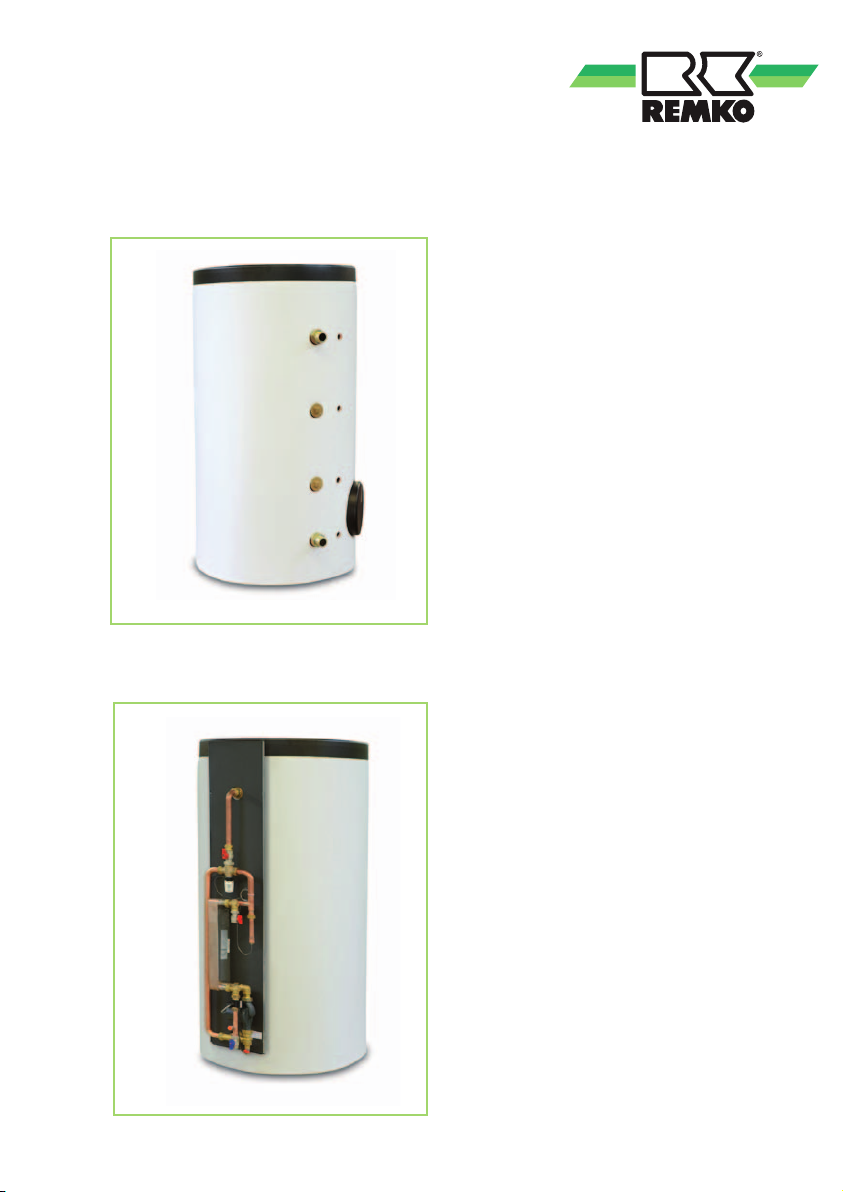
The fresh water station was developed
for use by regenerative heating appli-
ances, particularly for heat pumps. It can
supply one to two residential units with
fresh domestic hot water.
The domestic hot water is only heated
when there is demand, via a stainless
steel plate heat exchanger, in a hygienic
flow process.
The energy supply required for this is
provided as needed by a heating water
storage tank.
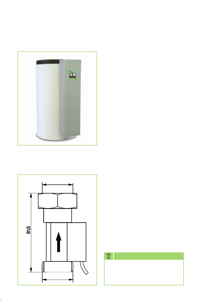
When the hot tap is opened, the in-
tegrated circulation pump is switched
on by a flow switch and heating water
is conveyed from the heating water
storage tank to the primary side of the
stainless steel plate heat exchanger,
causing the cold drinking water flowing
Intended use
The fresh water station was developed
for use by regenerative heating appli-
ances, particularly for heat pumps.
The domestic hot water is only heated
when there is demand, via a stainless
steel plate heat exchanger, in a hygienic
flow process.
The energy supply required for this is
provided as needed by a heating water
storage tank.SFlb
Any alternative or ad-
ditional use is classed as non-intended
use. The manufacturer/supplier assumes
no liability for damages arising from such
use. The user bears the sole risk in such
cases.
Intended use also includes working in ac-
cordance with the operating manual and
installation instructions and complying
with the maintenance requirements.