Remotec Z-Thermostat ZTS-100 User manual

1
ZTS-100
(Z-Thermostat)

2
Table of Contents
Introduction ....................................................................3
Features list ............................................................... 3
Glossary ..........................................................................5
Physical Installation and Wiring ....................................6
Installation Location .................................................... 6
Wiring ....................................................................... 6
Jumper settings for ELECTH-HPUMP and HE-HG .............. 8
Mounting ................................................................... 9
ZTS-100 Z-Thermostat Operations .................................10
Configurations ........................................................... 10
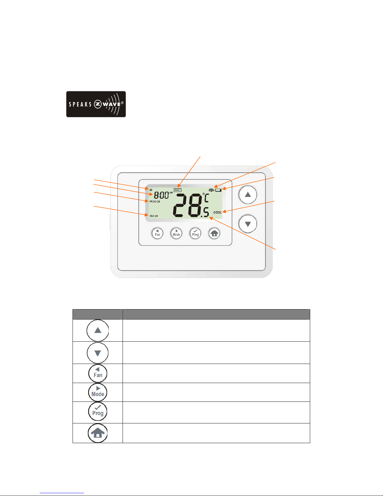
Description of Function Keys ......................................... 10
Normal Operation Mode .................................................11
Change Operation mode .............................................. 11
Select Fan mode ......................................................... 12
Select Program mode .................................................. 12
Override/Permanent Override ....................................... 13
Setting Mode ...................................................................14
Setting schedule ............................................................16
Z-Wave Add (Inclusion) / Delete (Exclusion) Mode .......18
Delete ZTS-100 from Gateway / Controller Z-Wave network19
Add ZTS-100 to Gateway / Controller Z-Wave network ..... 19
Filter counter .................................................................20
Reset ZTS-100 to factory default settings ......................21
Battery Low indication ...................................................22
Defrost indication ...........................................................22
Out of temperature range indication ..............................22
Advance Recovery indication ..........................................23
Short cycle start up protection .......................................24
FREQUENTLY ASKED QUESTIONS ...................................24
TECHNICAL SPECIFICATIONS .........................................26
CHECKING THE ACCESSORIES ........................................27
FCC NOTICE ....................................................................27
WARNINGS .....................................................................27

3
ZTS-100 Z-Thermostat
Introduction
Welcome to the Z-Wave world of home automation, your ZTS-100 Z-Thermostat (Figure 1) is a
comfort control master that allow to control your room temperature with programmable time
schedule WAKE, AWAY, HOME and SLEEP event which can maximize energy conservation and
comfort while minimizing the effort required to maintain the appropriate temperature in your home
whether you are at home or away.
Also, it is allow to control / check your room temperature by the smart phone or PC while you are at
office, home anywhere or around the world which can go through the Z-Wave gateway control.
ZTS-100 also supports batteries operation that can provide flexibility if there is out of 24VAC power
line.
Figure 1. ZTS-100
Features list
HVAC System Type Compatible:
zStandard (gas/electric) or Heat Pump
Multistage System Compatible:
zStandard HVAC Systems: 2 stage heating, 1 stage cooling
zHeat Pump Systems: 1 stage heating, 1 stage cooling

4
Heat Pump change over valve:
zSelectable change over with cool or with heat
Power:
zPowered by alkaline batteries AA x 4pcs or 24Vac
Program Style:
z2 program modes for scheduling (Mo-Fr, Sa-Su)
z4 Separate Time and Temperature Settings for each program
zHeat and Cool set-points for each program
zTemporary Program Override
zPermanent Program Override
zBuilt-in flash memory stores heat and cool program settings
Temperature Display and Control:
zTemperature display in °F or °C
zTemperature Measurable Range: 32 – 99 °F / 0 – 40 °C
zTemperature Setting Range: 41-99 °F / 5-37 °C
zAdjustable Temperature Control Swing/Differential
a) Swing: 1°F, 2°F, 3°F or 4°F ( 0.5°C, 1.0°C, 1.5°C or 2°C)
b) Differential: 1°F, 2°F, 3°F or 4°F ( 0.5°C, 1.0°C, 1.5°C or 2°C)
zAdvance Recovery Mode (ARM)
zDefrost Function
zShort cycle start up protection
Clock:
zTime display format: 12/24 hour clock selection with day displayed
Filter Counter:
zCounts up to 999 days
zFilter change reminder displayed after 500 hours usage
Others
zBattery Low Indicator
zWhite LCD Backlight

5
Glossary
Device or Node
Devices and nodes are all terms to describe an individual Z-Wave
device. These are all interchangeable when setting up your Z-Wave
network.
Inclusion Add a Z-Wave device to the network.
Exclusion Delete a Z-Wave device from the network.
Remove To take a device out of a group, scene or association group while
that device still exists in the same Z-Wave network.
Z-Wave Network
A collection of Z-Wave devices controlled by primary and
secondary controllers operating on the same system. A Z-Wave
network has its own unique ID code so that controllers not in the
network cannot control the system.
Primary Controller
The first controller used to set up your devices and network. Only
the Primary Controller can be used to include or delete devices
from a network. It is recommended that you mark the primary
controller for each network for ease in modifying your network.
Secondary Controller
A controller containing network information about other devices
within the network and is used for controlling devices. Secondary
controllers are created from the Primary Controller and cannot
include or delete devices to the network.
Inclusion Controller
A controller containing network information about other devices
within the network and is used for controlling devices. Inclusion
controllers are created from the Primary Controller in a SIS enabled
Z-Wave network. Inclusion Controller has the ability to add and
remove devices from the network.
Scene
A collection of Z-Wave devices configured to turn to a specific
level, setting, mode, or perform an operation. Scenes are usually
activated by a controller, timed event, or specific conditions.

6
Physical Installation and Wiring
LCAUTION
−Read the enclosed instructions carefully before installing your new Z-Thermostat. Pay close
attention to all warnings and notes and carefully follow the installation steps in the order they
are presented to save time and minimize the risk of damaging the thermostat or the system it
controls.
−Turn off ZTS-100 and the electronic devices (e.g. heater, cooler) which will be connected and
the electric source before installation and maintenance. It is highly recommended that the
installation procedure is processed by trained personnel.
Battery safety!
−Use new batteries of the recommended type and size only.
−Never mix used and new batteries together.
−To avoid chemical leaks, remove batteries from the ZTS-100 if you do not intend to use the
unit for an extended period of time.
−Dispose of used batteries properly; do not burn or bury them.
Installation Location:
The Thermostat is restricted to be used in indoor only. It should be mounted on an inner wall about
1.5m above the floor at a position where it is readily affected by changes of the general room
temperature with freely circulating air. Avoid mounting above or near hot surfaces or equipment (e.g.
TV, heater, refrigerator). Avoid mounting where it will be exposed to direct sunshine, drafts, or in a
laundry room or other enclosed space. Do not expose this unit to dripping or splashing.
Wiring:
zBe sure the operation mode is OFF and Fan selection is Fan Auto
zWire the proper cables at the terminal block according to the circuit diagram
zAfterward, push all cables back into the wall
zDo not use metal conduit or of cable provided with a metal sheath
zRecommends adding fuse or protective device in the line circuit
Terminals Symbol
Cool changeover (heat pump) O
Heat changeover (heat pump) B
2nd Stage heater W2
1st Stage heater W1
Fan G
Compressor Y
24VAC Return for Cooling call switch power RC
24VAC Return for Heat call switch power RH
24VAC Common C

7
Important!
The ZTS-100 can be powered by alkaline batteries AA x 4pcs or 24Vac.
Connect the “24VAC Common” (typically the Blue wire/terminal) and “24VAC Return” (typically
the Red wire/terminal) from the HVAC system to the ZTS-100 HVAC System terminal block “C”
and “RH” or “RC” terminals (the RH and RC terminals are default tied together).
Common or Split Transformer Systems:
Most HVAC systems have a common heating and cooling transformer. A wire is connected to tie the
RH and RC inputs together for this configuration. If you have a system with separate heating and
cooling transformers, you will need to disconnect the RH and RC wire.
When wiring split systems, wire the heating systems “24VAC Return” (red wire) to the ZTS-100
“RH” terminal, and wire the cooling systems “24VAC Return” to the ZTS-100 “RC” terminal. Also
wire the cooling systems “24VAC Common” to the ZTS-100 “C” terminals.
Note: Do not split RC/RH for Heat Pump systems!
Figure 2. Non-heat pump (Standard Gas or Electric) HVAC system wiring
Figure 3. Heat pump system wiring
O
B
W2
W1
G
Y
RC
RH
C C - 24VAC Common
R - 24VAC Return
Y - Compressor
G - Fan
W1 – 1st stage heater
W2 – 2nd stage heater
Blue
Red
Yellow
Green
White
Orange
Standard HVAC System
O
B
W2
W1
G
Y
RC
RH
C C - 24VAC Common
R - 24VAC Return
Y - Compressor
G - Fan
W2 – 2nd stage heater
Blue
Red
Yellow
Green
Orange
O - Cool changeover (heat pump)
Heat Pump HVAC System
ZTS-100
B - Heat changeover (heat pump)

8
Jumper settings for ELECTH-HPUMP and HE-HG:
Jumper Function Description
Set to ELECTH for non heat pump system
Set to HPUMP for heat pump system
Set to HG for Gas heat-fan controlled unit
Set to HE for Electrical heat-fan controlled unit

9
Mounting:
1. Open the ZTS-100 by pushing the hook (Figure 5)
2. Install AAx4pcs batteries if using battery power (Alkaline batteries are recommended)
3. Check the polarity of the batteries and the "+/-" marks inside the battery compartment
4. Connect 24Vac common at C terminal if using 24Vac power
5. Place the cables at the hole near the terminal block
6. Insert 2 pieces of wall anchors into the holes of the wall
7. Fasten the thermostat with 2 pieces of long screws through the 2 mounting holes (Figure 6)
8. Install the top housing by hooking the bottom (Figure 6)
Figure 5. Open ZTS-100
Figure 6. Install the top housing

10
ZTS-100 Z-Thermostat Operations
The following section will guide you through the set up processes for your ZTS-100.
Please note that all Z-Wave thermostat controllers made from various vendors are compatible with
your ZTS-100as long as they carry the Z-Wave logo:
(Please carefully read through the following then store the manual for future reference.)
Configurations
Figure 7. ZTS-100
Description of Function Keys
Symbol Key Description
Increase value / Toggle selection
Decrease value / Toggle selection
Select fan mode; also the Backward function key in some menus
Chang operation mode; also the Forward function key in some menus
Select program mode:
PROG ON, OVERRIDE and PERMANENT OVERRIDE;
also the Confirm function key in some menus
Back to Home
Battery low indication
Mode
Program mode
Fan mode
Time
Day
Inclusion indication
Event mode
Current temperature

11
Normal Operation Mode
Change Operation mode
Note 1: In Heat mode => it displays “HEAT” if ELECTH is selected.
=> it displays “HEAT PUMP” if HPUMP is selected.
Step Procedure / Description LCD indication
1
Press “Mode” key once to change
the operation mode:
OFF -> HEAT (PUMP) -> COOL
-> AUTO -> OFF
⇓
⇓
⇓

12
Select Fan mode
Step Procedure / Description LCD indication
1
Press “Fan” key once to change the
Fan mode:
FAN AUTO -> FAN ON
FAN AUTO:
Electric heat (HE): Fan runs only
when Heating/Cooling is running.
Gas heat (HG): Fan runs only when
Cooling is running.
2
Press “Fan” key once to change the
Fan mode:
FAN ON:
Fan stays on all the time.
Select Program mode:
Step Procedure / Description LCD indication
1
Press “Prog” key once to select
PROG mode:
PROG ON -> OVERRIDE
->PERMANENT OVERRIDE
PROG ON: Run the schedule.
2
Press “Prog” key once to select
PROG mode:
OVERRIDE: Temporary override
the current schedule and will go
back to “PROG ON” when next
time schedule reach.
3
Press “Prog” key once to select
PROG mode:
PERMANENT OVERRIDE:
Permanent override the schedule
until user change back to “PROG
ON”.

13
Override/Permanent Override
Note 1: Override/Permanent Override only available in HEAT, COOL orAUTO mode.
Step Procedure / Description LCD indication
1
Press “Prog” key once to select
PROG mode: OVERRIDE or
PERMANENT OVERRIDE at
Home page.
2
Press Up/Down key to adjust set
point temperature in HEAT or
COOL mode.
Press “Prog” key once to confirm
the setting.
or
3
In AUTO mode, user needs to set
heat and cool set points
temperature.
Press Up/Down key to adjust auto
heat set point temperature in AUTO
HEAT mode.
Press “Prog” key once to confirm
the setting.
4
Press Up/Down key to adjust auto
cool set point temperature in
AUTO COOL mode.
Press “Prog” key once to confirm
the setting and back to Home page.

14
Setting Mode (set Day, Clock, 12/24 hour, F/C, Swing and Diff.)
Symbol Setting Mode Key Description
Increase value / Toggle selection
Decrease value / Toggle selection
Backward to previous setting
Forward to next setting
Confirm and go to next setting
Confirm and back to Home
Setting mode:
Step Procedure / Description LCD indication
1
Press and hold “Mode” key for 2
seconds to entry the setting mode.
Day will keep flashing, press
Up/Down key to set day from
MO-SU.
2
Press “Prog"key once to
confirm the setting and it will go to
hour setting.
Hour will keep flashing, press
Up/Down key to set hour.
3
Press “Prog"key once to
confirm the setting and it will go to
minutes setting.
Minutes will keep flashing, press
Up/Down key to set minutes.

15
4
Press “Prog"key once to
confirm the setting and it will go to
12/24 hour clock selection.
Press Up/Down key to toggle the
12/24 hour clock selection. ⇓
5
Press “Prog"key once to
confirm the setting and it will go to
temperature F -> C selection.
Press Up/Down key to toggle the
temperature F -> C selection. ⇓
6
Press “Prog"key once to
confirm the setting and it will go to
swing setting.
Press Up/Down key to set the
swing setting.
(Range is from 0.5oC to 2oC or
1oF to 4oF )
7
Press “Prog"key once to
confirm the setting and it will go to
differential set point setting.
Press Up/Down key to set the
differential set point setting.
(Range is from 0.5oC to 2oC or
1oF to 4oF )

16
8
Press “Prog"key once to
confirm the setting and it will go to
the Home page.
Setting schedule
Default schedule:
Event Time Heat Cool
WAKE 6:00 AM 70 °F (21°C) 78 °F (26°C)
AWAY 8:00 AM 62 °F (17°C) 85 °F (29°C)
HOME 6:00 PM 70 °F (21°C) 78 °F (26°C)
MO – FR
SLEEP 10:00 PM 62 °F (17°C) 82 °F (28°C)
WAKE 6:00 AM 70 °F (21°C) 78 °F (26°C)
AWAY 10:00 AM 62 °F (17°C) 85 °F (29°C)
HOME 6:00 PM 70 °F (21°C) 78 °F (26°C)
SA – SU
SLEEP 11:00 PM 62 °F (17°C) 82 °F (28°C)
Step Procedure / Description LCD indication
1
Press and hold “Prog ” key for 2
seconds to entry the setting
schedule mode.
Press Up/Down key to select
MO-FR or SA-SU schedule. ⇓
2
Press “Prog"key once to
confirm the setting and it will go to
event mode.
Press Up/Down key to select the
event (WAKE -> AWAY -> HOME
-> SLEEP).
⇓

17
⇓
⇓
3
Press “Prog"key once to
confirm the setting and it will go to
hour setting.
Hour will keep flashing, press
Up/Down key to set hour.
4
Press “Prog"key once to
confirm the setting and it will go to
minutes setting.
Minutes will keep flashing, press
Up/Down key to set minutes.
5
Press “Prog"key once to
confirm the setting and it will go to
target setting.
Target will keep flashing, press
Up/Down key to adjust Heat set
point for heating.

18
6
Press “Prog"key once to
confirm the setting and it will go to
target setting.
Target will keep flashing, press
Up/Down key to adjust Cool set
point for cooling.
7
Press “Prog"key once to
confirm the setting and it will go to
next event mode.
Follow the program UI to complete
the whole scheduling or press
Home key once to save and exit.
-
Z-Wave Add (Inclusion) / Delete (Exclusion) Mode
Symbol Inclusion and Exclusion Mode Key Description
N/A
N/A
N/A
N/A
Add (Inclusion) / Delete (Exclusion)
Back to Home
Note 1: This icon is represent the ZTS-100 has been added into the Z-Wave network.
Please perform the Delete (Exclusion) before add into the new Z-Wave network.
Note 2: User can control the ZTS-100 through gateway or controller after added into the Z-Wave
network.

19
Delete (Exclusion) ZTS-100 from Gateway / Controller Z-Wave network
Step Procedure / Description LCD indication
1
Gateway / Controller device should
entry the Exclusion mode.
Press and hold “Home” key for 2
seconds to entry the Add
(Inclusion) / Delete (Exclusion)
Mode.
2
Press “Prog"key once, it will
search the network.
3
If the ZTS-100 is removed from the
network, it shows no connection.
Exclusion is done.
4
Press “Home"key once to back
to the home page.
Add (Inclusion) ZTS-100 to Gateway / Controller Z-Wave network
Step Procedure / Description LCD indication
1
Gateway / Controller device should
entry the inclusion mode.
Press and hold “Home” key for 2
seconds to entry the Add
(Inclusion) / Delete (Exclusion)
Mode.

20
2
Press “Prog"key once, it will
search the network.
3
If the ZTS-100 is added into the
network, it shows done.
Inclusion is done.
4
Press “Home"key once to back
to the home page.
Filter counter
Step Procedure / Description LCD indication
1
Press and hold “Fan” key for 2
seconds to check the filter counter.
2
Press and hold “Prog” key for 2
seconds to reset the filter counter
after replace a new filter.
Press “Home"key once to back
to the Home page.
FILTER icon will be displayed at
Home page after 500 hours usage.
Other manuals for Z-Thermostat ZTS-100
1
This manual suits for next models
1
Table of contents
Other Remotec Thermostat manuals
Popular Thermostat manuals by other brands

Auber
Auber WSD-1501GPH Operation & instruction manual

IDEAL
IDEAL Halo Combi RF user guide

Honeywell
Honeywell T7351F2010 - Digital Thermostat, 3h installation instructions

Lux Products
Lux Products CH200SA installation instructions

Salus
Salus ERT 52 instruction manual

Dornbracht
Dornbracht 36 425 670-FF installation instructions