Remotec ZTS-110 Z-Thermostat User manual

1
ZTS-110
(Z-Thermostat)

2
Table of Contents
Introduction ............................................................................3
Features List ..........................................................................4
Glossary...................................................................................5
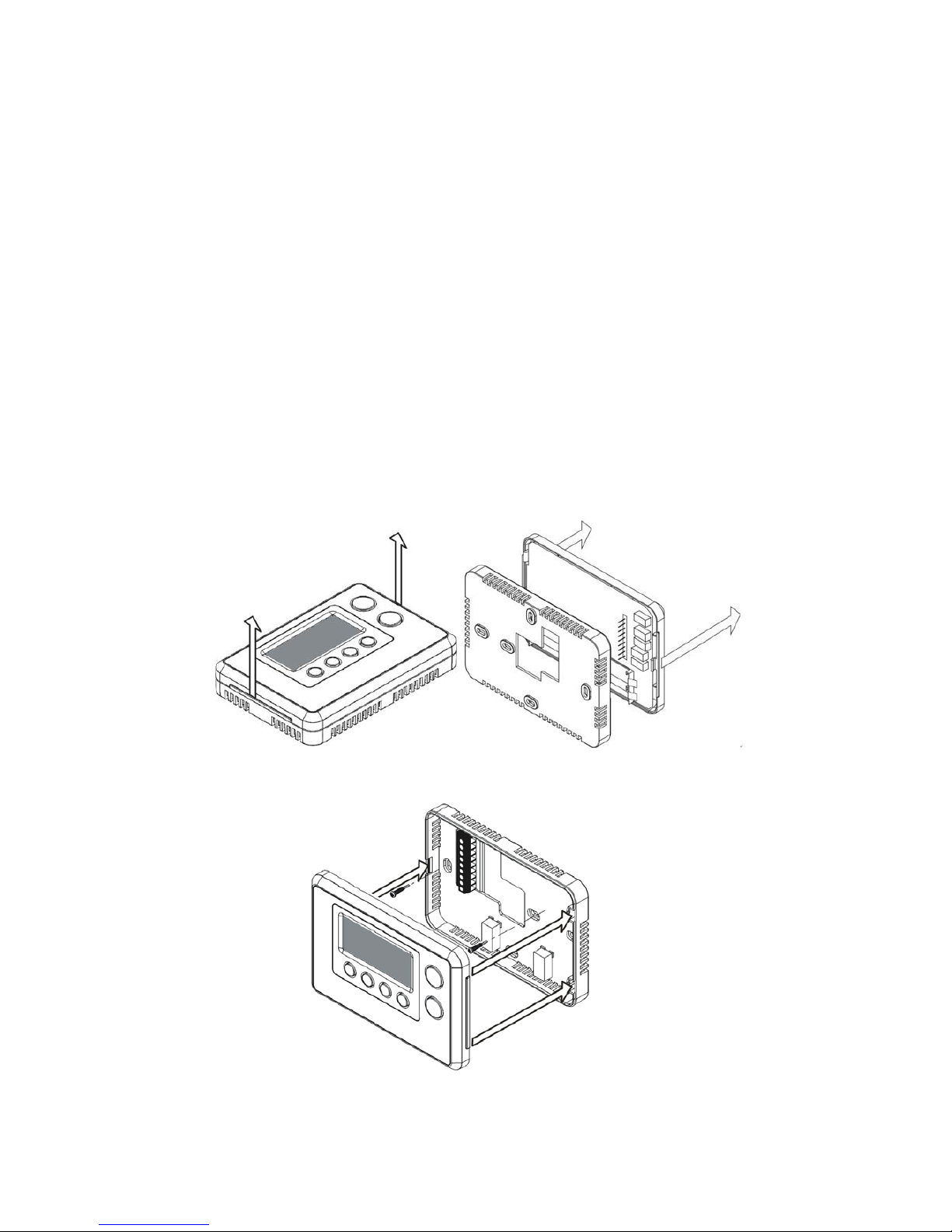
Physical Installation and Wiring .............................................6
Installation Location ............................................................7
Physically Installing the Thermostat ......................................7
Wiring ...............................................................................8
Jumper Settings for ELECTH-HPUMP and HE-HG ......................10
Setup and Operations .............................................................11
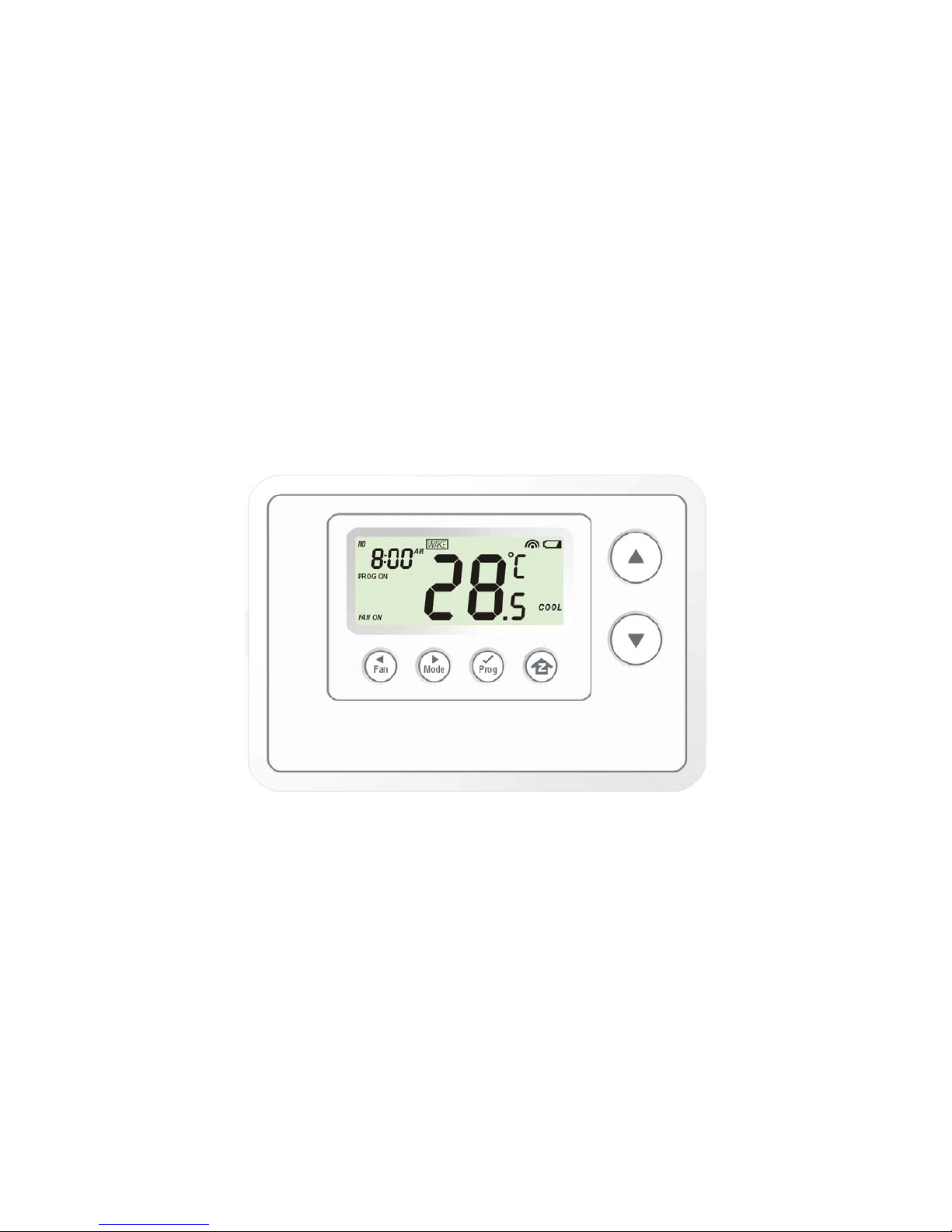
Product Overview ..............................................................11
Description of Function Keys .................................................11
Activate/Deactivate Easy Mode ............................................12
Temperature Scale selection in Easy Mode ..............................12
Setting Mode ......................................................................13
Change Mode .....................................................................18
Change Fan Mode ...............................................................19
Select Program Mode ..........................................................19
Override/Permanent Override ...............................................20
Setting Schedule ................................................................21
Battery Low Indication .........................................................24
Defrost Indication ...............................................................24
Out of Temperature Range Indication ....................................24
Advanced Recovery Indication ..............................................25
Filter Counter .....................................................................26
Short Cycle Start Up Protection .............................................27
Energy Saving Mode.............................................................27
Z-Wave Setup and Operations ................................................27
Z-Wave Add (Include) / Delete (Exclude) Mode .......................28
Support for Association Groups .............................................30
Z-Wave Configuration Parameters .........................................32
Reset ZTS-110 to Factory Default Settings .............................35
Frequently Asked Questions ...................................................36
Technical Specifications .........................................................37
Checking Accessories ............................................................38
FCC Notice ..............................................................................38
Warnings ................................................................................38
Caution ...................................................................................38
Warranty ................................................................................39

3
ZTS-110 Z-Thermostat
Introduction
ZTS‐110Z‐Thermostat(Figure1)isaZ‐Waveenabledprogrammablethermostatthatallowsyouto
controlyourroomtemperaturewithprogrammabletimeschedulesuchasWAKE,AWAY,HOMEand
SLEEPeventwhichcanmaximizeenergyconservationandcomfortwhileminimizingtheeffort
requiredtomaintainingtheappropriatetemperatureinyourhomewhetheryouareathomeor
away.
Also,youcanusetheZTS‐110tocontrol/checkyourroomtemperaturebysmartphoneorPC
whileyouareathomeoroutsidethroughZ‐Wavegateway.
Figure1.ZTS‐110

4
FeaturesList
HVACSystemTypeCompatible:
zStandard(gas/electric)orHeatPump
MultistageSystemCompatible:
zStandardHVACSystems:2stagesheating,1stagecooling
zHeatPumpSystems:2stagesheating,1stagecooling
HeatPumpchangeovervalve:
zSelectablechangeoverwithcoolorwithheat
ProgramStyle:
z2programmodesforscheduling(Mo‐Fr,Sa‐Su)
z4SeparateTimeandTemperatu reSettingsforeachprogram
zHeatandCoolset‐pointsforeachprogram
zTemp oraryProgramOverride
zPermanentProgramOverride
zBuilt‐inflashmemorystoresheatandcoolprogramsettings
TemperatureDisplayandControl:
zTemp eraturedisplayin°For°C
zTemp eratureMeasurableRange:32–99°F/0–40°C
zTemp eratureSettingRange:41‐99°F/5‐37°C
zAdjustableTem pe ratureControlSwing/Differential
a) Swing:1°F,2°F,3°For4°F(0.5°C,1.0°C,1.5°Cor2°C)
b) Differential:1°F,2°F,3°For4°F(0.5°C,1.0°C,1.5°Cor2°C)
zAdvancedRecoveryMode(ARM)
zDefrostFunction
zShortcyclestartupprotection
Clock:
zTimedisplayformat:12/24hourclockselectionwithdaydisplayed
FilterCounter:
zFilterchangereminderdisplayedafter500hoursusage(500‐4000hrs)
Z‐Wave:
zSupportNetworkWideInclusion(NWI)andExploreFrames
zSupportEasymode(disablelocaladvancedsetupandcontrol)
zSupport“FrequentlyListeningRoutingSlaves”(FLiRS)modeand“AlwaysListening”
mode
zSupportbatterylevelreport
zSupportAssociationGroups
a) AssociationGroup_1isusedforHeatPumpcontrol
b) AssociationGroup_2isusedforCompressorcontrol
c) AssociationGroup_3isusedtoreportstatuschangesuchasAUTOreportto
gateway
Power:
zSupportAAx4alkalinebatteriesor24Vacinput

5
Glossary
DeviceorNode
DevicesandnodesarealltermstodescribeanindividualZ‐Wave
device.TheseareallinterchangeablewhensettingupyourZ‐Wave
network.
InclusionAddaZ‐Wavedevicetothenetwork.
ExclusionDeleteaZ‐Wavedevicefromthenetwork.
RemoveTotakeadeviceoutofagroup,sceneorassociationgroupwhile
thatdevicestillexistsinthesameZ‐Wavenetwork.
NetworkWideInclusion
(NWI)
NetworkWideInclusion(NWI)enablesbothend‐userfriendly,Plug
andPlaylikeZ‐Wavenetworkinstallationaswellasprofessional
installationscenariowheretheinclusionprocessintermsoftime
willbereducedsignificantly.NWIisafeaturesupportedbyanew
frametypenamedExplorerwhichenablestheZ‐Waveprotocolto
implementAdaptiveSourceRouting.
Z‐WaveNetwork
AcollectionofZ‐Wavedevicesiscontrolledbyprimaryand
secondarycontrollersoperatingonthesamesystem.AZ‐Wave
networkhasitsownuniqueIDcodesothatcontrollersnotinthe
networkcannotcontrolthesystem.
PrimaryController
Thefirstcontrollerisusedtosetupyourdevicesandnetwork.
OnlythePrimaryControllercanbeusedtoincludeordelete
devicesfromanetwork.Itisrecommendedthatyoumarkthe
primarycontrollerforeachnetworkforeaseinmodifyingyour
network.
FLiRSMode
FLiRSisabbreviationfor“FrequentlyListeningRoutingSlave”.
FLiRSmodeistargetedforbatteryoperatedapplicationsandwill
entersleepmodefrequentlyinordertoconservebattery
consumption.TheresponsetoZ‐Wavecommandisnotasquickas
AlwaysListeningDevice.Normallythereis1‐2secondslatency.
AlwaysListeningMode
AlwaysListeningmodeistargetedforACpoweroperated
applicationsanditcanactasarepeater,whichwillre‐transmitthe
RFsignaltoensurethatthesignalisreceivedbyitsintended
destinationbyroutingthesignalaroundobstacleandradiodead
spots.TheresponsetoZ‐Wavecommandisimmediate.
Association
Associationisusedtoorganizenodesindifferentgroupsallowing
thedevicetoidentifythenodesbyagroupidentifier.Thegroups
canalsobecopiedtootherdevices.

6
PhysicalInstallationandWiring
LCAUTION
−WehighlyrecommendthatthisinstallationprocedureisperformedbyatrainedHVAC
technician.
−ReadtheenclosedinstructionscarefullybeforeinstallingyournewZ‐Thermostat.Payclose
attentiontoallwarningsandnotesandcarefullyfollowtheinstallationstepsintheorder
theyarepresentedtosavetimeandminimizetheriskofdamagingthethermostatorthe
systemitcontrols.
−TurnoffZTS‐110andtheelectronicdevices(e.g.heater,cooler)whichwillbeconnectedand
theelectricsourcebeforeinstallationandmaintenance.
Batterysafety!
−Usenewbatteriesoftherecommendedtypeandsizeonly.
−Nevermixusedandnewbatteriestogether.
−Toavoidchemicalleaks,removebatteriesfromtheZTS‐110ifyoudonotintendtousethe
unitforanextendedperiodoftime.
−Disposeofusedbatteriesproperly;donotburnorburythem.
ReadfollowingscenarioscarefullybeforeyoustartasitmatterstothebatterylifeunderZ‐Wave
operation:
ZTS‐110canbepoweredby4xAAbatteries,and/or24VacCwire.
a) Ifitispoweredbybatteriesorpoweredbybatteriesfirstthenappliedwith24Vacbefore
Z‐Waveinclusion,ZTS‐110willself‐configuretoFLiRSmodewhichwillsavebatterylifeby
sleeping.
b) Ifitispoweredby24Vacorpoweredby24VacfirstthenappliedwithbatteriesbeforeZ‐Wave
inclusion,ZTS‐110willself‐configuretoAlwaysListeningModewhichwillnotsleep.
c) Afterinclusionprocess,ZTS‐110willnotdetectpowersourceandnotallowchanging
operationmode.YoumustperformexclusionprocessfirstifneedtochangeZ‐Waveoperation
mode.
d) AfterZ‐Waveinclusionprocess,ifyouresetZTS‐110todefaultwhileboth24Vacandbatteries
areapplied,ZTS‐110willtake24Vacasprimarypowersourceandself‐configuretoAlways
ListeningMode,becauseresettodefaultprocesswillautomaticallyexcludeZTS‐110fromthe
Z‐Wavenetwork.Youshoulddisconnectthepowersourceandre‐applythepowersoZTS‐110
candetectthepowersourcetypeandself‐configuretocorrespondingmode.
YoumaycheckGlossaryforthedefinitionofFLiRSmodeandAlwaysListeningMode.

7
InstallationLocation:
TheThermostatisrestrictedtobeusedinindooronly.Itshouldbemountedonaninnerwallabout
1.5m(5ft)abovetheflooratapositionwhereitisreadilyaffectedbychangesofthegeneralroom
temperaturewithfreelycirculatingair.Avoidmountingaboveornearhotsurfacesorequipment
(e.g.TV,heater,refrigerator).Avoidmountingwhereitwillbeexposedtodirectsunshine,drafts,
orinalaundryroomorotherenclosedspace.Donotexposethisunittodrippingorsplashing
liquids.
PhysicallyInstallingtheThermostat:
1. OpentheZTS‐110bypullingthetwosectionsapart(Figure2).Usethefingertipsofonehandto
gripthetabonthefronthousing.
2. Applypowertothethermostat:
a) Forbatterypower,installfourAAbatteries(alkalinerecommended).Matchthepolarity
ofthebatterieswiththe+/‐marksinsidethebatterycompartment.
b) For24Vacpower,connectthewiresasdescribedin"Wiring"
3. Insertthetwoincludedwallanchorsintothewall,alignedwithtwoofthemountingholesin
thebackhousingofthethermostat.
4. Fastenthebackhousingtothewallusingthetwoincludedmountingscrews.Insertthescrews
throughthemountingholesinthehousingandintothewallanchors.(Figure3)
5. Alignthefronthousingofthethermostatwiththebackhousingandpushuntilthehousing
sectionsarelockedtogether.
Figure2.OpenZTS‐110
Figure3.Installthefronthousing

8
Wiring:
zBesuretheoperationmodeisOFFandFanselectionisFanAuto
zWirethepropercablesattheterminalblockaccordingtothecircuitdiagram
zAfterward,pushallcablesbackintothewall
zDonotusemetalconduitorofcableprovidedwithametalsheath
zRecommendsaddingfuseorprotectivedeviceinthelinecircuit
TerminalsSymbol
Coolchangeover(heatpump)O
Heatchangeover(heatpump)B
2ndStageheaterW2
1stStageheaterW1
FanG
CompressorY
24VacPowerforCooling RC
24VacPowerforHeating RH
24VacCommonC

9
Important!
IfyouwillbepoweringtheZTS‐110with24Vac:
Connectthe“24VacCommon”(typicallytheblackwire/terminal)and“24VacPower”(typically
theRedwire/terminal)fromtheHVACsystemtotheZTS‐110HVACSystemterminalblock“C”
and“RH”or“RC”terminals(seethefollowingexplanation,thesemaybejumperedtogether).
CommonorSplitTransformerSystems:
MostHVACsystemshaveacommonheatingandcoolingtransformer.Youmustinsertajumper
wiretotietheRHandRCinputstogetherforthisconfiguration.Ifyouhaveasystemwith
separateheatingandcoolingtransformers,donotinsertajumperwirebetweenRCandRH.
Whenwiringsplitsystems,wiretheheatingsystems“24VacPower”(redwire)totheZTS‐110
“RH”terminal,andwirethecoolingsystems“24VacPower”totheZTS‐110“RC”terminal.Also
wirethecoolingsystems“24VacCommon”totheZTS‐110“C”terminals.
Note:DonotsplitRC/RHforHeatPumpsystems!
Figure4.Non‐heatpump(StandardGasorElectric)HVACsystemwiring
Figure5.Heatpumpsystemwiring
O
B
W2
W1
G
Y
RC
RH
C C - 24Vac Common
R - 24Vac Power
Y - Compressor
G - Fan
W1 – 1st stage heater
W2 – 2nd stage heater
Black
Red
Yellow
Green
White
Brown
Standard HVAC System
O
B
W2
W1
G
Y
RC
RH
C C - 24Vac Common
R - 24Vac Power
Y - Compressor
G - Fan
W2 – 2nd stage heater
Black
Red
Yellow
Green
Brown
O - Cool changeover (heat pump)
Heat Pump HVAC System
ZTS-110
B - Heat changeover (heat pump)
Blue
Orange
ZTS-110

10
JumperSettingsforELECTH‐HPUMPandHE‐HG:
Thereare6jumperedpinsonthethermostatcircuitboardthatidentifywhetheryoursystemis:
‐ Gasorelectricheater
‐ Non‐heatpumporheatpumpsystem.
Youmustensurethatthesepinsaresetcorrectlyforyoursystem.Thepinlocationisshownin
thefollowingdiagramwhichislocatedatbacksideofZTS‐110.
JumperFunctionDescription
SettoELECTHfornon‐heatpumpsystem(Default).
‐Whenthereisaheatingrequest,thermostatwillturnonW1
‐Whenthereisacoolingrequest,thermostatwillturnonY
SettoHPUMPforheatpumpsystem.
‐Whenthereisaheatingrequest,thermostatwillturnonYandB
‐Whenthereisacoolingrequest,thermostatwillturnonYandO
SettoHGforGasheat‐fancontrolledunit(Default),
Fanwillmaintainoffstate.
SettoHEforElectricalheat‐fancontrolledunit,
Fanwillbeturnedonwhenthereisheatingoutput.
Note:
TheHEandHGjumpercontrolstheFanwhensettoAutoinheatingmode.
IfuserselectsFanONatthermostat,theFanwillbeturnedonwithoutconsideringtheHE‐HG
jumperselection.

11
SetupandOperations
ProductOverview
Figure6.ZTS‐110
DescriptionofFunctionKeys
SymbolKeyDescription
Increasevalue/To ggleselection
Decreasevalue/To ggleselection
Selectfanmode;alsotheBackwardfunctionkeyinsomemenus
Changeoperationmode;alsotheForwardfunctionkeyinsomemenus
Selectprogrammode:
PROGON,OVERRIDEandPERMANENTOVERRIDE;
alsotheConfirmfunctionkeyinsomemenus
BacktoHome
Batterylowindication
Mode
Programmode
Fanmode
Time
Day
Inclusionindication
Eventmode
Currenttemperature

12
Activate/DeactivateEasyMode
TheZTS‐110isdefaultwithEasymode,belowillustratesthefunctionsofEasymode:
•Activefunctions: ChangeMode,changeFanmodeandTem p eratureScaleselection
•Inactivefunctions:Scheduling,ProgramMode,ClockDisplay,SettingTime,SettingSwing,Setting,
DifferentialSet‐PointandAdvancedRecoveryMode
UsercanuseEasymodetodisableSchedulefunctionandtheschedulewillbecontrolledbyZ‐Wave
gateway.Usercanstillchangetemperatureandmodebypressingthelocalphysicalbuttons.
UsercandeactivatetheEasymodebylocal“SettingMode”orZ‐WaveConfigurationParameternumber
8.(PleaserefertoZ‐WaveConfigurationparameterstable).
Belowistheexamplebylocalsetting:
StepProcedure/DescriptionLCDindication
1
Pressandhold“Mode”keyfor2
secondstoentrythesettingmode.
Itwilldisplay“EASYYES”ifitstays
inEasymode.Otherwise,
itwilldisplay“EASYno”ifEasy
modeisdeactivated.
PressUp/Downkeytotogglethe
selection.
Press“Prog"keytoconfirm
yoursettings.
‐ItwillgobacktoHomepageif
selected“YES”.
‐itwillgotoDaysettingifselected
“no".
TemperatureScaleselectioninEasyMode
StepProcedure/DescriptionLCDindication
1
Pressandhold“Prog"keysfor
2secondstoentrytemperatureF
(Fahrenheit)‐>C(Celsius)selection
mode.
PressUp/Downkeytotogglethe
temperatureF(Fahrenheit)‐>
C(Celsius)selection.
⇓

13
Press“Prog"keytoconfirmit
andbacktotheHomepage.
Note:
IfyoudeactivatedtheEasymode,pleaserefertoSettingModeforthetemperaturescale
selection.
SettingMode(setDay,Clock,12/24hour,F/C,SwingandDifferential)
SymbolSettingModeKeyDescription
Increasevalue/To ggleselection
Decreasevalue/To ggleselection
Backwardtoprevioussetting
Forwardtonextsetting
Confirmandgotonextsetting
ConfirmandgobacktoHome
IfyoudeactivatedtheEasymode,youcancontinuetosetupDay,Clock,12/24hour,F/C,Swingand
Differential.Refertobelowforsteps:
StepProcedure/DescriptionLCDindication
1
Pressandhold“Mode”keyfor2
secondstoentrythesettingmode.
Itwilldisplay“EASYYES”ifitstays
inEASYmode.Otherwise,
itwilldisplay“EASYno”ifEASY
modeisdeactivated.
PressUp/Downkeytotogglethe

14
selection.
Press“Prog"keytoconfirm
yoursettings.
‐itwillgobacktoHomepageif
selected“YES”.
‐itwillgotoDaysettingifselected
“no".
EASYmode(default)
Localcontrolactivefunctions:
•ChangeMode
•ChangeFanmode
•Temperat ure Scaleselection
Localcontrolinactivefunctions:
•Scheduling
•ProgramMode
•ClockDisplay
•SettingTime
•SettingSwing
•SettingDifferentialSet‐Point
•AdvancedRecoveryMode
EASYmodeisdeactivated
•Supportfullfunctionsatlocal
andZ‐Wavecontrol
2
Daywillkeepflashing,press
Up/Downkeytosetdayfrom
MO‐SU.
3
Press“Prog"keyonceto
confirmthesettinganditwillgoto
hoursetting.
Hourwillkeepflashing,press
Up/Downkeytosethour.

15
4
Press“Prog"keyonceto
confirmthesettinganditwillgoto
minutessetting.
Minuteswillkeepflashing,press
Up/Downkeytosetminutes.
5
Press“Prog"keyonceto
confirmthesettinganditwillgoto
12/24hourclockselection.
PressUp/Downkeytotogglethe
12/24hourclockselection.
⇓
6
Press“Prog"keyonceto
confirmthesettinganditwillgoto
temperatureF(Fahrenheit)‐>
C(Celsius)selection.
PressUp/Downkeytotogglethe
temperatureF(Fahrenheit)‐>
C(Celsius)selection.
⇓
7
Press“Prog"keyonceto
confirmthesettinganditwillgoto
swingsetting.
PressUp/Downkeytosetthe

16
swingsetting.
(Rangeisfrom0.5oCto2oCor
1oFto4oF)
8
Press“Prog"keyonceto
confirmthesettinganditwillgoto
differentialsetpointsetting.
PressUp/Downkeytosetthe
differentialsetpointsetting.
(Rangeisfrom0.5oCto2oCor
1oFto4oF)
9
Press“Prog"keyonceto
confirmthesettinganditwillgoto
AdvancedRecoverysetting.
PressUp/Downkeyto
enable/disableAdvancedRecovery
Mode.
⇓
10
Press“Prog"keyonceto
confirmthesettinganditwillgoto
theHomepage.

17
Note:
ExplanationsofSwingandDifferentialsetpoint
HEATmode:thermostatcontrolsthetemperatureaccordingtothefollowingdiagram
ExampleforHeating:(Setpoint=70°F,Swing=1°F,Differential=2°F)
=>1ststageheaterturnsonwhenroomtempis69°Fandoffat71°F.
=>2ndstageheaterturnsonwhenroomtempis67°Fandoffat70°F.
COOLMode:thermostatcontrolsthetemperatureaccordingtothefollowingdiagram
ExampleforCooling:(Setpoint=80°F,Swing=1°F)
=>Coolerturnsonwhenroomtempis81°Fandoffat79°F.
AUTO:thermostatcontrolsthetemperatureaccordingtothefollowingdiagram
Output Set point
Temperature
Swing
1s
t
Turn off
1s
t
Turn on
Off
Heat
2n
d
Turn on 2n
d
Turn off
Diff SD= switch differential
Swing
Set point
Temperature
Turn off Turn on
Off
Cool
Swing
swingDead band
Output Heat Set point
Temperature
1s
t
Turn off
1s
t
Turn on
Off
Heat
2n
d
Turn on 2n
d
Turn off
Cool Set point
swing
Diff

18
Thereisadeadband4°F/2°Cbetweenheatsetpointandcoolsetpoint.
Example1:Ifuserselectheatsetpointis70F,theminimumcoolsetpointwillbelimited
at“heatsetpoint+4°F:74°F
Perviousheatsetpointis70°Fandcoolsetpointis74°F
Example2:Ifuserchangesheatsetpointto72F,coolsetpointwillbeupdatedto76°F
automaticallytomaintainthedeadband.
ChangeMode
Note:InHeatmode=>itdisplays“HEAT”ifELECTHisselectedduringjumpersetting.
=>itdisplays“HEATPUMP”ifHPUMPisselectedduringjumpersetting.
BelowexampleisbasedonHEATPUMP
StepProcedure/DescriptionLCDindication
1
Press“Mode”keyoncetochange
theoperationmode:
OFF‐>HEAT(PUMP)‐>COOL‐>
AUTO‐>OFF
⇓
⇓
⇓

19
ChangeFanMode
StepProcedure/DescriptionLCDindication
1
Press“Fan”keyoncetochangethe
Fanmode:
FANON‐>FANAUTO
FANAUTO:
Electricheat(HE):Fanrunsonly
whenHeating/Coolingisrunning.
Gasheat(HG):Fanrunsonlywhen
Coolingisrunning.
2
Press“Fan”keyoncetochangethe
Fanmode:
FANAUTO‐>FANON
FANON:
Fanstaysonallthetime.
SelectProgramMode:
StepProcedure/DescriptionLCDindication
1
Press“Prog”keyoncetoselect
PROGmode:
PROGON‐>OVERRIDE
‐>PERMANENTOVERRIDE
PROGON:Runtheschedule.
2
Press“Prog”keyoncetoselect
PROGmode:
OVERRIDE:Temporar yoverridethe
currentscheduleandwillgoback
to“PROGON”whennexttime
schedulereach.

20
3
Press“Prog”keyoncetoselect
PROGmode:
PERMANENTOVERRIDE:
Permanentoverridetheschedule
untiluserchangebackto“PROG
ON”.
Override/PermanentOverride
Note:Override/PermanentOverrideisonlyavailableinHEAT,COOLorAUTOmode.
StepProcedure/DescriptionLCDindication
1
Press“Prog”keyoncetoselect
PROGmode:OVERRIDEor
PERMANENTOVERRIDEatHome
page.
2
PressUp/Downkeytoadjustset
pointtemperatureinHEATorCOOL
mode.
Press“Prog”keyoncetoconfirm
thesetting.
or
3
InAUTOmode,userneedstoset
heatandcoolsetpoints
temperature.
PressUp/Downkeytoadjustauto
heatsetpointtemperaturein
AUTOHEATmode.
Other manuals for ZTS-110 Z-Thermostat
1
Table of contents
Other Remotec Thermostat manuals
Popular Thermostat manuals by other brands

Vaillant
Vaillant VSMART Installation and maintenance instructions

Braeburn
Braeburn 4030 user manual

Regulus
Regulus Caleon Installation and operation manual

ICM Controls
ICM Controls SC2201 Installation, operation & application guide

Imit
Imit TECHNO DPT user manual

Lux Products
Lux Products PSD011Ba Installation and operating instructions