REMS Picus S1 User manual

03/08 180605R
Maschinen und Werkzeuge für die Rohrbearbeitung
deu Elektrische Diamant-
Kernbohrmaschine
Betriebsanleitung
Vor Inbetriebnahme lesen!
eng Electric diamond
core drilling machine
Operating Instructions
Read before proceeding to initial startup!
fra Carotteuse électrique
avec couronnes diamantées
Instructions d’emploi
A lire avant la mise en service!
ita Carotatrice elettrica
diamantata
Istruzioni d’uso
Leggere prima della messa in servizio!
spa Perforadora eléctrica
con diamante
Manual de instrucciones
¡Leer antes de la puesta en marcha!
nld Elektrische diamant-
kernboormachine
Gebruiksaanwijzing
Voor ingebruikname lezen!
swe Elektrisk diamant-
kärnborrmaskin
Bruksanvisning
Läs noga igenom före användning!
nor Elektrisk diamant-
kjernebormaskin
Bruksanvisning
Må leses før idriftsettelse!
dan Elektrisk diamant-
kerneboremaskine
Betjeningsvejledning
Læses før ibrugtagning!
fin Sähkökäyttöinen
timanttiporakone
Käyttöohje
Lue ennen käyttöönottoa!
por Máquina eléctrica de furar
com coroa de diamantes
Manual de instruções
Leia antes da colocação em serviço!
pol Elektryczna wiertnica
diamentowa
Instrukcja obsługi
Przeczytać przed użyciem!
ces Elektrický diamantový
jádrový vrtací stroj
Návod k použití
Čtěte před uvedením do provozu!
slk Elektrický diamantový
jadrový vŕtací stroj
Návod na použitie
Prečítajte pred uvedením do prevádzky!
hun Elektromos
gyémánt-magfúrógép
Üzemeltetési leírás
Használat előtt olvassa el!
hrv/
Električna dijamantna bušilica
scg
za bušenje uz vađenje jezgre
Upute za uporabu
Pročitati prije uporabe bušilice!
slv Električni diamantni
vrtalni stroj
Navodila za uporabo
Preberite pred zagonom!
ron Carotieră electrică cu
segmente de diamant
Instrucţiuni de folosire
Se vor citi înainte de punerea în folosinţă!
rus
Электрический инструмент
для кольцевого сверления
с алмазными коронками
Инструкция по эксплуатации
Ознакомиться перед вводом в эксплуатацию!
grc
Ηλεκτρικό μηχάνημα περιμετρικής
διάτρησης με αδαμαντοκεφαλή
Οδηγίες Χρήσης
Διαβάστε πριν τη χρήση!
tur
Elektrikli-Elmas donanýmlý-
Karotiyer tipi delme makinesi
Kullanma talimatý
Çalýþtýrmadan önce mutlaka okuyunuz!
bul Електрическа диамантена
ядкова бормашина
Инструкция за експлоатация
Прочетете преди употреба!
lit Elektrinis deimantinis
græþtuvas
Naudojimo instrukcija
Prieð darbo pradþià bûtina perskaityti!
lav Elektriskâ urbjmaðîna
dimanta gredzenurbjiem
Ekspluatâcijas instrukcija
Pirms iekârtas lietoðanas jâizlasa!
est Elektriline Teemant-
puurmasin
Kasutusjuhend
Enne kasutuselevõttu läbi lugeda!
REMS-WERK
Maschinen- und Werkzeugfabrik
Postfach1631 · D-71306 Waiblingen
Tel. +49 7151 1707-0
Fax +49 7151 1707-110
www.rems.de
1
1
2
3
2
3

4
2
3
9
1
10
8
1214 13212019 11
16
17
18
5
5
6
Fig. 1 REMS Picus S1 und REMS Simplex
38
43
22
50
54
55
56 23
24
25
26
27
28
41
42
44
45
44
45
Fig. 2 REMS Picus S3 und REMS Duplex
15
15
Fig. 7 Leistungsschild
REMS Picus S3
7
37
7
2
36
33
5
5
4
40
1
30
29
6
10
8
1239 11
17
18
14 1321
20
19
16

Fig. 8 Leistungsschild
REMS Picus S2/3,5
4
5
6
40
1
2
21 11
39
5
37
7
29
30
33
36
53
15
43
42
41
52
Fig. 3 REMS Picus S2/3,5 und REMS Duplex 300
19
18
17
16

Fig. 4 Handgeführtes Trockenbohren mit Anbohrhilfe
Fig. 5 Dübelbefestigung des Bohrständers in Beton mit Einschlaganker
Fig. 6 Dübelbefestigung des Bohrständers in Mauerwerk
mit Spreizanker (Ankerschalen)
11 46 47 48 49
51
1
45
2
1
34
2
3

Allgemeine Sicherheitshinweise
ACHTUNG! Sämtliche Anweisungen sind zu lesen. Fehler bei der Einhal-
tungdernachstehendaufgeführtenAnweisungenkönnenelektrischenSchlag,
Brand und/oder schwere Verletzungen verursachen. Der nachfolgend ver-
wendete Begriff „elektrisches Gerät“ bezieht sich auf netzbetriebene Elek-
trowerkzeuge (mit Netzkabel), auf akkubetriebene Elektrowerkzeuge (ohne
Netzkabel), auf Maschinen und auf elektrische Geräte. Verwenden Sie das
elektrische Gerät nur bestimmungsgemäß und unter Beachtung der allge-
meinen Sicherheits- und Unfallverhütungsvorschriften.
BEWAHREN SIE DIESE ANWEISUNGEN GUT AUF.
A) Arbeitsplatz
a) Halten Sie Ihren Arbeitsbereich sauber und aufgeräumt. Unordnung
und unbeleuchtete Arbeitsbereiche können zu Unfällen führen.
b) Arbeiten Sie mit dem elektrischen Gerät nicht in explosionsgefähr-
deter Umgebung, in der sich brennbare Flüssigkeiten, Gase oder
Stäube befinden. Elektrische Geräte erzeugen Funken, die den Staub
oder die Dämpfe entzünden können.
c) Halten Sie Kinder und andere Personen während der Benutzung des
elektrischen Gerätes fern. Bei Ablenkung können Sie die Kontrolle über
das Gerät verlieren.
B) Elektrische Sicherheit
a) Der Anschlussstecker des elektrischen Gerätes muss in die Steck-
dose passen. Der Stecker darf in keiner Weise verändert werden.
Verwenden Sie keine Adapterstecker gemeinsam mit schutzgeer-
detenelektrischenGeräten.UnveränderteSteckerundpassendeSteck-
dosen verringern das Risiko eines elektrischen Schlages. Ist das elektri-
sche Gerät mit Schutzleiter ausgerüstet, darf es nur an Steckdosen mit
Schutzkontaktangeschlossenwerden.BetreibenSiedaselektrischeGerät
auf Baustellen, in feuchter Umgebung, im Freien oder bei vergleichbaren
Aufstellartennurübereinen30mA-Fehlerstrom-Schutzschalter(FI-Schalter)
am Netz.
b) Vermeiden Sie Körperkontakt mit geerdeten Oberflächen, wie von
Rohren, Heizungen, Herden und Kühlschränken. Es besteht ein er-
höhtes Risiko durch elektrischen Schlag, wenn Ihr Körper geerdet ist.
c) Halten Sie das Gerät von Regen oder Nässe fern. Das Eindringen von
Wasser in ein Elektrogerät erhöht das Risiko eines elektrischen Schlages.
d) Zweckentfremden Sie das Kabel nicht, um das Gerät zu tragen,
aufzuhängen oder um den Stecker aus der Steckdose zu ziehen.
Halten Sie das Kabel fern von Hitze, Öl, scharfen Kanten oder sich
bewegendenGeräteteilen.Beschädigte oderverwickelte Kabel erhöhen
das Risiko eines elektrischen Schlages.
e) Wenn Sie mit einem elektrischen Gerät im Freien arbeiten, verwen-
den Sie nur Verlängerungskabel, die auch für den Außenbereich zu-
gelassen sind. Die Anwendung eines für den Außenbereich geeigneten
Verlängerungskabels verringert das Risiko eines elektrischen Schlages.
C) Sicherheit von Personen
a) Seien Sie aufmerksam, achten Sie darauf, was Sie tun, und gehen
Sie mit Vernunft an die Arbeit mit einem elektrischen Gerät. Benut-
zen Sie das elektrische Gerät nicht, wenn Sie müde sind oder unter
dem Einfluss von Drogen, Alkohol oder Medikamenten stehen. Ein
Moment der Unachtsamkeit beim Gebrauch des Gerätes kann zu ernst-
haften Verletzungen führen.
b) Tragen Sie persönliche Schutzausrüstung und immer eine Schutz-
brille. Das Tragen persönlicher Schutzausrüstung, wie Staubmaske,
rutschfeste Sicherheitsschuhe, Schutzhelm oder Gehörschutz, je nach
Art und Einsatz des elektrischen Gerätes, verringert das Risiko von Ver-
letzungen.
c) Vermeiden Sie eine unbeabsichtigte Inbetriebnahme. Vergewissern
Sie sich, dass der Schalter in der Position „AUS“ ist, bevor Sie den
Stecker in die Steckdose stecken. Wenn Sie beim Tragen des elektri-
schen Gerätes den Finger am Schalter haben oder das Gerät einge-
schaltet an die Stromversorgung anschließen, kann dies zu Unfällen
führen. Überbrücken Sie niemals den Tippschalter.
d) Entfernen Sie Einstellwerkzeuge oder Schraubenschlüssel, bevor
Sie das elektrische Gerät einschalten. Ein Werkzeug oder Schlüssel,
der sich in einem drehenden Geräteteil befindet, kann zu Verletzungen
führen. Greifen Sie niemals in sich bewegende (umlaufende) Teile.
e) Überschätzen Sie sich nicht. Sorgen Sie für einen sicheren Stand
und halten Sie jederzeit das Gleichgewicht. Dadurch können Sie das
Gerät in unerwarteten Situationen besser kontrollieren.
f) TragenSie geeigneteKleidung. TragenSie keine weite Kleidung oder
Schmuck. Halten Sie Haare, Kleidung und Handschuhe fern von sich
bewegenden Teilen. Lockere Kleidung, Schmuck oder lange Haare kön-
nen von sich bewegenden Teilen erfasst werden.
g) Wenn Staubabsaug- und -auffangeinrichtungen montiert werden
können, vergewissern Sie sich, dass diese angeschlossen sind und
richtig verwendet werden. Das Verwenden dieser Einrichtungen ver-
ringert Gefährdungen durch Staub.
h) Überlassen Sie das elektrische Gerät nur unterwiesenen Personen.
Jugendliche dürfen das elektrische Gerät nur betreiben, wenn sie über
16 Jahre alt sind, dies zur Erreichung ihres Ausbildungszieles erforder-
lich ist und sie unter Aufsicht eines Fachkundigen gestellt sind.
D) Sorgfältiger Umgang und Gebrauch von elektrischen Geräten
a) Überlasten Sie das elektrische Gerät nicht. Verwenden Sie für Ihre
Arbeit das dafür bestimmte elektrische Gerät. Mit dem passenden
elektrischen Gerät arbeiten Sie besser und sicherer im angegebenen Lei-
stungsbereich.
b) Benutzen Sie kein elektrisches Gerät, dessen Schalter defekt ist. Ein
elektrisches Gerät, das sich nicht mehr ein- oder ausschalten lässt, ist
gefährlich und muss repariert werden.
c) Ziehen Sie den Stecker aus der Steckdose, bevor Sie Geräte-
einstellungen vornehmen, Zubehörteile wechseln oder das Gerät
weglegen. Diese Vorsichtsmaßnahme verhindert den unbeabsichtigten
Start des Geräts.
d) Bewahren Sie unbenutzte elektrische Geräte außerhalb der Reich-
weite von Kindern auf. Lassen Sie Personen das elektrische Gerät
nicht benutzen, die mit diesem nicht vertraut sind oder diese An-
weisungen nicht gelesen haben. Elektrische Geräte sind gefährlich,
wenn sie von unerfahrenen Personen benutzt werden.
e) Pflegen Sie das elektrische Gerät mit Sorgfalt. Kontrollieren Sie, ob
bewegliche Geräteteile einwandfrei funktionieren und nicht klem-
men, ob Teile gebrochen oder so beschädigt sind, dass die Funk-
tion des elektrischen Gerätes beeinträchtigt ist. Lassen Sie be-
schädigte Teile vor dem Einsatz des elektrischen Gerätes von qua-
lifiziertem Fachpersonal oder von einer autorisierten REMS
Vertrags-Kundendienstwerkstatt reparieren. Viele Unfälle haben ihre
Ursache in schlecht gewarteten Elektrowerkzeugen.
f) Halten Sie Schneidwerkzeuge scharf und sauber. Sorgfältig gepflegte
Schneidwerkzeuge mit scharfen Schneidkanten verklemmen sich weni-
ger und sind leichter zu führen.
g) Sichern Sie das Werkstück. Benutzen Sie Spannvorrichtungen oder
einen Schraubstock, um das Werkstück festzuhalten. Es ist damit siche-
deu deu
Fig. 1–7
1 Bohrsäule
2 Vorschubschlitten
3 Geschlitzte Hülse
4 Vorschubhebel
5 Stellschrauben
6 Grundplatte
7 Schlitz
8 Zylinderschraube
9 Drehgriff
10 Spannwinkel
11 Antriebsspindel
12 Gegenhalter
13 Spannhals
14 Deckel
15 Wasserzuführeinrichtung
16 Schutzschalter PRCD Kontrollleuchte
17 Schutzschalter PRCD Taste RESET
18 Schutzschalter PRCD Taste TEST
19 Fehlerstrom-Schutzschalter PRCD
20 Motorgriff
21 Schalter
22 Adapter
23 Einschlaganker
24 Setzeisen
25 Kordelgewindestange
26 Scheibe
27 Schnellspannmutter
28 Spreizanker
29 Spannkopf
30 Kontermutter
33 Gewindespindel
36 Schieberiegel
37 Schrauben
38 Distanzstück
39 Schaltgriff
40 Streben
41 Schlauchanschluss
42 Abdeckplatte
43 Dichtring
44 Wasserabsaug-
vorrichtung
45 Gummischeibe
46 Saugrotor
47 Bohrkronenanschluss
UNC 1
1
/
4
und G
1
/
2
48 Diamant-Kernbohrkrone
49 Anbohrhilfe
50 Bohrkronen-
Verlängerung
51 Druckwasserbehälter
52 Schrauben
53 Führung
54 Leichtlösering
55 Schärfstein
56 Nivellierblock

rer gehalten als mit Ihrer Hand, und Sie haben außerdem beide Hände
zur Bedienung des elektrischen Gerätes frei.
h) Verwenden Sie elektrische Geräte, Zubehör, Einsatzwerkzeuge usw.
entsprechend diesen Anweisungen und so, wie es für diesen spe-
ziellen Gerätetyp vorgeschrieben ist. Berücksichtigen Sie dabei die
Arbeitsbedingungen und die auszuführende Tätigkeit. Der Gebrauch
von elektrischen Geräten für andere als die vorgesehenen Anwendun-
gen kann zu gefährlichen Situationen führen. Jegliche eingenmächtige
Veränderung am elektrischen Gerät ist aus Sicherheitsgründen nicht ge-
stattet.
E) Sorgfältiger Umgang und Gebrauch von Akkugeräten
a) Stellen Sie sicher, dass das elektrische Gerät ausgeschaltet ist, be-
vor Sie den Akku einsetzen. Das Einsetzen eines Akkus in ein elektri-
sches Gerät, das eingeschaltet ist, kann zu Unfällen führen.
b) Laden Sie die Akkus nur in Ladegeräten auf, die vom Hersteller emp-
fohlen werden. Für ein Ladegerät, das für eine bestimmte Art von Akkus
geeignet ist, besteht Brandgefahr, wenn es mit anderen Akkus verwendet
wird.
c) Verwenden Sie nur die dafür vorgesehenen Akkus in den elektrischen
Geräten. Der Gebrauch von anderen Akkus kann zu Verletzungen und
Brandgefahr führen.
d) Halten Sie den nicht benutzten Akku fern von Büroklammern, Mün-
zen, Schlüsseln, Nägeln, Schrauben oder anderen kleinen Metallge-
genständen, die eine Überbrückung der Kontakte verursachen könn-
ten. Ein Kurzschluss zwischen den Akkukontakten kann Verbrennungen
oder Feuer zur Folge haben.
e) Bei falscher Anwendung kann Flüssigkeit aus dem Akku austreten.
Vermeiden Sie den Kontakt damit. Bei zufälligem Kontakt mit Wasser
abspülen. Wenn die Flüssigkeit in die Augen kommt, nehmen Sie zu-
sätzlich ärztliche Hilfe in Anspruch. Austretende Akkuflüssigkeit kann zu
Hautreizungen oder Verbrennungen führen.
f) Bei Temperaturen des Akku/Ladegerätes oder Umgebungstempera-
turen 5°C/40°F oder b40°C/105°F darf der Akku/das Ladegerät nicht
benutzt werden.
g) Entsorgen Sie schadhafte Akkus nicht im normalen Hausmüll, son-
dern übergeben Sie sie einer autorisierten REMS Vertrags-Kunden-
dienstwerkstatt oder einem anerkannten Entsorgungsunternehmen.
F) Service
a) Lassen Sie das elektrische Gerät nur von qualifiziertem Fachperso-
nal und nur mit Original Ersatzteilen reparieren. Damit wird sicherge-
stellt, dass die Sicherheit des elektrischen Gerätes erhalten bleibt.
b) Befolgen Sie Wartungsvorschriften und die Hinweise über den Werk-
zeugwechsel.
c) Kontrollieren Sie regelmäßig die Anschlussleitung des elektrischen
Gerätes und lassen Sie sie bei Beschädigung von qualifiziertem Fach-
personal oder von einer autorisierten REMS Vertrags-Kundendienst-
werkstatt erneuern. Kontrollieren Sie Verlängerungskabel regelmäßig
und ersetzen Sie sie, wenn sie beschädigt sind.
Spezielle Sicherheitshinweise
•
Nur Steckdosen mit Schutzkontakt verwenden. Schutzerdung der Steck-
dose überprüfen.
•
Nur Verlängerungskabel mit Schutzkontakt verwenden.
•
Antriebsmaschine niemals ohne den mitgelieferten Fehlerstrom-Schutz-
schalter PRCD verwenden.
•
Jeweils vor Bohrbeginn die Funktion des Fehlerstrom-Schutzschalter
PRCD prüfen (siehe 3.).
•
Antriebsmaschine beim Bohren nur an den dafür vorgesehenen, isolier-
ten Griffen führen.
•
Darauf achten, dass beim Betrieb kein Wasser in den Motor der An-
triebsmaschine gelangt.
•
Bei Undichtigkeiten in Teilen der Wasserzuführungseinrichtung Betrieb
sofort einstellen und Undichtigkeit beheben. Wasserdruck von 4 bar nicht
überschreiten.
•
Kernbohrungen von Bauverantwortlichen anzeichnen lassen.
•
Die Baustatik darf durch die Kernbohrung nicht nachteilig beeinflusst
werden, gegebenenfalls Bauleitung oder Statiker hinzuziehen.
•
Gas-, Wasser-, Strom- oder sonstige Leitungen im Bohrbereich beach-
ten, gegebenenfalls entleeren/abschalten.
•
Arbeitsbereichabsperren,beiDurchgangsbohrungenbeidseitig,und/oder
durch Warnposten sichern.
•
Vorkehrungentreffen,dass ein eventuell herausfallender Bohrkern keinen
Personen- oder Sachschaden verursacht.
•
Bei hohlen Bauteilen prüfen, wohin das Bohrwasser fließt um Schäden
(z. B. Frostschäden) zu vermeiden.
•
Rechnen Sie immer damit, dass die Diamant-Kernbohrkrone blockieren
kann. Beim handgeführten Kernbohren besteht dann die Gefahr, dass Ih-
nen die Antriebsmaschine aus der Hand geschlagen wird.
•
Überkopfarbeiten sind mit elektrisch betriebenen Kernbohrmaschinen
nicht zulässig.
1. Technische Daten
1.1. Artikelnummern
REMS Picus S1 Antriebsmaschine 180000
REMS Picus S3 Antriebsmaschine 180001
REMS Picus S2/3,5 Antriebsmaschine 180002
Gegenhalter 180050
REMS Simplex Bohrständer 182000
REMS Duplex Bohrständer 182001
REMS Duplex 300 Bohrständer 182012
Universal-Diamant-Kernbohrkronen
REMS UDKB 32 x 420 x UNC 1
1
/
4
181010
REMS UDKB 42 x 420 x UNC 1
1
/
4
181015
REMS UDKB 52 x 420 x UNC 1
1
/
4
181020
REMS UDKB 62 x 420 x UNC 1
1
/
4
181025
REMS UDKB 72 x 420 x UNC 1
1
/
4
181030
REMS UDKB 82 x 420 x UNC 1
1
/
4
181035
REMS UDKB 92 x 420 x UNC 1
1
/
4
181040
REMS UDKB 102 x 420 x UNC 1
1
/
4
181045
REMS UDKB 112 x 420 x UNC 1
1
/
4
181050
REMS UDKB 125 x 420 x UNC 1
1
/
4
181057
REMS UDKB 132 x 420 x UNC 1
1
/
4
181060
REMS UDKB 152 x 420 x UNC 1
1
/
4
181065
REMS UDKB 162 x 420 x UNC 1
1
/
4
181070
REMS UDKB 182 x 420 x UNC 1
1
/
4
181075
REMS UDKB 200 x 420 x UNC 1
1
/
4
181080
REMS UDKB 225 x 420 x UNC 1
1
/
4
181085
REMS UDKB 250 x 420 x UNC 1
1
/
4
181090
REMS UDKB 300 x 420 x UNC 1
1
/
4
181095
Spreizanker M12 (Mauerwerk), 10 Stück 079006
Einschlaganker M12 (Beton), 50 Stück 079005
Setzeisen für Einschlaganker M12 182050
Schnellspann-Set (Art.-Nr. 079007, 079008, 079009) 079010
Kordelgewindestange M12 x 65 079008
Schnellspann-Mutter 079009
Scheibe 079007
Anbohrhilfe G ½ für Bohrer Ø 8 mm 180150
Einmaulschlüssel SW 19 079000
Einmaulschlüssel SW 30 079001
Einmaulschlüssel SW 32 079002
Einmaulschlüssel SW 41 079003
Sechskant-Stiftschlüssel SW 3 079011
Sechskant-Stiftschlüssel SW 6 079004
Saugrotor zur Staubabsaugung 180160
Adapter G ½ außen – UNC 1¼ außen 180052
Adapter UNC 1¼ außen – Hilti BI 180053
Adapter UNC 1¼ außen – Hilti BU 180054
Adapter UNC 1¼ außen – Würth 180055
Bohrkronen-Verlängerung 200 mm x UNC 1¼ 180155
Schärfstein 079012
Druckwasserbehälter 182006
Leichtlösering 180015
Nivellierblock 182009
Wasserabsaug-Vorrichtung Simplex 182002
Wasserabsaug-Vorrichtung Duplex 182003
1.2. Bohrtiefe
Nutzbare Bohrtiefe der REMS Universal-Diamant-
Kernbohrkronen 420 mm
Tiefere Kernbohrungen mit Bohrkronen-Verlängerung siehe 3.7.
deu deu

1.3. Bohrbereich Picus S1 Picus S3 Picus S2/3,5
Kernbohrungen
in Stahlbeton Ø 20–102 Ø 20–152 Ø 40–300 mm
(132) mm (200) mm
Kernbohrungen
in Mauerwerk Ø 20–152 mm Ø 20–252 mm Ø 40–300 mm
Bohrkronen-
Anschlussgewinde UNC 1¼ auß., UNC 1¼ auß., UNC 1¼
G ½ innen G ½ innen
Spannhals-Ø 60 mm 60 mm
1.4. Drehzahlen Picus S1 Picus S3 Picus S2/3,5
230 V, 50–60 Hz
Leerlauf 830 min-
1
750, 1800, 2500 min-
1
490, 1160 min-
1
Nennlast 580 min-
1
530, 1280, 1780 min-
1
320, 760 min-
1
115 V, 50–60 Hz
Leerlauf 940 min-
1
770, 1860, 2580 min-
1
440, 1030 min-
1
Nennlast 740 min-
1
570, 1380, 1920 min-
1
290, 680 min-
1
1.5. Elektrische Daten Picus S1 Picus S3 Picus S2/3,5
Netzspannung 230 V, 50/60 Hz
aufgenommene Leistung 1800 W 2200 W 3420 W
Nennstromaufnahme 8,4 A 10 A 16 A
Absicherung (Netz) 10 A (B) 16 A (B) 16 A (B)
Fehlerstrom-Schutzschalter
PRCD 10 mA 10 mA 10 mA
mit Unterspannungsauslösung
Netzspannung 115 V, 50/60 Hz
aufgenommene Leistung 1700 W 2050 W 2820 W
Nennstromaufnahme 15 A 18 A 25 A
Absicherung (Netz) 20 A 25 A 25 A
Fehlerstrom-Schutzschalter
PRCD 6 mA 6 mA 6 mA
mit Unterspannungsauslösung
1.6. Abmessungen (L x B x H)
REMS Picus S1
Antriebsmaschine 460×160×100 mm (18,1”×6,3”×3,9”)
REMS Picus S3
Antriebsmaschine 540×160×100 mm (21,3”×6,3”×3,9”)
REMS Picus S2/3,5
Antriebsmaschine 490×170×135 mm (19,3”×6,7”×5,3”)
REMS Simplex Bohrständer 400×200×775 mm (15,7”×7,9”×30,5”)
REMS Duplex Bohrständer 440×230×935 mm (17,3”×9,1”×36,8”)
REMS Duplex 300 Bohrst. 480×300×1060 mm (18,9”×11,8”×41,7”)
1.7. Gewichte
REMS Picus S1 Antriebsmaschine 5,2 kg (11,5 lb)
REMS Picus S3 Antriebsmaschine 7,4 kg (16,3 lb)
REMS Picus S2/3,5 Antriebsmaschine 13,6 kg (30,0 lb)
REMS Simplex Bohrständer 9,7 kg (21,4 lb)
REMS Duplex Bohrständer 12,8 kg (28,2 lb)
REMS Duplex 300 Bohrständer 16,2 kg (35,8 lb)
1.8. Lärminformation Picus S1 Picus S3 Picus S2/3,5
Arbeitsplatzbezogener
Emissionswert 90 dB (A) 90 dB (A) 91 dB (A)
Schallleistungspegel 103 dB (A) 103 dB (A) 104 dB (A)
1.9. Vibrationen
Gewichteter Effektivwert
der Beschleunigung 2,5 m/s
2
2,5 m/s
2
2,5 m/s
2
2. Inbetriebnahme
2.1. Elektrischer Anschluss
Vor Anschluss der Maschine prüfen, ob die auf dem Leistungsschild an-
gegebene Spannung der Netzspannung entspricht. Vor jeder Inbe-
triebnahme muss die Funktion des Fehlerstrom-Schutzschalters PRCD
(19) geprüft werden (siehe 3.).
2.2. Antriebsmaschinen REMS Picus S1, REMS Picus S3
und REMS Picus S2/3,5
Die Antriebsmaschinen REMS Picus S1, REMS Picus S3 und REMS
Picus S2/3,5 sind universell einsetzbar zum Trocken- oder Nassboh-
ren, handgeführt (Picus S1, Picus S3) oder mit Bohrständer. Der kom-
binierte Bohrkronenanschluss der Antriebsspindel (11) von REMS Pi-
cus S1 und REMS Picus S3 erlaubt sowohl die direkte Aufnahme von
Diamant-KernbohrkronenmitInnengewindeUNC1
1
/
4
alsauchmitAußen-
gewinde G
1
/
2
. Bei den Antriebsmaschinen Picus S1 und Picus S3 ist
im Anlieferungszustand die Wasserzuführeinrichtung (15) nicht mon-
tiert, sondern beigelegt. Die Aufnahme für den Wasseranschluss an den
Antriebsmaschinen ist mit einem Deckel (14) verschlossen. In diesem
Zustand sind die Antriebsmaschinen (REMS Picus S1, REMS Picus S3)
zum Trockenbohren einsetzbar. Bei REMS Picus S2/3,5 ist die Was-
serzuführeinrichtung bereits vormontiert. Nassbohren siehe 2.5.
Die Drehzahl der Antriebsmaschine für wirtschaftliches Kernbohren ist
vom Durchmesser der Diamant-Kernbohrkrone abhängig. Die Wahl der
Drehzahl der Antriebsmaschine sollte beim Bohren in Stahlbeton so er-
folgen, dass die Umfangsgeschwindigkeit (Schnittgeschwindigkeit) der
Diamant-Kernbohrkrone in einem Bereich zwischen 2 und 4 m/s liegt.
Außerhalb dieses optimalen Bereichs kann selbstverständlich ebenfalls
gebohrt werden, allerdings mit Zugeständnissen an die Arbeitsge-
schwindigkeit und/oder die Standzeit der Diamant-Kernbohrkronen. Für
Mauerwerk gelten höhere Umfangsgeschwindigkeiten.
Die Drehzahl von REMS Picus S1 ist fest eingestellt. Ab einem Bohr-
durchmesser von 62 mm arbeitet REMS Picus S1 in Stahlbeton im
optimalen Bereich der Umfangsgeschwindigkeit, bei kleineren Durch-
messern immer noch im akzeptablen Bereich. Die Diamant-Segmente
der REMS Universal-Diamant-Kernbohrkronen wurden in der Bindung
derart modifiziert, dass mit diesen auch bei kleineren Durchmessern mit
REMS Picus S1 gut gebohrt werden kann.
Die Drehzahl von REMS Picus S3 kann durch ein 3-stufiges Schalt-
getriebe so gewählt werden, dass in Stahlbeton immer im optimalen
Bereich gebohrt wird. Der richtige Gang kann dem Leistungsschild (Fig.
7) der REMS Picus S3 entnommen werden. Die dort abgebildete Tabelle
zeigt in der ersten Spalte die Gänge 1 bis 3, in der zweiten die dazu-
gehörigen Drehzahlen, in der dritten die Bohrkronendurchmesser für
Mauerwerk und in der vierten die Bohrkronendurchmesser für Stahl-
beton. Es wird also z. B. eine Kernbohrung Ø 102 mm in Mauerwerk im
3. Gang, in Stahlbeton im 1. Gang gebohrt.
Die Drehzahl von REMS Picus S2/3,5 kann durch ein 2-stufiges Schalt-
getriebe so gewählt werden, dass immer im optimalen Bereich gebohrt
wird. Der richtige Gang kann dem Leistungsschild (Fig. 8) der REMS
Picus S2/3,5 entnommen werden. Die dort abgebildete Tabelle zeigt in
der ersten Spalte die Gänge 1 und 2, in der zweiten die dazugehörigen
Drehzahlen, in der dritten die Bohrkronendurchmesser für Mauerwerk
und Stahlbeton.
Achtung: Getriebe nur im Stillstand schalten. Niemals im Lauf oder
während des Auslaufs schalten. Sollte sich ein Gang nicht schalten las-
sen, so ist gleichzeitig der Schaltgriff (39) zu drehen und die Antriebs-
spindel/Diamant-Kernbohrkrone von Hand zu bewegen. Vorher Netz-
stecker ziehen!
2.3. Universal-Diamant-Kernbohrkronen REMS UDKB
Die Schneideigenschaften der Diamant-Kernbohrkrone werden durch
die Diamantqualität, die Diamantkorngröße und -form sowie durch die
Bindung, dem Metallpulver in dem die Diamantkörner gebunden sind,
bestimmt. Anwender, die eine Vielzahl von Kernbohrungen durchzu-
führen haben, müssen zur optimalen Anpassung der Schneideigen-
schaften der Diamant-Kernbohrkrone an die unterschiedlichen Bohr-
aufgabeneineVielzahlverschiedenerDiamant-KernbohrkronenjeGröße
bereithalten. Häufig kann erst vor Ort ausprobiert werden, welche Dia-
mant-Kernbohrkrone im Hinblick auf Schneidleistung (Arbeitsge-
schwindigkeit) und Standzeit für eine Bohraufgabe optimal geeignet ist.
Oftmals ist sogar die Kontaktaufnahme des Anwenders zum Hersteller
der Diamant-Kernbohrkronen erforderlich, um optimal geeignete Dia-
mant-Kernbohrkronen bereitstellen zu können.
Für gängige Bohraufgaben hat REMS Universal-Diamant-Kernbohr-
kronen entwickelt. Diese sind universell einsetzbar zum Trocken- und
Nassbohren, handgeführt oder mit Bohrständer. Das Anschlussgewin-
de der REMS Universal-Diamant-Kernbohrkronen UNC 1
1
/
4
passt zu
deu deu

REMS Picus S1, REMS Picus S3 und REMS Picus S2/3,5 und zu ge-
eigneten Antriebsmaschinen anderer Fabrikate. Bei abweichendem An-
schlussgewinde der Antriebsmaschine sind Adapter als Zubehör (22)
lieferbar.
2.3.1. Montage der Diamant-Kernbohrkrone
Netzstecker ziehen. Gewählte Diamant-Kernbohrkrone auf die An-
triebsspindel (11) der Antriebsmaschine schrauben und von Hand mit
leichtemSchwungfestziehen.Esistvorteilhaft,zwischenDiamant-Kern-
bohrkrone und Antriebsspindel den Leichtlösering (Art.Nr.180015) ein-
zulegen. Anziehen mit Maulschlüssel ist nicht erforderlich. Darauf ach-
ten, dass die Gewinde der Antriebsspindel und der Diamant-Kernbohr-
krone sauber sind.
2.3.2. Demontage der Diamant-Kernbohrkrone
Netzstecker ziehen. Mit Maulschlüssel SW 32 die Antriebsspindel (11)
festhalten und mit Maulschlüssel SW 41 die Diamant-Kernbohrkrone
(48) lösen.
Nach Beendigung der Bohrarbeiten Diamant-Kernbohrkrone immer von
der Antriebsmaschine abschrauben. Insbesondere nach dem Nass-
bohren besteht sonst die Gefahr, dass sich die Diamant-Kernbohrkrone
wegen Korrosion nur noch schwer lösen lässt.
Achtung: Die Bohrrohre der Diamant-Kernbohrkronen sind nicht gehär-
tet. Schläge (mit Werkzeugen) und Stöße (Transport) auf das Bohrrohr
führen zu Beschädigungen, die zum Klemmen der Diamant-Kernbohr-
kronen und/oder des Bohrkerns führen. Die Diamant-Kernbohrkrone
kann dadurch unbrauchbar werden.
2.3.3. Schärfen der Diamant-Kernbohrkrone
REMSDiamant-KernbohrkronensindimAnlieferungszustandgeschärft.
BeirichtigemVorschubdruckschärfen sich die Diamant-Segmente selbst
nach. Ungeeigneter Vorschubdruck kann dazu führen, dass die Dia-
mant-Segmente „poliert“ werden und damit nicht mehr schneiden. In
diesem Fall wird mit der Diamant-Kernbohrkrone 10 bis 15 mm tief in
Sandstein, Asphalt oder in einen Schärfstein (Zubehör) gebohrt um die
Diamant-Segmente wieder zu schärfen.
2.4. Handgeführtes Trockenbohren REMS Picus S1 und
REMS Picus S3
Gegenhalter (12) am Spannhals (13) der Antriebsmaschine befestigen.
Achtung: Handgeführt nur mit montiertem Gegenhalter arbeiten (Un-
fallgefahr)!
Beim handgeführten Trockenbohren stört die montierte Wasserzu-
führeinrichtung (15) und sollte deshalb abmontiert werden. Die Auf-
nahmefürdenWasseranschlussistmitdemDeckel(14)zuverschließen,
da sonst Staub in die Maschine eindringen kann.
Wichtig: Stahlbeton nur nassbohren!
2.4.1. Anbohrhilfe
Handgeführtes Anbohren wird durch die REMS Anbohrhilfe (49) we-
sentlicherleichtert.DieseistmiteinemhandelsüblichenHartmetall-Stein-
bohrer Ø 8 mm bestückt, der mit Sechskant-Stiftschlüssel SW 3 befe-
stigt wird. Mit dem Gewinde G
1
/
2
wird die Anbohrhilfe in die Spindel der
Antriebsmaschine geschraubt und mit dem Maulschlüssel SW 19 leicht
angezogen.
2.4.2. Staubabsaugung REMS Picus S1 und REMS Picus S3
Zum Entfernen des Bohrstaubes aus der Kernbohrung wird empfohlen,
eine Staubabsaugung zu verwenden. Diese besteht aus dem REMS
Saugrotor (Zubehör) zur Staubabsaugung und einem für gewerblichen
Gebrauch geeigneten Sauger für Feinstäube. Der Saugrotor (46) wird
mit dem Anschluss G
1
/
2
in die Antriebsspindel (11) der Antriebsma-
schine geschraubt. Der kombinierte Bohrkronenanschluss (47) auf der
Gegenseite erlaubt die Aufnahme der Diamant-Kernbohrkronen mit In-
nengewinde UNC 1
1
/
4
und die Aufnahme der Anbohrhilfe (49).
Wird der beim Trockenbohren entstehende Staub nicht abgesaugt, kann
dieDiamant-KernbohrkronedurchÜberhitzenbeschädigtwerden.Außer-
dem besteht die Gefahr, dass der im Spalt verdichtete Bohrstaub die
Diamant-Kernbohrkrone blockiert.
2.5. Nassbohren
Optimale Bohrergebnisse werden nur unter ständiger Wasserzuführung
durch die Diamant-Kernbohrkrone erzielt. Dabei wird die Diamant-Kern-
bohrkrone gekühlt und es wird das abgetragene Material aus dem Bohr-
loch geschwemmt. Zur Montage der Wasserzuführeinrichtung (15) ist
der Deckel (14) abzunehmen und die Wasserzuführeinrichtung mit bei-
gelegter Zylinderschraube zu befestigen. An die Schnellkupplung mit
Wasserstopp ist ein Wasserschlauch
1
/
2
” anzuschließen. Wasserdruck
von 4 bar nicht überschreiten.
IstkeindirekterWasseranschlussvorhanden,kanndieWasserzuführung
mitdemDruckwasserbehälter(51)(Zubehör)erfolgen.Aufausreichende
Wasserzuführung ist zu achten.
Bei Bedarf ist eine Wasserabsaugvorrichtung (44) (Zubehör) zu ver-
wenden. Diese besteht aus einem Wassersammelring und einem
Druckring, der am Fuß der Bohrsäule (1) befestigt wird. Der Wasser-
sammelring wird an einen für gewerblichen Gebrauch geeigneten Nass-
sauger angeschlossen. Die Gummischeibe (45) im Wassersammelring
muss dem Durchmesser der Bohrkrone entsprechend passgenau aus-
geschnitten werden.
2.6. Bohren mit Bohrständer
Vorteilhaft werden Kernbohrarbeiten mit einem Bohrständer ausgeführt.
Der Bohrständer dient zur Führung der Antriebsmaschine und ermög-
licht durch einen kraftübersetzenden Zahnstangenantrieb bei Bedarf ge-
fühlvolles Anbohren oder kraftvollen Vorschub der Diamant-Kernbohr-
krone. REMS Picus S1 und REMS Picus S3 können wahlweise auf den
BohrständerREMSSimplexoderREMSDuplexmontiertwerden.REMS
Picus S2/3,5 muss auf REMS Duplex 300 montiert werden.
Bei REMS Simplex muss im Anlieferungszustand der Vorschubschlit-
ten (2) samt Vorschubhebel und Spannwinkel auf die Bohrsäule (1) ge-
steckt und durch Drehen des Vorschubhebels (4) vorgeschoben wer-
den. Außerdem sind die beiden rückwärtigen Stellschrauben (5) einzu-
schrauben.
Bei REMS Duplex muss im Anlieferungszustand der Spannwinkel (10)
mit den mitgelieferten kurzen Zylinderschrauben an den Vorschub-
schlitten (2) angeschraubt werden. In dieser Ausführung kann mit REMS
Duplex bis Ø 132 mm gebohrt werden. Für größere Kernbohrungen
muss das mitgelieferte Distanzstück (38) zwischen Vorschubschlitten
(2) und Spannwinkel (10) eingesetzt und mit den langen Zylinder-
schrauben befestigt werden. Das Distanzstück sollte jedoch nur mon-
tiert werden, wenn tatsächlich > Ø 132 mm gebohrt werden muss, da
die Antriebsmaschine ohne Distanzstück stabiler geführt ist.
REMS Duplex 300 ist im Anlieferungszustand sofort einsatzbereit.
Die Bohrsäule (1) von REMS Duplex und REMS Duplex 300 kann stu-
fenlos bis 45° geschwenkt werden. Dadurch können in diesem Winkel-
bereichschrägeKernbohrungengefertigtwerden.ZumSchwenkenwer-
den die Schrauben (37) am Fuß der Bohrsäule (1) sowie alle Schrau-
ben der beiden Streben (40) gelöst. Jetzt kann die Bohrsäule in die
gewünschte Lage geschwenkt werden. Anschließend sind alle Schrau-
ben wieder festzuziehen. Durch die Schwenkeinrichtung der Bohrsäule
ist der nutzbare Hub der Vorschubeinrichtung von REMS Duplex mehr
oder weniger vermindert. Deshalb bei Bedarf entsprechende Bohrkro-
nen-Verlängerungen (siehe 3.7.) verwenden.
Bei den Bohrständern kann der Vorschubschlitten (2) in bestimmten Po-
sitionen arretiert werden. Bei REMS Simplex ist hierzu die geschlitzte
Hülse (3) auf der Vorschubwelle bei gleichzeitiger Drehung des Vor-
schubhebels axial zum Vorschubgehäuse hin zu bewegen bis sie ein-
rastet. Bei REMS Duplex und REMS Duplex 300, Schieberiegel (36) in
Richtung Streben drücken und gleichzeitig Vorschubhebel (4) drehen
bis der Schieberiegel einrastet. Durch die Arretierung wird z. B. unbe-
absichtiges Absenken der Antriebsmaschine während des Wechsels
der Diamant-Kernbohrkrone vermieden.
Bei REMS Simplex, REMS Duplex und REMS Duplex 300 kann der
Vorschubhebel (4) entsprechend den örtlichen Gegebenheiten rechts
oder links am Vorschubschlitten (2) befestigt werden. Hierzu Vor-
schubschlittenwieobenbeschriebenarretieren.BeiREMSSimplexwer-
den der Drehgriff (9) und die beiden Scheiben auf der gegenüberlie-
genden Seite des Vorschubhebels abgenommen, die Vorschubwelle
samt Vorschubhebel aus dem Vorschubgehäuse herausgezogen und
von der anderen Seite wieder eingeführt. Scheiben und Drehgriff wie-
der montieren. Bei REMS Duplex und REMS Duplex 300 wird lediglich
der Vorschubhebel (4) von der Vorschubwelle abgezogen und auf den
Wellenstumpf auf der gegenüberliegenden Seite aufgesteckt.
deu deu

3. Betrieb
Netzstecker in Steckdose stecken. Jeweils vor Bohrbeginn die Funktion
desFehlerstrom-SchutzschaltersPRCD(19)prüfen.DazuTasteRESET
(17) drücken, die Kontrollleuchte (16) leuchtet rot (Betriebszustand).
Netzstecker ziehen, die Kontrollleuchte muss verlöschen. Netzstecker
erneut in Steckdose stecken und Taste RESET drücken, die Kontroll-
leuchte leuchtet rot (Betriebszustand). Taste TEST (18) drücken, die
Kontrollleuchte muss verlöschen. Taste RESET (17) erneut drücken,
die Antriebsmaschine ist jetzt betriebsbereit.
Achtung: Sind die genannten Funktionen des PRCD nicht erfüllt, darf
nicht gebohrt werden! Lebensgefahr!
Unterschiedliche Materialeigenschaft (Beton, Stahl im Beton, poröses
oder festes Mauerwerk) erfordert unterschiedlichen und wechselnden
Vorschubdruck auf die Diamant-Kernbohrkrone. Weitere Einflüsse re-
sultieren aus unterschiedlicher Umfangsgeschwindigkeit und Größe der
Diamant-Kernbohrkrone. Insbesondere beim handgeführten Bohren ist
es unvermeidlich, dass ab und zu die Maschine in der Bohrung leicht
verkantet wird. Diese nur beispielhaft genannten Faktoren können da-
zu führen, dass die Antriebsmaschine während des Bohrens überlastet
wird. Im Regelfall fällt die Motordrehzahl hörbar ab, die Diamant-Kern-
bohrkrone kann jedoch auch vollständig blockieren. Insbesondere beim
handgeführten Bohren kommt es dabei zu Drehmomentstößen, die der
Bediener aufzufangen hat.
Achtung: Rechnen Sie immer damit, dass die Diamant-Kernbohrkrone
blockieren kann. Beim handgeführten Kernbohren besteht dann die Ge-
fahr, dass Ihnen die Antriebsmaschine aus der Hand geschlagen wird.
Zur Erleichterung der Handhabung der Maschine und zur Vermeidung
von Schäden sind REMS Picus S1, REMS Picus S3 und REMS Picus
S2/3,5 mit einer Multifunktions-Elektronik und zusätzlich mit einer me-
chanischen Rutschkupplung ausgerüstet. Die Multifunktions-Elektronik
erfüllt folgende Funktionen:
•
Anlaufstrombegrenzung und Sanftanlauf für gefühlvolles Anbohren.
•
Begrenzung der Leerlaufdrehzahl zur Lärmreduzierung und Schonung
von Motor und Getriebe.
•
Überlastregelung des Motors in Abhängigkeit vom Vorschubdruck. Vor
Überlastung der Antriebsmaschine durch zu hohen Vorschubdruck auf
die Diamant-Kernbohrkrone oder durch Blockieren, wird der Motorstrom
und somit die Drehzahl der Antriebsmaschine auf ein Minimum redu-
ziert. Die Antriebsmaschine schaltet jedoch nicht ab. Wird der Vor-
schubdruckzurückgenommen,steigtdieDrehzahlderAntriebsmaschine
wieder. Die Antriebsmaschine nimmt bei diesem Vorgang, auch wenn
er mehrmals wiederholt wird, keinen Schaden. Bleibt jedoch trotz Re-
duzierung des Vorschubdruckes der Motor weiterhin stehen, muss die
Antriebsmaschine ausgeschaltet und die Diamant-Bohrkrone manuell
gelöst werden (siehe 5.).
Achtung:Antriebsmaschinenichtein-undausschalten,umfestsitzende
Diamant-Kernbohrkrone zu lösen.
3.1. Handgeführtes Trockenbohren REMS Picus S1 und
REMS Picus S3
Achtung: Handgeführt nur mit montiertem Gegenhalter arbeiten (Un-
fallgefahr)!
Gewählte Diamant-Kernbohrkrone auf Antriebsspindel (11) der An-
triebsmaschine schrauben und von Hand mit leichtem Schwung fest-
ziehen. Anziehen mit Maulschlüssel ist nicht erforderlich. Anbohrhilfe
verwenden (siehe 2.4.1.). Antriebsmaschine am Motorgriff (20) und am
Gegenhalter (12) festhalten und die Anbohrhilfe im Zentrum der ge-
wünschten Kernbohrung ansetzen. Antriebsmaschine mit Schalter (21)
einschalten.
Achtung: Schalter der Antriebsmaschine beim handgeführten Bohren
niemals verriegeln (Unfallgefahr)! Sollte die Antriebsmaschine durch
eine blockierende Diamant-Kernbohrkrone aus der Hand geschlagen
werden, kann ein verriegelter Schalter nicht mehr entriegelt werden. Die
Antriebsmaschine schlägt dann unkontrolliert um und kann nur noch
durch Ziehen des Netzsteckers zum Stillstand gebracht werden.
Anbohren bis die Diamant-Kernbohrkrone ca. 5 mm tief gebohrt hat.
Netzstecker ziehen. Anbohrhilfe herausschrauben, gegebenenfalls mit
MaulschlüsselSW 19lösen. Staubabsaugungverwenden(siehe 2.4.2.).
Weiter bohren bis Kernbohrung fertig gestellt ist. Die Antriebsmaschine
dabei immer fest halten um Drehmomentstöße sicher auffangen zu kön-
nen (Unfallgefahr!). Auf sicheren Stand achten. Größere Kernbohrun-
gen mit Bohrständer durchführen.
Wird der beim Trockenbohren entstehende Staub nicht abgesaugt, kann
dieDiamant-KernbohrkronedurchÜberhitzenbeschädigtwerden.Außer-
dem besteht die Gefahr, dass der im Bohrspalt verdichtete Bohrstaub
die Diamant-Kernbohrkrone blockiert. Muss ohne Staubabsaugung ge-
arbeitet werden, sollte bei feinporigem Material die Diamant-Kernbohr-
krone möglichst häufig zurückgezogen und mit leichtem Schwung wie-
der vorgeschoben werden, so dass der Bohrstaub aus dem Bohrspalt
ausgestoßen wird.
Wichtig: Stahlbeton nur nassbohren!
3.2. Handgeführtes Nassbohren REMS Picus S1 und REMS Picus S3
Achtung: Handgeführt nur mit montiertem Gegenhalter arbeiten (Un-
fallgefahr)!
Gewählte Diamant-Kernbohrkrone auf Antriebsspindel (11) der An-
triebsmaschine schrauben und von Hand mit leichtem Schwung fest-
ziehen. Anziehen mit Maulschlüssel ist nicht erforderlich. Wasserzu-
führung anschließen (siehe 2.5.). Anbohrhilfe verwenden (siehe 2.4.1.).
Antriebsmaschine am Motorgriff (20) und am Gegenhalter (12) festhal-
ten und die Anbohrhilfe im Zentrum der gewünschten Kernbohrung an-
setzen. Antriebsmaschine mit Schalter (21) einschalten.
Achtung: Schalter der Antriebsmaschine beim handgeführten Bohren
niemals verriegeln (Unfallgefahr)! Sollte die Antriebsmaschine durch
eine blockierende Diamant-Kernbohrkrone aus der Hand geschlagen
werden, kann ein verriegelter Schalter nicht mehr entriegelt werden. Die
Antriebsmaschine schlägt dann unkontrolliert um und kann nur noch
durch Ziehen des Netzsteckers zum Stillstand gebracht werden.
Anbohren bis die Diamant-Kernbohrkrone ca. 5 mm tief gebohrt hat. An-
bohrhilfe herausschrauben, gegebenenfalls mit Maulschlüssel
SW19 lösen. Wasserdruck der Wasserzuführeinrichtung (15) derart
einstellen, dass mäßig, aber konstant Wasser aus dem Bohrloch aus-
tritt. Zu niedriger Wasserdruck, bei dem das abgetragene Material eher
schlammig aus dem Bohrloch austritt, ist ebenso nachteilig für Arbeits-
fortschritt und Standzeit der Diamant-Kernbohrkrone wie zu hoher
Wasserdruck, bei dem das Spülwasser klar aus dem Bohrloch austritt.
Weiter bohren bis Kernbohrung fertiggestellt ist. Die Antriebsmaschine
dabei immer fest halten um Drehmomentstöße sicher auffangen zu
können (Unfallgefahr!). Auf sicheren Stand achten. Größere Kern-
bohrungen mit Bohrständer durchführen. Darauf achten, dass beim
Betrieb kein Wasser in den Motor der Antriebmaschine gelangt. Lebens-
gefahr!
3.3. Befestigungsarten des Bohrständers
Es wird empfohlen, den Bohrständer ohne Antriebsmaschine und Dia-
mant-Kernbohrkrone zu befestigen. Mit montierter Antriebsmaschine ist
der Bohrständer kopflastig. Dadurch wird die Befestigung erschwert.
3.3.1. Dübelbefestigung in Beton mit Einschlaganker (Fig. 5)
Für Kernbohrungen in Beton wird der Bohrständer vorzugsweise mit ei-
nem Einschlaganker (Stahldübel) befestigt. Es ist wie folgt vorzugehen:
Dübelbohrung im Abstand von ca. 220 mm (Simplex und Duplex), ca.
290 mm (Duplex 300) zur Mitte der Kernbohrung anzeichnen. Dübel-
bohrung Ø 15 mm setzen, Bohrtiefe ca. 55 mm einhalten. Bohrloch säu-
bern, Einschlaganker (23) mit Hammer einschlagen und mit Setzeisen
(24) spreizen. Nur Einschlaganker mit Zulassung (Art.-Nr. 079005) ver-
wenden. Zulassung beachten! Kordelgewindestange (25) in Einschlag-
ankerschrauben und z. B. mit in Querbohrung der Kordelgewindestange
gesteckten Schraubendreher festziehen. Die 4 Stellschrauben (5) am
Bohrständer so weit zurückdrehen, dass sie nicht über die Grundplatte
vorstehen. Bohrständer mit Schlitz (7) auf Kordelgewindestange posi-
tionieren,dabei gewünschte Position der Kernbohrung beachten. Schei-
be (26) auf Kordelgewindestange montieren und Schnellspann-Mutter
(27) mit Maulschlüssel SW 19 festziehen. Alle 4 Stellschrauben (5) mit
Maulschlüssel SW 19 anziehen um Unebenheiten der Grundfläche aus-
zugleichen. Darauf achten dass die Kontermuttern die Zustellung der
Stellschrauben nicht behindern. Bei Bedarf Kontermuttern festziehen.
3.3.2. Dübelbefestigung in Mauerwerk mit Spreizanker (Ankerschalen)
(Fig. 6)
Für Kernbohrungen in Mauerwerk wird der Bohrständer vorzugsweise
deu deu

mit einem Spreizanker (Ankerschalen) befestigt. Es ist wie folgt vorzu-
gehen:
Dübelbohrung im Abstand von ca. 220 mm (Simplex und Duplex), ca.
290 mm (Duplex 300) zur Mitte Kernbohrung anzeichnen. Dübelboh-
rung Ø 20 mm setzen, Bohrtiefe ca. 85 mm einhalten. Bohrloch säu-
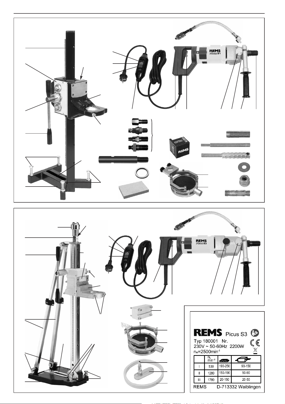
bern, Spreizanker (28) mit Kordelgewindestange (25) in Bohrloch schie-
ben.Kordelgewindestange(25) ganzeinschraubenund z. B.mitinQuer-
bohrung der Kordelgewindesstange gesteckten Schraubendreher
festziehen. Die 4 Stellschrauben (5) am Bohrständer so weit zurück-
drehen, dass sie nicht über die Grundplatte vorstehen. Bohrständer mit
Schlitz (7) auf Kordelgewindestange positionieren, dabei gewünschte
Position der Kernbohrung beachten. Scheibe (26) auf Kordelgewinde-
stange montieren und Schnellspann-Mutter (27) mit Maulschlüssel SW
19 festziehen. Alle 4 Stellschrauben (5) mit Maulschlüssel SW 19 an-
ziehen um Unebenheiten der Grundfläche auszugleichen. Darauf ach-
ten dass die Kontermuttern die Zustellung der Stellschrauben nicht be-
hindern. Bei Bedarf Kontermuttern festziehen.
Der Spreizanker kann nach Fertigstellung der Kernbohrung zur Wie-
derverwendung entfernt werden. Hierzu wird die Kordelgewindestange
ca. 10 mm zurückgedreht. Durch einen leichten Schlag auf die Kordel-
gewindestange wird der Kegel des Spreizankers freigegeben und der
Spreizanker kann entnommen werden.
3.3.3. Befestigung in Mauerwerk mit Gewindestange
Bei porösem Mauerwerk ist damit zu rechnen, dass die Dübelbefesti-
gung des Bohrständers nicht gelingt. In diesen Fällen ist zu empfehlen,
das Mauerwerk komplett zu durchbohren und den Bohrständer mit ei-
ner durchgehenden Gewindestange, z. B. M12, mit Scheiben und Mut-
tern zu befestigen.
3.3.4. Vakuumbefestigung
Für Kernbohrungen in Bauteilen mit glatter Oberfläche (z. B. Fliesen,
Marmor), bei denen keine Dübelbefestigung möglich ist, kann der Bohr-
ständer durch Vakuum festgehalten werden. Die Eignung der Bauteile
zur Vakuumbefestigung ist zu prüfen. Mit REMS Duplex und Duplex 300
ist diese Befestigungsart möglich. Die erforderlichen Teile für den Bohr-
ständer sind im Lieferumfang enthalten. Es ist wie folgt vorzugehen:
Dichtring (43) in die Nut an der Unterseite der Grundplatte (6) einlegen.
Schlitz(7)inderGrundplatte(6)mitAbdeckplattemitSchlauchanschluss
(42)verschließen.HandelsüblicheVakuumpumpeanSchlauchanschluss
(41)anschließenundBohrständeraufUnterlagefestsaugen.Unterdruck
während der Bohrarbeit ständig überprüfen (Manometeranzeige). Be-
triebsanleitung der eingesetzten Vakuumpumpe beachten. Mit gerin-
gem Vorschubdruck bohren.
3.3.5. Befestigung mit Schnellspannsäule
REMS Duplex und Duplex 300 bietet auch die Möglichkeit, den Bohr-
ständer zwischen Boden und Decke oder zwischen zwei Wänden ein-
zuspannen. Hierzu wird z. B. eine handelsübliche Schnellspannsäule
oder ein Stahlrohr 1
1
/
4
” zwischen dem Spannkopf (29) des Bohrstän-
ders und der Decke/Wand positioniert und z. B. mit in Querbohrung des
Spannkopfes gesteckten Schraubendreher gespannt. Die Kontermut-
ter (30) festziehen.
Es ist zu beachten, dass die Schnellspannsäule bzw. das Stahlrohr zur
Bohrsäule fluchtet und dass die Gewindespindel (33) mindestens
20 mm im Gewinde der Bohrsäule sowie im Gewinde des Spannkopf-
es eingeschraubt ist um eine stabile Abstützung zu gewährleisten. Zur
Verteilung des Anpressdruckes der Schnellspannsäule auf die Decke/
Wand ist eine Unterlage aus Holz oder Metall zu verwenden.
3.4. Trockenbohren mit Bohrständer
REMS Picus S1 und REMS Picus S3
Bohrständer nach einer der unter 3.3. beschriebenen Arten befestigen.
Spannhals (13) der Antriebsmaschine in Aufnahme im Spannwinkel (10)
einsteckenundZylinderschraube(n)(8)mitSechskant-StiftschlüsselSW
6festziehen.GewählteDiamant-KernbohrkroneaufAntriebsspindel(11)
der Antriebsmaschine schrauben und von Hand mit leichtem Schwung
festziehen. Anziehen mit Maulschlüssel ist nicht erforderlich.
Staubabsaugung verwenden (siehe 2.4.2.). Wird der beim Trocken-
bohren entstehende Staub nicht abgesaugt, kann die Diamant-Kern-
bohrkrone durch Überhitzen beschädigt werden. Außerdem besteht die
Gefahr, dass der im Spalt verdichtete Bohrstaub die Diamant-Kern-
bohrkrone blockiert.
Antriebsmaschine mit Schalter (21) einschalten. Schalter in gedrück-
tem Zustand durch Vorschieben der orangefarbigen Taste verriegeln.
Diamant-KernbohrkronemitdemVorschubhebel(4) langsam vorschieben
und vorsichtig anbohren. Hat die Bohrkrone ringsum gefasst, kann der
Vorschub erhöht werden. Bleibt die Antriebsmaschine aufgrund zu ho-
hen Vorschubdruckes stehen oder blockiert wegen Widerstandes im
Bohrspalt, reduziert die Multifunktions-Elektronik den Motorstrom und
somit die Drehzahl der Antriebsmaschine auf ein Minimum. Die An-
triebsmaschineschaltetjedochnichtab.WirdderVorschubdruckzurück-
genommen, steigt die Drehzahl der Antriebsmaschine wieder. Die An-
triebsmaschine nimmt bei diesem Vorgang, auch wenn er mehrmals
wiederholt wird, keinen Schaden. Bleibt jedoch trotz Reduzierung des
Vorschubdruckes der Motor weiterhin stehen, muss die Antriebsma-
schine ausgeschaltet werden und die Diamant-Bohrkrone muss ma-
nuell gelöst werden (siehe 5.). Netzstecker ziehen!
REMS Picus S2/3,5
Die beiden Schrauben (52) am Flansch des REMS Duplex 300 lösen,
REMS Picus S2/3,5 in die Führung (53) einsetzen. Antriebsmaschine
festhalten und Schrauben (52) anziehen. Gegenmutter kontern. Ge-
wählte Diamant-Kernbohrkrone auf Antriebsspindel (11) der Antriebs-
maschine schrauben und von Hand mit leichtem Schwung festziehen.
Anziehen mit Maulschlüssel ist nicht erforderlich. Antriebsmaschine mit
Schalter (21) einschalten. Diamant-Kernbohrkrone mit dem Vorschub-
hebel (4) langsam vorschieben und vorsichtig anbohren. Hat die Bohr-
krone ringsum gefasst, kann der Vorschub erhöht werden. Bleibt die An-
triebsmaschineaufgrundzuhohenVorschubdruckesstehen oder blockiert
wegen Widerstandes im Bohrspalt, reduziert die Multifunktions-Elek-
tronik den Motorstrom und somit die Drehzahl der Antriebsmaschine auf
ein Minimum. Die Antriebsmaschine schaltet jedoch nicht ab. Wird der
Vorschubdruck zurückgenommen, steigt die Drehzahl der Antriebsma-
schine wieder. Die Antriebsmaschine nimmt bei diesem Vorgang, auch
wenn er mehrmals wiederholt wird, keinen Schaden. Bleibt jedoch trotz
Reduzierung des Vorschubdruckes der Motor weiterhin stehen, muss
die Antriebsmaschine ausgeschaltet werden und die Diamant-Bohr-
krone muss manuell gelöst werden (siehe 5.). Netzstecker ziehen!
Wichtig: Stahlbeton nur nassbohren!
3.5. Nassbohren mit Bohrständer
REMS Picus S1 und REMS Picus S3
Bohrständer nach einer der unter 3.3. beschriebenen Arten befestigen.
Spannhals (13) der Antriebsmaschine in Aufnahme im Spannwinkel (10)
einsteckenundZylinderschraube(n)(8)mitSechskant-StiftschlüsselSW
6festziehen.GewählteDiamant-KernbohrkroneaufAntriebsspindel(11)
der Antriebsmaschine schrauben und von Hand mit leichtem Schwung
festziehen. Anziehen mit Maulschlüssel ist nicht erforderlich.
Wasserzuführunganschließen(siehe2.5.).AntriebsmaschinemitSchal-
ter (21) einschalten. Schalter in gedrücktem Zustand durch Vorschie-
ben der orangefarbigen Taste verriegeln. Diamant-Kernbohrkrone mit
dem Vorschubhebel langsam vorschieben und bei geringer Wasserzu-
führung vorsichtig anbohren. Hat die Bohrkrone ringsum gefasst, kann
derVorschuberhöht werden. Wasserdruckderarteinstellen,dassmäßig,
aber konstant Wasser aus dem Bohrloch austritt. Zu niedriger Wasser-
druck,beidemdasabgetrageneMaterialeherschlammig aus dem Bohr-
loch austritt, ist ebenso nachteilig für Arbeitsfortschritt und Standzeit der
Diamant-Kernbohrkrone wie zu hoher Wasserdruck, bei dem das Spül-
wasser klar aus dem Bohrloch austritt. Darauf achten, dass beim Be-
trieb kein Wasser in den Motor der Antriebmaschine gelangt. Lebens-
gefahr!
BleibtdieAntriebsmaschineaufgrundzuhohenVorschubdruckesstehen
oder blockiert wegen Widerstandes im Bohrspalt, reduziert die Multi-
funktions-Elektronik den Motorstrom und somit die Drehzahl der An-
triebsmaschine auf ein Minimum. Die Antriebsmaschine schaltet jedoch
nicht ab. Wird der Vorschubdruck zurückgenommen, steigt die Dreh-
zahl der Antriebsmaschine wieder. Die Antriebsmaschine nimmt bei die-
sem Vorgang, auch wenn er mehrmals wiederholt wird, keinen Scha-
den. Bleibt jedoch trotz Reduzierung des Vorschubdruckes der Motor
weiterhin stehen, muss die Antriebsmaschine ausgeschaltet werden
deu deu

und die Diamant-Bohrkrone muss manuell gelöst werden (siehe 5.).
Netzstecker ziehen!
REMS Picus S2/3,5
Die beiden Schrauben (52) am Flansch des REMS Duplex 300 lösen.
REMS Picus S2/3,5 in die Führung (53) einsetzen. Antriebsmaschine
festhalten und Schrauben (52) anziehen. Gegenmutter kontern. Ge-
wählte Diamant-Kernbohrkrone auf Antriebsspindel (11) der Antriebs-
maschine schrauben und von Hand mit leichtem Schwung festziehen.
Anziehen mit Maulschlüssel ist nicht erforderlich. Antriebsmaschine mit
Schalter (21) einschalten. Diamant-Kernbohrkrone mit dem Vorschub-
hebel (4) langsam vorschieben und vorsichtig anbohren. Hat die Bohr-
krone ringsum gefasst, kann der Vorschub erhöht werden. Bleibt die An-
triebsmaschineaufgrundzuhohenVorschubdruckesstehen oder blockiert
wegen Widerstandes im Bohrspalt, reduziert die Multifunktions-Elek-
tronik den Motorstrom und somit die Drehzahl der Antriebsmaschine auf
ein Minimum. Die Antriebsmaschine schaltet jedoch nicht ab. Wird der
Vorschubdruck zurückgenommen, steigt die Drehzahl der Antriebsma-
schine wieder. Die Antriebsmaschine nimmt bei diesem Vorgang, auch
wenn er mehrmals wiederholt wird, keinen Schaden. Bleibt jedoch trotz
Reduzierung des Vorschubdruckes der Motor weiterhin stehen, muss
die Antriebsmaschine ausgeschaltet werden und die Diamant-Bohr-
krone muss manuell gelöst werden (siehe 5.). Netzstecker ziehen!
3.6. Entfernen des Bohrkernes
Achtung: Beim vertikalen Durchbohren, z. B. einer Decke, löst sich der
Bohrkern normalerweise von selbst und fällt von der Decke! Vorkeh-
rungen treffen, dass keine Personen- oder Sachschäden entstehen!
Bleibt der Bohrkern nach Fertigstellung der Kernbohrung in der Dia-
mant-Kernbohrkrone hängen, so muss die Diamant-Kernbohrkrone von
der Antriebsmaschine abgeschraubt und der Bohrkern mit einem Stab
ausgestoßen werden.
Achtung: Keinesfalls darf mit Metallteilen, z. B. Hammer oder Maul-
schlüssel, auf den Mantel des Bohrrohres geschlagen werden um den
Bohrkern zu lösen. Dadurch wird das Bohrrohr nach innen gebeult und
ein zukünftiges Klemmen des Bohrkerns noch begünstigt. Die Diamant-
Kernbohrkrone kann dadurch unbrauchbar werden.
Bei nicht durchgehenden Kernbohrungen kann der Bohrkern ab einer
Bohrtiefe 1,5 x Ø gebrochen werden indem z. B. ein Meißel in den Bohr-
spalt getrieben wird. Kann der Bohrkern nicht gefasst werden, kann z.
B. mit dem Bohrhammer ein schräges Loch in den Bohrkern gebohrt
werden um diesen dann mit einem Stab zu fassen.
3.7. Verlängerung der Diamant-Kernbohrkrone
Reicht der Hub des Bohrständers oder die nutzbare Bohrtiefe der Dia-
mant-Kernbohrkrone nicht aus, ist eine Bohrkronen-Verlängerung (Zu-
behör) zu verwenden. Zunächst ist so weit wie möglich zu bohren.
Bei nicht ausreichendem Hub des Bohrständers und einer Bohrungs-
tiefe innerhalb der nutzbaren Bohrtiefe der Diamant-Kernbohrkrone ist
wie folgt vorzugehen:
Netzstecker ziehen. Diamant-Kernbohrkrone nicht aus der Kernboh-
rung ziehen. Diamant-Kernbohrkrone von der Antriebsmaschine lösen
(siehe 2.3.2.). Antriebsmaschine ohne Diamant-Kernbohrkrone zurück-
ziehen. Bohrkronen-Verlängerung (50) zwischen Diamant-Kernbohr-
krone und Antriebsmaschine montieren.
Reicht die nutzbare Bohrtiefe der Diamant-Kernbohrkrone nicht aus, ist
wie folgt vorzugehen:
Netzsteckerziehen. Diamant-Kernbohrkrone von der Antriebsmaschine
lösen (siehe 2.3.2.). Antriebsmaschine ohne Diamant-Kernbohrkrone
zurückziehen. Diamant-Kernbohrkrone aus der Kernbohrung ziehen.
Bohrkern brechen (siehe 3.6.) und aus der Kernbohrung entfernen.
Diamant-Kernbohrkrone wieder in die Bohrung einführen. Bohrkronen-
Verlängerung (50) zwischen Diamant-Kernbohrkrone und Antriebsma-
schine montieren.
4. Instandhaltung
Vor Instandsetzungs- und Reparaturarbeiten Netzstecker ziehen!
4.1. Wartung
Regelmäßig Funktion des Fehlerstrom-Schutzschalters PRCD prüfen
(siehe 3.). Antriebsmaschine und Handgriffe sauber halten. Nach Be-
endigung der Bohrarbeiten Bohrständer und Bohrkrone mit Wasser
reinigen. Lüftungsschlitze am Motor von Zeit zu Zeit ausblasen. Bohr-
kronen-AnschlussgewindeanAntriebsmaschineundAnschlussgewinde
der Diamant-Kernbohrkronen sauber halten und von Zeit zu Zeit ölen.
4.2. Inspektion/Instandsetzung
Vor Instandsetzungsarbeiten Netzstecker ziehen! Diese Arbeiten dür-
fen nur von anerkannten Fachkräften oder unterwiesenen Personen
durchgeführt werden.
Die Motoren von REMS Picus S1, REMS Picus S3 und REMS Picus
S2/3,5 haben Kohlebürsten. Diese verschleißen und müssen deshalb
von Zeit zu Zeit geprüft bzw. ersetzt werden. Es wird empfohlen, die An-
triebsmaschinen nach ca. 250 Betriebsstunden oder mindestens jähr-
lich einer autorisierten REMS Vertrags-Kundendienstwerkstatt zur In-
spektion/Instandhaltung einzureichen.
Ungeachtet dessen sind nationale Prüffristen für ortsveränderliche elek-
trische Betriebsmittel auf Baustellen zu beachten.
5. Störungen
Achtung: Antriebsmaschine nicht ein- und ausschalten, um festsitzen-
de Diamant-Kernbohrkrone zu lösen.
5.1. Störung: Diamant-Kernbohrkrone klemmt.
Ursache: Z. B. durch Trockenbohren ohne Staubabsaugung ver-
dichteter Bohrstaub.
Behebung: Antriebsmaschine ausschalten. Diamant-Kernbohrkrone
mit Maulschlüssel SW 41 solange hin und her bewegen,
bis sie wieder frei ist. Vorsichtig weiter bohren. Staubab-
saugung verwenden oder nass bohren.
5.2. Störung: Diamant-Kernbohrkrone klemmt oder schneidet schwer.
Ursache: LosesMaterialoderStahlabschnittehabensichverklemmt.
Behebung: Bohrkern brechen und lose Teile entfernen.
Ursache: Bohrrohr unrund oder beschädigt.
Behebung: Neue Diamant-Kernbohrkrone verwenden.
5.3. Störung: Diamant-Kernbohrkrone schneidet schwer.
Ursache: Falsche Drehzahl (REMS Picus S3, REMS Picus S2/3,5).
Polierte Diamant-Segmente.
Behebung: Vorschubdruck erhöhen.
Diamant-Segmenteschärfen.Hierzu10bis15mmtiefinSand-
stein, Asphalt oder in einen Schärfstein (Zubehör) bohren.
Ursache: Abgenutzte Diamant-Segmente.
Behebung: Neue Diamant-Kernbohrkrone verwenden.
5.4. Störung: Diamant-Kernbohrkronebohrtnichtan,weichtseitlichaus.
Ursache: Zu heftiges Aufsetzen der Diamant-Kernbohrkrone beim
Anbohren.
Behebung: Mit geringem Vorschub anbohren.
Ursache: Antriebsmaschine im Spannwinkel ungenügend befestigt.
Behebung: BefestigungdesSpannhalsesderAntriebsmaschineprüfen.
Ursache: BeschädigteundunrundlaufendeDiamant-Kernbohrkrone.
Behebung: Neue Diamant-Kernbohrkrone verwenden.
Ursache: Bohrständer nicht sicher befestigt.
Behebung: Befestigungsschraube und Stellschrauben festziehen.
5.5. Störung: Bohrkern hängt in der Diamant-Kernbohrkrone.
Ursache: VerdichteterBohrstauboderim Bohrrohr verklemmteTeile
des Bohrkerns.
Behebung: Keinesfalls mit Metallteilen (z. B. Hammer, Maulschlüs-
sel) auf den Mantel des Bohrrohres schlagen. Dadurch
wird das Bohrrohr nach innen gebeult und ein zukünftiges
Klemmen des Bohrkerns noch begünstigt. Die Diamant-
Kernbohrkrone kann dadurch unbrauchbar werden.
Diamant-Kernbohrkrone von der Antriebsmaschine ab-
schrauben, Bohrkern mit Stab ausstoßen, Anschlussge-
winde nicht beschädigen.
5.6. Störung: Diamant-Kernbohrkrone lässt sich nur schwer von der
Antriebsspindel lösen.
Ursache: Schmutz, Korrosion.
Behebung: Gewinde der Antriebsspindel und der Diamant-Kernbohr-
krone reinigen und leicht ölen.
deu deu

deu eng
5.7. Störung: Antriebsmaschine läuft nicht.
Ursache: Fehlerstromschutzschalter PRCD (19) nicht betätigt.
Behebung: PRCD prüfen (siehe 3.).
Elektriker hinzuziehen.
6. Hersteller-Garantie
Die Garantiezeit beträgt 12 Monate nach Übergabe des Neuproduktes
an den Erstverwender, höchstens jedoch 24 Monate nach Auslieferung
an den Händler. Der Zeitpunkt der Übergabe ist durch die Einsendung
der Original-Kaufunterlagen nachzuweisen, welche die Angaben des
Kaufdatums und der Produktbezeichnung enthalten müssen. Alle in-
nerhalb der Garantiezeit auftretenden Funktionsfehler, die nachweisbar
auf Fertigungs- oder Materialfehler zurückzuführen sind, werden ko-
stenlos beseitigt. Durch die Mängelbeseitigung wird die Garantiezeit für
das Produkt weder verlängert noch erneuert. Schäden, die auf natürli-
che Abnutzung, unsachgemäße Behandlung oder Missbrauch, Miss-
achtung von Betriebsvorschriften, ungeeignete Betriebsmittel, über-
mäßige Beanspruchung, zweckfremde Verwendung, eigene oder frem-
de Eingriffe oder andere Gründe, die REMS nicht zu vertreten hat,
zurückzuführen sind, sind von der Garantie ausgeschlossen.
Garantieleistungen dürfen nur von einer autorisierten REMS Vertrags-
Kundendienstwerkstatt erbracht werden. Beanstandungen werden nur
anerkannt, wenn das Produkt ohne vorherige Eingriffe in unzerlegtem
Zustand einer autorisierten REMS Vertrags-Kundendienstwerkstatt ein-
gereicht wird. Ersetzte Produkte und Teile gehen in das Eigentum von
REMS über.
Die Kosten für die Hin- und Rückfracht trägt der Verwender.
Die gesetzlichen Rechte des Verwenders, insbesondere seine Mängel-
ansprüche gegenüber dem Händler, bleiben unberührt. Diese Herstel-
ler-Garantie gilt nur für Neuprodukte, welche in der Europäischen Union,
in Norwegen oder in der Schweiz gekauft werden.
7. REMS Vertrags-Kundendienstwerkstätten
Firmeneigene Fachwerkstatt für Reparaturen:
SERVICE-CENTER
Neue Rommelshauser Straße 4
D-71332 Waiblingen
Telefon (0 7151) 5 68 08 - 60
Telefax (0 7151) 5 68 08 - 64
Wir holen Ihre Maschinen und Werkzeuge bei Ihnen ab!
Nutzen Sie in der Bundesrepublik Deutschland unseren Abholservice.
Einfach anrufen unter Telefon (0 7151) 5 68 08 - 60.
Oder wenden Sie sich an eine andere autorisierte REMS Vertrags-Kunden-
dienstwerkstatt in Ihrer Nähe.
General Safety Rules
WARNING! To reduce the risk of injury, user must read and understand
instruction manual.
WARNING! Read all instructions. Failure to follow all instructions listed below
may result in electric shock, fire and/or serious injury. The term „power tool“ in
all of the warnings listed below refers to your mains operated (corded) power
tool or battery operated (cordless) power tool, also machines and electric units.
Only use the power tool for the purpose for which it was intended, with the due
attention to the general safety and accident prevention regulations.
SAVE THESE INSTRUCTIONS.
A) Work area
a) Keep work area clean and well lit. Cluttered and dark areas invite acci-
dents.
b) Do not operate power tools in explosive atmospheres, such as in the
presence of flammable liquids, gases or dust. Power tools create sparks
which may ignite the dust or fumes.
c) Keep children and bystanders away while operating a power tool.
Distractions can cause you to lose control.
B) Electrical safety
a) Power tool plugs must match the outlet. Never modify the plug in any
way. Do not use any adapter plugs with earthed (grounded) power
tools. Unmodified plugs and matching outlets will reduce risk of electric
shock. If the power tool comes with an earthed wire, the plug may only be
connected to an earthed receptacle. At work sites, in damp surroundings,
in the open or in the case of comparable types of use, only operate the
power tool off the mains using a 30 mA fault current protected switch (FI
breaker).
b) Avoid body contact with earthed or grounded surfaces such as pipes,
radiators, ranges and refrigerators. There is an increased risk of electric
shock if your body is earthed or grounded.
c) Do not expose power tools to rain or wet conditions. Water entering a
power tool will increase the risk of electric shock.
Fig. 1 REMS Picus S1 and REMS Simplex
Fig. 2 REMS Picus S3 and REMS Duplex
Fig. 3 REMS Picus S2/3,5 and REMS Duplex 300
Fig. 4 Manually controlled dry boring with tapping tool
Fig. 5 Securing of drill upright with plugs in concrete, with knock-in anchor
Fig. 6 Securing of drill upright with plugs in masonry, with expansion
anchor (anchor sleeve)
Fig. 7 Machine rating plate, REMS Picus S3
Fig. 8 Machine rating plate, REMS Picus S2/3,5
Fig. 1–7:
1 Boring trestle
2 Feed slider
3 Slotted sleeve
4 Feed lever
5 Adjustment screws
6 Base plate
7 Slot
8 Fillister head screw
9 Turning handle
10 Clamping angle
11 Drive spindle
12 Holder-up
13 Drill collar
14 Cover
15 Water supply system
16 Safety switch, PRCD indicator light
17 Safety switch, PRCD RESET button
18 Safety switch, PRCD TEST button
19 Fault-current safety switch, PRCD
20 Motor handle
21 Switch
22 Adapter
23 Knock-in anchor
24 Flattener
25 Knurled threaded rod
26 Washer
27 Fast-tightening nut
28 Expansion anchor
29 Grip head
30 Locknut
33 Threaded spindle
35 Alignment hole
36 Sliding bolt
37 Screws
38 Spacer
39 Handle grip
40 Struts
41 Hose connection
42 Cover plate
43 Sealing ring
44 Water extractor unit
45 Rubber gasket
46 Suction rotor
47 Annular core bit connector,
UNC 1
1
/
4
and G
1
/
2
48 Diamond core drilling
crowns
49 Tapping tool
50 Annular core bit extension
51 Water pressure tank
52 Screws
53 Guide
54 Quick-release ring
55 Whetstone
56 Levelling block

eng eng
d) Do not abuse the cord. Never use the cord for carrying, pulling or un-
plugging the power tool. Keep cord away from heat, oil, sharp edges
or moving parts. Damaged or entangled cords increase the risk of elec-
tric shock.
e) When operating a power tool outdoors, use an extension cord suitable
for outdoor use. Use of a cord suitable for outdoor use reduces the risk of
electric shock.
C) Personal safety
a) Stay alert, watch what you are doing and use common sense when
operating a power tool. Do not use a power tool while you are tired
or under the influence of drugs, alcohol or medication. A moment of
inattention while operating power tools may result in serious personal in-
jury.
b) Use safety equipment. Always wear eye protection. Safety equipment
such as dust mask, non skid safety shoes, hard hat, or hearing protection
used for appropriate conditions will reduce personal injuries.
c) Avoid accidental starting. Ensure the switch is in the off position be-
fore plugging in. Carrying power tools with your finger on the switch or
plugging in power tools that have the switch on invites accidents.
d) Remove any adjusting key or wrench before turning the power tool
on. A wrench or a key left attached to a rotating part of the power tool may
result in personal injury.
e) Do not overreach. Keep proper footing and balance at all times. This
enables better control of the power tool in unexpected situations.
f) Dress properly. Do not wear loose clothing or jewellery. Keep your
hair, clothing and gloves away from moving parts. Loose clothes, je-
wellery or long hair can be caught in moving parts.
g) If devices are provided for the connection of dust extraction and
collection facilities, ensure these are connected and properly used.
Use of these devices can reduce dust related hazards.
h) Only allow trained personnel to use the power tool. Apprentices may
only operate the power tool when they are over 16, when this is necessary
for their training and when they are supervised by a trained operative.
D) Power tool use and care
a) Do not force the power tool. Use the correct power tool for your
application. The correct power tool will do the job better and safer at the
rate for which it was designed.
b) Do not use the power tool if the switch does not turn it on and off. Any
power tool that cannot be controlled with the switch is dangerous and must
be repaired.
c) Disconnect the plug from the power source before making any adjust-
ments, changing accessories, or storing power tools. Such preventive
safety measures reduce the risk of starting the power tool accidentally.
d) Store idle power tools out of the reach of children and do not allow
persons unfamiliar with the power tool or these instructions to ope-
rate the power tool. Power tools are dangerous in the hands of untrained
users.
e) Maintain power tools. Check for misalignment or binding of moving
parts, breakage of parts and any other condition that may affect the
power tools operation. If damaged, have the power tool repaired by a
qualified expert or by an authorised REMS after-sales service facility
before use. Many accidents are caused by poorly maintained power tools.
f) Keep cutting tools sharp and clean. Properly maintained cutting tools
with sharp cutting edges are less likely to bind and are easier to control.
g) Secure the workpiece. Use clamps or a vice to hold the workpiece. This
is safer than holding it with your hand, and also it frees both hands to ope-
rate the equipment.
h) Use the power tool, accessories and tool bits etc., in accordance with
these instructions and in the manner intended for the particular type
of power tool, taking into account the working conditions and the work
to be performed. Use of the power tool for operations different from those
intended could result in a hazardous situation. All unauthorised modifica-
tions to the power tool are prohibited for safety reasons.
E) Battery tool use and care
a) Ensure the switch is in the off position before inserting battery pack.
Inserting the battery pack into power tools that have the switch on invites
accidents.
b) Recharge only with the charger specified by the manufacturer. A char-
ger that is suitable for one type of battery may create a risk of fire when used
with another battery pack.
c) Use battery tools only with specifically designated battery packs. Use
of any other battery packs may create a risk of injury and fire.
d) When battery pack is not in use, keep it away from other metal objects
like paper clips, coins, keys, nails, screws, or other small metal objects
that can make a connection from one terminal to another. Shorting the
battery terminals may cause bums or a fire.
e) Underabusiveconditions,liquidmaybeejectedfromthebattery,avoid
contact. If contact accidentally occurs, flush with water. If liquid con-
tacts eyes, additionally seek medical help. Liquid ejected from the
battery may cause irritation or bums.
f) Do not use the battery/charger at battery/charger temperatures or
ambient temperatures of 5°C/40°F or b40°C/105°F.
g) Do not dispose defective batteries in the normal domestic waste. Take
them to an authorised REMS after-sales service facility or to a reputed
waste disposal company.
F) Service
a) Have your power tool serviced by a qualified repair person using only
identical replacement parts. This will ensure that the safety of the power
tool is maintained.
b) Comply with maintenance instructions and instructions on tool
replacements.
c) Check mains lead of power tool regularly and have it replaced by a
qualified expert or an authorised REMS after-sales service facility in
case of damage. Check extension cable regularly and replace it when
damaged.
Specific Safety Instructions
•
Use only electrical plugs with shockproof socket. Check the earth (ground)
connection of the plug.
•
Use only extension leads with shockproof socket.
•
Never use the drive unit without the PRCD fault-current safety switch sup-
plied.
•
Always check the PRCD fault-current safety switch for correct functioning
before starting a drilling operation (see 3.).
•
When drilling, hold the drive unit only by the insulated handles provided
for the purpose.
•
Ensure that no water is allowed to get into the drive unit during operation.
•
If you detect a leak in any part of the water supply system, shut the ma-
chine down immediately and repair the fault. Water pressure should not
exceed 4 bar.
•
Have the core drilling operations marked out by the person in charge of
operations.
•
The statics must not be negatively influenced in any way by the core dril-
ling work, consult site management or the engineer engaged in statical
calculations if necessary.
•
Take care not to damage gas, water, power and other conduits in the area
of the drilling operation. Drain or shut off these conduits as required.
•
Block off the working area and place warning signs on both sides of the
wall when drilling through from one side to the other.
•
Take appropriate precautions to ensure that, in the event of a drilling core
dropping out, no personal injury or material damage will result.
•
When handling hollow components, check the flow route of the diluted
soluble oil in order to prevent damage (e.g. from frost).
•
Note that the diamond core drilling crowns can become blocked at any
time. During manually controlled core drilling, there is a danger of the drive
unit jumping out of your hands.
•
Do not attempt to work above shoulder height with electrically-driven core
drilling machines.
1. Technical specifications
1.1. Article numbers
REMS Picus S1 drive unit 180000
REMS Picus S3 drive unit 180001
REMS Picus S2/3,5 drive unit 180002
Holder-up 180050
REMS Simplex drill upright 182000
REMS Duplex drill upright 182001
REMS Duplex 300 drill upright 182012
Universal diamond core drilling crowns
REMS UDKB 32 x 420 x UNC 1
1
/
4
181010
REMS UDKB 42 x 420 x UNC 1
1
/
4
181015

eng eng
REMS UDKB 52 x 420 x UNC 1
1
/
4
181020
REMS UDKB 62 x 420 x UNC 1
1
/
4
181025
REMS UDKB 72 x 420 x UNC 1
1
/
4
181030
REMS UDKB 82 x 420 x UNC 1
1
/
4
181035
REMS UDKB 92 x 420 x UNC 1
1
/
4
181040
REMS UDKB 102 x 420 x UNC 1
1
/
4
181045
REMS UDKB 112 x 420 x UNC 1
1
/
4
181050
REMS UDKB 125 x 420 x UNC 1
1
/
4
181057
REMS UDKB 132 x 420 x UNC 1
1
/
4
181060
REMS UDKB 152 x 420 x UNC 1
1
/
4
181065
REMS UDKB 162 x 420 x UNC 1
1
/
4
181070
REMS UDKB 182 x 420 x UNC 1
1
/
4
181075
REMS UDKB 200 x 420 x UNC 1
1
/
4
181080
REMS UDKB 225 x 420 x UNC 1
1
/
4
181085
REMS UDKB 250 x 420 x UNC 1
1
/
4
181090
REMS UDKB 300 x 420 x UNC 1
1
/
4
181095
Expansion anchor M12 (masonry), 10 units 079006
Knock-in anchor M12 (concrete), 50 units 079005
Flattener for knock-in anchor M12 182050
Fast-tightening nut set (art. no. 079007, 079008, 079009) 079010
Knurled threaded rod M12 x 65 079008
Fast-tightening nut 079009
Washer 079007
Tapping tool G
1
/
2
for Ø 8 mm drill 180150
Single-ended wrench SW 19 079000
Single-ended wrench SW 30 079001
Single-ended wrench SW 32 079002
Single-ended wrench SW 41 079003
Hexagon socket head wrench SW 3 079011
Hexagon socket head wrench SW 6 079004
Suction rotor for dust extraction 180160
Adapter G
1
/
2
male – UNC 1
1
/
4
male 180052
Adapter UNC 1¼ male – Hilti BI 180053
Adapter UNC 1¼ male – Hilti BU 180054
Adapter UNC 1¼ male – Würth 180055
Annular core bit extension 200 mm x UNC 1
1
/
4
180155
Sharpening stone 079012
Pressurised water tank 182006
Quick-release ring 180015
Levelling block 182009
Water suction device Simplex 182002
Water suction device Duplex 182003
1.2. Drilling depth
Useful drilling depth of the REMS Universal
diamond core drilling crown 420 mm
Deeper core-drilling operations can be carried out with the annular
core bit extension (see 3.7).
1.3. Drilling range Picus S1 Picus S3 Picus S2/3,5
Core drilling operations
in steel-reinforced
concrete Ø 20–102 Ø 20–152 Ø 40–300 mm
(132) mm (200) mm
Core-drilling operations
in masonry Ø 20–152 mm Ø 20–252 mm Ø 40–300 mm
Annular-bit connection
thread UNC 1¼ male, UNC 1¼ male, UNC 1¼
G ½ female G ½ female
Drill collar Ø 60 mm 60 mm
1.4. Turning speed Picus S1 Picus S3 Picus S2/3,5
230 V, 50–60 Hz
Idling 830 min-
1
750, 1800, 2500 min-
1
490, 1160 min-
1
At rated load 580 min-
1
530, 1280, 1780 min-
1
320, 760 min-
1
115 V, 50–60 Hz
Idling 940 min-
1
770, 1860, 2580 min-
1
440, 1030 min-
1
At rated load 740 min-
1
570, 1380, 1920 min-
1
290, 680 min-
1
1.5. Electrical specifications Picus S1 Picus S3 Picus S2/3,5
Supply voltage 230 V, 50/60 Hz
Power consumption 1800 W 2200 W 3420 W
Rated current capacity 8.4 A 10 A 16 A
Picus S1 Picus S3 Picus S2/3,5
Fuse protection
(mains network) 10 A (B) 16 A (B) 16 A (B)
Fault-current safety switch
PRCD 10 mA 10 mA 10 mA
with low-voltage release
Supply voltage 115 V, 50/60 Hz
Power consumption 1700 W 2050 W 2820 W
Rated current capacity 15 A 18 A 25 A
Fuse protection
(mains network) 20 A 25 A 25 A
Fault-current safety switch
PRCD 6 mA 6 mA 6 mA
with low-voltage release
1.6. Dimensions (L x W x H)
REMS Picus S1 drive unit 460 x 160 x 100 mm (18.1”×6.3”×3.9”)
REMS Picus S3 drive unit 540 x 160 x 100 mm (21.3”×6.3”×3.9”)
REMS Picus S2/3,5 drive unit490 x 170 x 135 mm (19.3”×6.7”×5.3”)
REMS Simplex drill upright 400 x 200 x 775 mm (15.7”×7.9”×30.5”)
REMS Duplex drill upright 440 x 230 x 935 mm (17.3”×9.1”×36.8”)
REMS Duplex 300 drill upr. 480×300×1060 mm (18.9”×11.8”×41.7”)
1.7. Weights
REMS Picus S1 drive unit 5.2 kg (11.5 lb)
REMS Picus S3 drive unit 7.4 kg (16.3 lb)
REMS Picus S2/3,5 drive unit 13.6 kg (30.0 lb)
REMS Simplex drill upright 9.7 kg (21.4 lb)
REMS Duplex drill upright 12.8 kg (28.2 lb)
REMS Duplex 300 drill upright 16.2 kg (35.8 lb)
1.8. Noise emissions Picus S1 Picus S3 Picus S2/3,5
Workplace emission level 90 dB (A) 90 dB (A) 91 dB (A)
Operating sound level 103 dB (A) 103 dB (A) 104 dB (A)
1.9. Vibrations
Weighted effective value of
acceleration 2.5 m/s
2
2.5 m/s
2
2.5 m/s
2
2. Initial startup
2.1. Electrical connection
Before connecting the machine, check to ensure that the mains volta-
ge matches that indicated on the machine rating plate. Always check
the PRCD fault current-safety switch (19) for correct functioning before
starting up at the beginning of each session (see 3.).
2.2. REMS Picus S1, REMS Picus S3 and REMS Picus S2/3,5
drive units
The REMS Picus S1, REMS Picus S3 and REMS Picus S2/3,5 drive
units are universally applicable for both dry and wet drilling, either ma-
nually controlled (Picus S1, Picus S3) or with drill upright. The combi-
ned drill crown connection of the drive spindle (11) of REMS Picus S1
and REMS Picus S3 allows both the direct mounting of diamond core
drill crowns with internal thread UNC 1¼ and with external thread G ½.
The Picus S1 and Picus S3 drive machines are not delivered with the
water feeding device (15) pre-assembled but loose. The adapter for the
water connection on the drive machines is closed by a cover (14). In this
condition the drive machines (REMS Picus S1, REMS Picus S3) are
used for dry drilling. The water feed device is already pre-assembled on
the REMS Picus S2/3,5. For wet drilling, see 2.5.
The drive-unit turning speed required for cost-effective core drilling de-
pends on the diameter of the diamond core drilling crown. Select the
turning speed of the drive unit in such a way that the peripheral speed
(cutting speed) of the diamond core drilling crown runs within a range
between 2 and 4 m/s. It is of course possible to carry out drilling opera-
tions outside this optimum range, albeit subject to reductions in the
operating speed and/or service life of the diamond core drilling crown.
Higher peripheral speed apply in masonry.
The turning speed of the REMS Picus S1 is adjusted to a fixed setting.
From a drilling diameter of 62 mm, the REMS Picus S1 operates in con-
crete in the optimum peripheral speed range, which always remains in-
side acceptable limits when smaller diameters are being handled. The

eng eng
attachmentmethodusedwiththediamond-tippedsegmentsoftheREMS
Universal diamond core drilling crown has been modified so that smal-
ler diameters can also be drilled efficiently with the REMS Picus S1.
The turning speed of the REMS Picus S3 can be selected by means of a
three-speed stepped drive to ensure that in concrete it always operates
within the optimum drilling speed range. The correct speed can be taken
from the machine rating plate (Fig. 7) of the REMS Picus S3. The first co-
lumn of the table shown there covers speeds 1 to 3, the second column
shows the corresponding turning speeds, the third column the core bit dia-
meters for masonry and the fourth column contains core bit diameters for
steel-reinforced concrete. It shows, for example, that a Ø 102 mm core-
drilling operation in masonry should be carried out in third speed, while
drilling into steel-reinforced concrete requires the use of first speed.
The turning speed of REMS Picus S2/3,5 can be selected by a 2-step
switching gear so that it always drills in an optimum area. The right ge-
ar can be read from the rating plate (Fig. 8) of REMS Picus S2/3,5. The
table there shows gears 1 and 2 in the first column and the correspon-
ding speeds in the second column and the drill crown diameters for ma-
sonry and steel-reinforced concrete in the third column.
Important: Wait for the machine to come to a halt before engaging the
transmission. Never try to do this during operation or outflow. If you can-
not engage a particular speed, turn the handle grip (39) and rotate the
drive spindle/diamond core drilling crown by hand at the same time. Pull
out the mains plug first!
2.3. Universal diamond core drilling crowns REMS UDKB
The cutting characteristics of the diamond core drilling crown are de-
termined by the quality of the diamonds, the particle-size and shape of
the diamonds, and also by the bonding agent – the metal powder in
which the diamond particles are set. Users who need to carry out a va-
riety of core-drilling operations should keep a range of diamond core
drilling crowns of different sizes to hand in order to optimise the cutting
process. It is often only possible to ascertain onsite which diamond core
drilling crown is ideal, in terms of cutting performance (operating speed)
andservice life, fora particulardrilling task.You mayeven have tocontact
the manufacturer of the diamond core drilling crown on various occa-
sions in order to find out which bit should be used.
REMS has developed the Universal diamond core drilling crown for use
in common drilling operations. These bits are universally applicable for
both dry and wet drilling, either manually-controlled or with drill upright.
The connection thread of the REMS Universal diamond core drilling
crown UNC 1
1
/
4
is compatible with the REMS Picus S1 and REMS Picus
S3, and with suitable drive units from other suppliers. If the connection
thread proves to be incompatible with the drive unit, special adapters
are available as accessories (22).
2.3.1. Fitting the diamond core drilling crown
Unplug from the mains power supply. Screw the selected diamond core
drilling crown onto the drive spindle (11) of the drive unit, and lightly
hand-tighten. It is an advantage to insert the quick-release ring (art. no.
180015) between the diamond core drill crown and the drive spindle.
There is no need to tighten it with a wrench. Note that the threads on
the drive spindle and diamond core drilling crown must be clean.
2.3.2. Removing the diamond core drilling crown
Unplug from the mains power supply. Use an SW 32 wrench to hold the
drive spindle (11) and an SW 41 wrench to loosen the diamond core
drilling crown (48).
Always unscrew the diamond core drilling crown from the drive unit when
the drilling task is finished. With wet-drilling operations in particular, there
is also a danger of the diamond core drilling crown becoming corroded,
making it difficult to remove.
Important: The casing pipes of the diamond core drilling crown are not
hardened. Hitting (with tools) and impact (during transport) on the casing
pipe will lead to damage that is likely cause the diamond core drilling
crown and/or drilling core to become seized. The diamond core drilling
crown may then be rendered unusable.
2.3.3. Sharpening the diamond core drilling crown
REMS diamond core drilling crowns are supplied ready-sharpened. If
feed pressure is kept at the correct level, the diamond-tipped segments
will sharpen themselves. Incorrect feed pressure can lead to the dia-
mond-tipped segments becoming „polished“, which causes their cutting
performance to diminish. If this occurs, use the diamond core drilling
crown to drill 10 mm to 15 mm into sandstone, asphalt or a sharpening
stone (available as an accessory) in order to sharpen the diamond-
tipped segments once more.
2.4. Manually-controlled dry boring REMS Picus S1 and
REMS Picus S3
Secure the holder-up (12) to the drill collar (13) of the drive unit.
Important: Never carry out manually-controlled drilling without first
fitting the holder-up. DANGER OF ACCIDENTS!
The water supply system (15) gets in the way of manually-controlled dry
boring, and it should therefore be disconnected. Remember to shut off
the water inlet with its sealing cap (14) to prevent dust from getting into
the machine.
Important: Always wet drilling for steel-reinforced concrete!
2.4.1. Tapping tool
Manually-controlled tapping is made considerably easier, thanks to the
REMS tapping tool (49). This is fitted with a conventional hardened-
metal Ø 8 mm masonry bit, which is secured in place with an SW 3 hexa-
gon socket head wrench. The G
1
/
2
thread is used to screw the tapping
tool into the spindle of the drive unit, where it is gently tightened with an
SW 19 wrench.
2.4.2. Dust extraction REMS Picus S1 and REMS Picus S3
We recommend the use of a dust extraction system to remove drilling
dust from the machine during core-drilling operations. This consists of
the REMS suction rotor for dust extraction (available as an accessory)
and a fine-dust suction extractor designed for industrial use. The suc-
tion rotor (46) is screwed to the drive spindle (11) of the drive unit using
the G
1
/
2
connector. The combined annular core bit connector (47) on
the opposite side permits the fitting of diamond core drilling crowns with
female thread UNC 1
1
/
4
and the attachment of the tapping tool (49).
If the dust produced by dry boring is not removed, the diamond core
drilling crown may overheat and suffer damage. There is also a danger
of the compressed drilling dust in the gap causing the diamond core
drilling crown to become blocked.
2.5. Wet boring
Optimum drilling performance will only be achieved if the diamond core
drilling crown is provided with a constant supply of water. This keeps the
diamond core drilling crown cool and allows drilled-out material to be
swilled from the bore hole. To connect the water supply system (15), re-
move the cover (14) and attach the water supply system with the fillister
head screw supplied. The quick-action coupling with water shutoff de-
vice should be fitted with a
1
/
2
” water hose. Water pressure should not
exceed 4 bar.
If there is no direct water connection available, water throughflow can
be achieved using the water pressure tank (51) (accessory). Be aware
that there is sufficient water flow.
A water extractor unit (44) (accessory) should be used if required. This
consists of a water-collection ring and a pressure ring which is secured
to the foot of the boring trestle (1). The water-collection ring is to be
connected to a wet-suction extractor designed for industrial use. The
size and shape of the rubber gasket (45) in the water-collection ring must
exactly match the diameter of the annular bit.
2.6. Boring with a drill upright
Good results can be obtained by operating with a drill upright. The pur-
pose of the drill upright is to guide the drive unit. Its power transfer rack-
and-pinion drive system ensures both hole-tapping with „feel“ and po-
werful infeed of the diamond core drilling crown. REMS Picus S1 and
REMS Picus S3 can be mounted optionally on the REMS Simplex or
REMS Duplex drill stands. REMS Picus S2/3,5 must be mounted on
REMS Duplex 300.
In the case of the REMS Simplex, the feed slider (2) supplied with the
unit must be inserted into the boring trestle (1), along with the feed lever
and clamping angle, and advanced by turning the feed lever (4). The
two reverse adjustment screws (5) should also be screwed in.
With the REMS Duplex, the clamping angle (10) and short fillister head
screws (supplied with the unit) should be screwed to the feed slider (2).

eng eng
In this configuration, the REMS Duplex can be used to drill at up to Ø
132 mm. For larger core-drilling operations, the spacer (38, supplied
with unit) must be inserted between the feed slider (2) and clamping
angle (10), and secured with the long fillister head screws. The spacer
should however only be fitted if you actually intend to drill at > Ø 132 mm,
as the drive unit runs in a more stable way without the spacer.
REMS Duplex 300 is immediately ready for operation upon delivery.
The boring trestle (1) of REMS Duplex and REMS Duplex 300 is infini-
tely adjustable up to an angle of 45°. This allows angled core-drilling
operations to be carried out within this range. To adjust the angle, use
a wrench to loosen the screws (37) at the foot of the boring trestle (1),
along with all the screws on the two struts (40). The boring trestle can
now be swivelled to the desired position. Retighten all screws before
proceeding. The swivel adjustment of the boring trestle causes the use-
ful stroke range of the feed device of the REMS Duplex to increase or
decrease accordingly. This means that you may have to use corre-
sponding annular-bit extensions (see 3.7.).
The feed slide (2) can be locked in certain positions on the drill stands.
In the case of the REMS Simplex, this is done by moving the slotted
sleeve (3) on the feed shaft, while at the same time turning the feed le-
ver axially in relation to the feed-mechanism housing until it engages.
On REMS Duplex and REMS Duplex 300, push the sliding bolt (36) in
the direction of the struts and turn the feed lever (4) at the same time
until the sliding bolt snaps into place.Locking prevents such undesired
movements as the accidental lowering of the drive unit while the dia-
mond core drilling crown is being replaced.
On the REMS Simplex, REMS Duplex and REMS Duplex 300, the feed
lever (4) can be secured, in accordance with operating conditions, on
either the right- or left-hand side of the feed slider (2). The feed slider
should be locked, as described above, when doing so. In the case of
the REMS Simplex, the turning handle (9) and two washers on the op-
posite side of the feed lever are removed; then the feed shaft is pulled
out of the feed-mechanism housing, along with the feed handle, and
pushedinagainfromtheotherside.Refitthewashersandturninghandle.
On the REMS Duplex and REMS Duplex 300, only the feed lever (4) is
pulled off the feed shaft. It is then pushed onto the shaft butt end on the
opposite side.
3. Operation
Connect by plugging into the mains supply. Always check the PRCD
fault-current safety switch (19) for correct functioning before starting a
drilling operation. To do so, press the RESET button (17) and watch for
the red indicator light (16, operating status). The indicator light should
go off when the mains plug is pulled out. Push the mains plug back into
its socket and press the RESET button. The indicator light should be
red (operating status). Press the TEST button (18), and the indicator
light should go out. Press the RESET button (17) again, and the drive
unit is ready for operation.
Important: DO NOT start drilling operations if any of the above PRCD
functions are defective! DANGER OF FATAL ACCIDENT!
Different material characteristics (concrete, steel-reinforced concrete,
porous or solid masonry) require different and varying feed pressures
on the diamond core drilling crown. Further influence is brought to bear
by the varying peripheral speed and size of the bit. It is inevitable, espe-
cially during manually controlled boring, that the machine will occasio-
nallybecomeslightlytiltedasitoperates.Thesefactors,whicharemerely
examples of those that might arise, can lead to overloading of the drive
unit during drilling operations. You will normally hear the turning speed
of the motor drop, although the diamond core drilling crown may become
completelyblocked.Thiscan lead, especiallyduringmanually-controlled
boring, to torque-related jarring – which will affect the operation.
Important: Note that the diamond core drilling crown can become blocked
at any time. During manually controlled core drilling, there is a danger
of the drive unit jumping out of your hands.
In order to simplify the handling of the machine, and to avoid damage,
the REMS Picus S1, REMS Picus S3 and REMS Picus S2/3,5 are
equipped with a multi-function electronic system, along with a mecha-
nical sliding clutch. The multi-function electronic system performs the
following tasks:
•
Initial-current limitation and jerk-free startup for smooth tapping.
•
Limiting of idling speed in order to reduce noise and prevent wear to the
motor and transmission.
•
Motor overload regulation relative to feed pressure. Before the drive unit
can be overloaded by excessive feed pressure on the diamond core dril-
ling crown, or as the result of a blockage, the motor supply current – and
thus its turning speed – is reduced to a minimum. The drive unit does
not shut down however. As the feed pressure is reduced, the turning
speed of the drive unit is increased once more. This procedure, even if
it is repeated several times in succession, prevents damage to the drive
unit. If the motor remains stopped despite the reduction in feed pres-
sure, the drive unit must be shut down and the diamond-tipped annular
bit freed manually (see 5.).
Important: DO NOT switch the drive unit on and off in an attempt to free
a blocked diamond core drilling crown.
3.1. Manually-controlled dry boring REMS Picus S1 and
REMS Picus S3
Important: Never carry out manually-controlled drilling without first
fitting the holder-up. DANGER OF ACCIDENTS!
Screw the selected diamond core drilling crown onto the drive spindle
(11) of the drive unit, and lightly hand-tighten. There is no need to tighten
it with a wrench. Using the tapping tool (see 2.4.1.). Secure the drive
unit to the motor handle (20) and holder-up (12), and locate the tapping
tool at the centre of the desired core-drilling point. Activate the drive unit
at the switch (21).
Important: Avoid accidents: NEVER block the drive unit switch during
manually-controlled boring! If the drive unit is knocked out of your hands
as a result of a blocked diamond core drilling crown, a blocked switch
can no longer be released. The drive unit will then run out of control,
and the unit must be shut down by unplugging it from the mains supply.
To make a tapping hole, drill until the diamond core drilling crown has
bored to a depth of about 5 mm. Pull out the mains plug. Remove the
tapping tool, using a SW 19 wrench if required. Using the dust-extrac-
tion system (see 2.4.2.). Continue boring until the core-drilling operation
is complete. PREVENT ACCIDENTS: The drive unit should be held
firmly throughout in order to prevent torque-related jarring. Check to en-
sure correct stability. Carry out larger core-drilling operations with the
drill upright.
If the dust produced by dry boring is not removed, the diamond core dril-
ling crown may overheat and suffer damage. There is also a danger of
the compressed drilling dust in the drilling gap causing the diamond core
drilling crown to become blocked. If you need to work without the dust-
extraction system when handling fine-pored materials, pull the diamond
core drilling crown out at regular intervals and push it back in with a slight
turn, so that the drilling dust is expelled from the drilling gap.
Important: Always wet drilling for steel-reinforced concrete!
3.2. Manually-controlled wet drilling REMS Picus S1 and
REMS Picus S3
Important: Never carry out manually-controlled drilling without first
fitting the holder-up. DANGER OF ACCIDENTS!
Screw the selected diamond core drilling crown onto the drive spindle
(11) of the drive unit, and lightly hand-tighten. There is no need to tighten
it with a wrench. Connect the water supply (see 2.5.). Using the tapping
tool (see 2.4.1.). Secure the drive unit to the motor handle (20) and
holder-up (12), and locate the tapping tool at the centre of the desired
core-drilling point. Activate the drive unit at the switch (21).
Important: Avoid accidents: NEVER block the drive unit switch during
manually-controlled boring! If the drive unit is knocked out of your hands
as a result of a blocked diamond core drilling crown, a blocked switch
can no longer be released. The drive unit will then run out of control,
and the unit must be shut down by unplugging it from the mains supply.
To make a tapping hole, drill until the diamond core drilling crown has
bored to a depth of about 5 mm. Remove the tapping tool, using a SW
19 wrench if required. Adjust the pressure in the water supply system
(15) to a point where there is a moderate, but constant, flow for water
from the bore hole. Insufficient water pressure (where the waste mate-
rial flows out of the bore hole as thick sludge rather than liquid) is as bad

eng eng
for the working efficiency and service life of the diamond core drilling
crown as is excessive water pressure, which causes completely clear
water to flow out. Continue boring until the core-drilling operation is com-
plete. PREVENT ACCIDENTS: The drive unit should be held firmly
throughout in order to prevent torque-related jarring. Check to ensure
correct stability. Carry out larger core-drilling operations with the drill
upright. Ensure that no water is allowed to get into the drive unit motor
during operation. DANGER OF FATAL ACCIDENT!
3.3. Ways of securing the drill upright
You are recommended to secure the drill upright without the drive unit
and diamond core drilling crown. The drill upright becomes top-heavy
when the drive unit is attached. This makes the task of securing it more
difficult.
3.3.1. Securing with plugs in concrete with knock-in anchor (Fig. 5)
Forcore-drillingoperationsinconcrete,thedrilluprightshouldbesecured
with a knock-in anchor (steel plug). Proceed as follows:
Mark plug hole at a distance of approx. 220 mm (Simplex and Duplex),
approx. 290 mm (Duplex 300) from the centre of the core hole. Make
the Ø 15 mm plug hole, with a drilling depth of about 55 mm. Clean the
bore hole, hit the knock-in anchor (23) in with a hammer and spread with
the flattener (24). Use only knock-in anchors of approved type (art. no.
079005). Observe approval! Screw the knurled threaded rod (25) into
the knock-in anchor and tighten it by holding a tool such as a screw-
driver in the transverse hole of the knurled threaded rod. Turn the four
adjustment screws (5) on the drill upright until they no longer protrude
from the sole plate. Position the drill upright with slot (7) on the knurled
threaded rod, while observing the desired position of the core-drilling
operation. Fit the washer (26) to the knurled threaded rod and use an
SW 19 wrench to secure the fast-tightening nut (27). Turn all four ad-
justment screws (5) with the SW 19 wrench to compensate for irregu-
larities in the ground surface. Take care to ensure that the locknuts do
not prevent movement of the adjustment screws. Tighten the locknuts
as required.
3.3.2. Securing with plugs in masonry, with expansion anchor
(anchor sleeve, fig. 6)
For core-drilling operations in masonry, the drill upright should be se-
cured with an expansion anchor (anchor sleeve). Proceed as follows:
Mark plug hole at a distance of approx. 220 mm (Simplex and Duplex),
approx. 290 mm (Duplex 300) from the centre of the core hole. Make
the Ø 20 mm plug hole, with a drilling depth of about 85 mm. Clean the
bore hole, and push the expansion anchor (28) with knurled threaded
rod (25) into the hole. Screw the knurled threaded rod (25) fully home
and tighten it by holding a tool such as a screwdriver in the transverse
hole of the rod. Turn the four adjustment screws (5) on the drill upright
until they no longer protrude from the sole plate. Position the drill upright
with slot (7) on the knurled threaded rod, while observing the desired
position of the core-drilling operation. Fit the washer (26) to the knurled
threaded rod and use an SW 19 wrench to secure the fast-tightening
nut (27). Turn all four adjustment screws (5) with the SW 19 wrench to
compensate for irregularities in the ground surface. Take care to ensu-
re that the locknuts do not prevent movement of the adjustment screws.
Tighten the locknuts as required.
The expansion anchor can be removed after completion of the core-dril-
ling operation for reuse elsewhere. To do so, turn the knurled threaded
rod back by about 10 mm. A light tap on the knurled threaded rod will
release the pin of the expansion anchor, allowing it to be removed.
3.3.3. Securing to masonry with a threaded rod
When drilling in porous masonry, note that it is not sufficient to secure
the drill upright with plugs. It is recommendable in these cases to drill
right through the masonry and secure the drill upright with a threaded
rod (e.g. M12), secured from the other side by a washer and nut.
3.3.4. Securing with vacuum suction
When carrying out core-drilling operations on items with shiny surfaces
(e.g. tiles or marble) that do not permit securing with plugs, the drill
upright can be secured by vacuum suction. Check the suitability of the
surface for vacuum suction. This method of securing is suitable for the
REMS Duplex and Duplex 300. The required drill-upright components
are supplied with the unit. Proceed as follows:
Place the sealing ring (43) into the channel on the underside of the sole
plate (6). Close off the slot (7) in the sole plate (6) with the cover plate
with hose connection (42). Attach a conventional vacuum pump to the
hose connection (41), and secure the underside of the drill upright by
suction. Check the vacuum pressure constantly during drilling (pressure
gauge). Observe the operating instructions supplied with the vacuum
pump. Operate the drill at low feed pressure.
3.3.5. Securing with a quick-action upright
The REMS Duplex and Duplex 300 also offers the possibility of secu-
ring the drill upright between the floor and ceiling, or between two walls.
This is done, for example, by placing a conventional quick-action upright
or a 1
1
/
4
” steel pipe between the grip head (29) of the drill upright and
the ceiling/wall, and tightening it by holding a tool such as a screwdriver
in the transverse hole. Tighten the locknut (30).
Note that the quick-action upright or steel pipe must be aligned with the
boring trestle, and that the threaded spindle (33) should be screwed by
at least 20 mm into the thread of the boring trestle, and into the thread
of the grip head, in order to guarantee a stable support. Use a piece of
wood or metal to distribute the pressure force of the quick-action upright
evenly on the ceiling or wall.
3.4. Dry-boring with drill upright
REMS Picus S1 and REMS Picus S3
Secure the drill upright using one of the methods described in 3.3. Insert
the drill collar (13) of the drive unit into the mounting in the clamping
angle (10), and tighten the fillister head screw(s) (8) with an SW 6 hexa-
gonsocket head wrench.Screw the selecteddiamond core drillingcrown
onto the drive spindle (11) of the drive unit, and lightly hand-tighten.
There is no need to tighten it with a wrench.
Using the dust-extraction system (see 2.4.2.). If the dust produced by
dry boring is not removed, the diamond core drilling crown may overheat
and suffer damage. There is also a danger of the compressed drilling
dust in the gap causing the diamond core drilling crown to become
blocked.
Activate the drive unit at the switch (21). Push in the switch and press
the orange button forward to lock it. Slowly advance the diamond core
drilling crown with the feed lever (4), and carefully tap the drill hole. Once
the annular bit has engaged all-round, the feed rate can be increased.
If the drive unit is stopped due to excessive feed pressure, or becomes
blocked as a result of resistance in the drilling gap, the multi-function
electronicsystem reducesthe motor current – and thus the turning speed
of the drive unit – to a minimum. The drive unit does not shut down how-
ever. As the feed pressure is reduced, the turning speed of the drive unit
is increased once more. This procedure, even if it is repeated several
times in succession, prevents damage to the drive unit. If the motor
remains stopped despite the reduction in feed pressure, the drive unit
must be shut down and the diamond-tipped annular bit freed manually
(see 5.). Pull out the mains plug!
REMS Picus S2/3,5
Loosen the two screws (52) on the flange of the REMS Duplex 300, in-
sert REMS Picus S2/3,5 in the guide (53). Hold the drive machine and
tighten the screws (52). Tighten the locking nut. Screw the selected dia-
mond core drill crown to the drive spindle (11) of the drive machine and
tighten by hand with a slight swing. There is no need to use an open-
ended wrench for tightening. Switch on drive machine with switch (21).
Push in the switch and press the orange button forward to lock it. Slowly
advance the diamond core drilling crown with the feed lever (4), and
carefully tap the drill hole. Once the annular bit has engaged all-round,
the feed rate can be increased. If the drive unit is stopped due to ex-
cessive feed pressure, or becomes blocked as a result of resistance in
the drilling gap, the multi-function electronic system reduces the motor
current – and thus the turning speed of the drive unit – to a minimum.
The drive unit does not shut down however. As the feed pressure is re-
duced, the turning speed of the drive unit is increased once more. This
procedure, even if it is repeated several times in succession, prevents
damage to the drive unit. If the motor remains stopped despite the re-
duction in feed pressure, the drive unit must be shut down and the dia-
mond-tipped annular bit freed manually (see 5.). Pull out the mains plug!
Important: Always wet drilling for steel-reinforced concrete!

eng eng
3.5. Wet-boring with drill upright
REMS Picus S1 und REMS Picus S3
Secure the drill upright using one of the methods described in 3.3. Insert
the drill collar (13) of the drive unit into the mounting in the clamping
angle (10), and tighten the fillister head screw(s) (8) with an SW 6 hexa-
gonsocket head wrench.Screw the selecteddiamond core drillingcrown
onto the drive spindle (11) of the drive unit, and lightly hand-tighten.
There is no need to tighten it with a wrench.
Connect the water supply (see 2.5.). Activate the drive unit at the switch
(21). Push in the switch and press the orange button forward to lock it.
Slowly advance the diamond core drilling crown with the feed lever, and
– with the water supply at a minimum – carefully tap the drill hole. Once
the annular bit has engaged all-round, the feed rate can be increased.
Adjust the water pressure to a point where there is a moderate, but
constant, flow for water from the bore hole. Insufficient water pressure
(where the waste material flows out of the bore hole as thick sludge
rather than liquid) is as bad for the working efficiency and service life of
the diamond core drilling crown as is excessive water pressure, which
causescompletelyclearwatertoflowout. Ensure that nowaterisallowed
to get into the drive unit motor during operation. DANGER OF FATAL
ACCIDENT!
If the drive unit is stopped due to excessive feed pressure, or becomes
blocked as a result of resistance in the drilling gap, the multi-function elec-
tronic system reduces the motor current – and thus the turning speed of
the drive unit – to a minimum. The drive unit does not shut down how-
ever. As the feed pressure is reduced, the turning speed of the drive unit
is increased once more. This procedure, even if it is repeated several
times in succession, prevents damage to the drive unit. If the motor re-
mains stopped despite the reduction in feed pressure, the drive unit must
be shut down and the diamond-tipped annular bit freed manually (see 5.).
Pull out the mains plug!
REMS Picus S2/3,5
Loosen the two screws (52) on the flange of the REMS Duplex 300, in-
sert REMS Picus S2/3,5 in the guide (53). Hold the drive machine and
tighten the screws (52). Tighten the locking nut. Screw the selected dia-
mond core drill crown to the drive spindle (11) of the drive machine and
tighten by hand with a slight swing. There is no need to use an open-
ended wrench for tightening. Switch on drive machine with switch (21).
Push in the switch and press the orange button forward to lock it. Slowly
advance the diamond core drilling crown with the feed lever (4), and
carefully tap the drill hole. Once the annular bit has engaged all-round,
the feed rate can be increased. If the drive unit is stopped due to ex-
cessive feed pressure, or becomes blocked as a result of resistance in
the drilling gap, the multi-function electronic system reduces the motor
current – and thus the turning speed of the drive unit – to a minimum.
The drive unit does not shut down however. As the feed pressure is re-
duced, the turning speed of the drive unit is increased once more. This
procedure, even if it is repeated several times in succession, prevents
damage to the drive unit. If the motor remains stopped despite the re-
duction in feed pressure, the drive unit must be shut down and the dia-
mond-tipped annular bit freed manually (see 5.). Pull out the mains plug!
3.6. Removal of the drilling core
Important: When carrying out vertical drilling, e.g. in a ceiling, note that
the drilling core normally drops out as soon as the hole is complete! Take
appropriate steps to ensure that personal injury or material damage does
not result.
If the drilling core remains hanging in the diamond core drilling crown
after the core-drilling operation is complete, the bit must be unscrewed
from the drive unit and the drilling core knocked out with a rod.
Important: NEVER hit the casing of the drilling core with a metal item
such as a hammer or wrench in order to loosen the drilling core. This
will cause the casing pipe to become dented, which will make blocking
of the drilling core even more likely on future occasions. The diamond
core drilling crown may then be rendered unusable.
If the core-drilling operation does not penetrate fully, the drilling core can
be broken up, down to a depth of 1.5 x Ø, by inserting a tool such as a
chisel into the drilling gap. If the drilling core cannot be secured, use a
tool such as a hammer drill to make an angled hole into the drilling core,
and insert a rod to extract it.
3.7. Extending the diamond core drilling crown
If the stroke distance of the drill upright, or the useful drilling depth of the
diamondcoredrillingcrown,isinsufficient,anannular-bitextension(avai-
lable as an accessory) should be used. Start by drilling in as far as pos-
sible in the normal way.
If the stroke distance of the drill upright, and boring depth within the
usable boring depth of the diamond core drilling crown, are insufficient,
proceed as follows:
Unplug from the mains power supply. Do not pull the diamond core dril-
ling crown out of the core-drilling hole. Detach the diamond core drilling
crown from the drive unit (see 2.3.2.). Turn back the drive unit without
the diamond core drilling crown. Fit the annular-bit extension (50) bet-
ween the diamond core drilling crown and drive unit.
If the usable drilling depth of the diamond-tipped annular core is insuf-
ficient, proceed as follows:
Unplug from the mains power supply. Detach the diamond core drilling
crown from the drive unit (see 2.3.2.). Turn back the drive unit without
the diamond core drilling crown. Pull the diamond core drilling crown out
of the core-drilling hole. Break up the drilling core (see 3.6.), and remove
it from the core-drilling hole. Reinsert the diamond core drilling crown
into the hole. Fit the annular-bit extension (50) between the diamond
core drilling crown and drive unit.
4. Maintenance
Always disconnect at the mains plug before carrying out servicing or
repair work.
4.1. Maintenance
Carry out regular checks of the PRCD fault-current safety switch (see
3.). Keep the drive unit and handles clean. When the drilling operation
is complete, clean the drill upright and annular bit with water. Blow out
the ventilation opening of the motor from time to time with a compres-
sed-air hose. Keep the crown connection thread on the drive unit and
the connection thread on the diamond core drilling crown clean and
apply oil from time to time.
4.2. Inspection/Maintenance
Always unplug the unit from the mains supply before carrying out main-
tenance work. These tasks must be carried out by properly qualified or
suitably trained persons.
The motors of the REMS Picus S1, REMS Picus S3 and REMS Picus
S2/3,5 are fitted with carbon brushes. These are subject to wear, and
must be checked at regular intervals and replaced as required. We re-
commend having the drive units inspected and maintained after every
250 operating hours, or at least once a year, by an authorised REMS
customer service provider.
This is independent of any local rules that may apply with respect to the
operation of electrical equipment on construction sites.
5. Troubleshooting
Important: DO NOT switch the drive unit on and off in an attempt to free
a blocked diamond core drilling crown.
5.1. Fault: diamond core drilling crown jams.
Cause: Possibly caused by compressed drilling dust resulting from
dry-boring without a dust extraction system.
Remedy: Switch off drive unit. Use an SW 41 wrench to turn the dia-
mond core drilling crown back and forth in order to free it.
Carefully continue the drilling operation. Use a dust extrac-
tion system, or wet-boring.
5.2. Fault: diamond core drilling crown jams or cuts only with difficulty.
Cause: Loose material or metal debris have jammed up the mecha-
nism.
Remedy: Break up the drilling core and remove loose items.
Cause: Casing pipe is out-of-true or damaged.
Remedy: Use a new diamond core drilling crown.
5.3. Fault: diamond core drilling crown cuts with difficulty.
Cause: Incorrectturningspeed(REMSPicusS3,REMSPicusS2/3,5).
Polished diamond-tipped segments.

eng fra
Remedy: Increase feed pressure.
Sharpen the diamond-tipped segments. This is done by dril-
ling into sandstone, asphalt or a sharpening stone (available
as an accessory) to a depth of 10 mm to 15 mm.
Cause: Worn diamond-tipped segments.
Remedy: Use a new diamond core drilling crown.
5.4. Fault: diamond core drilling crown does not tap a hole, or slips to
one side.
Cause: Excess pressure on the diamond core drilling crown during
tapping.
Remedy: Operate at a reduced feed rate.
Cause: The drive unit is incorrectly secured to the clamping angle
Remedy: Check the drill collar to ensure that it is correctly attached to
the drive unit.
Cause: Damaged or out-of-true diamond core drilling crown.
Remedy: Use a new diamond core drilling crown.
Cause: Drill upright not properly secured.
Remedy: Tighten fixing screw and adjustment screws.
5.5. Fault: Drilling core remains hanging in diamond core drilling crown.
Cause: Compressed drilling dust in casing pipe jams parts of the
drilling core.
Remedy: DO NOT knock the casing pipe with metal objects of any kind
(e.g. hammer, wrench). This will cause the casing pipe to be-
come dented, which will make blocking of the drilling core
even more likely on future occasions. The diamond core dril-
ling crown may then be rendered unusable.
Unscrew the diamond core drilling crown from the drive unit,
eject the drilling core with a rod, taking care not to damage
the connection thread.
5.6. Fault: diamond core drilling crown is detached from drive spindle
with difficulty.
Cause: Dirt, corrosion.
Remedy: Clean and slightly oil the thread of the drive spindle and the
diamond core drilling crown.
5.7. Fault: Drive unit will not run.
Cause: Fault-current safety switch PRCD (19) not actuated.
Remedy: Check PRCD (see 3.).
Contact an electrician.
6. Manufacturer’s Warranty
The warranty period shall be 12 months from delivery of the new product
to the first user but shall be a maximum of 24 months after delivery to the
Dealer. The date of delivery shall be documented by the submission of
the original purchase documents, which must include the date of purchase
and the designation of the product. All functional defects occurring within
the warranty period, which clearly the consequence of defects in produc-
tion or materials, will be remedied free of charge. The remedy of defects
shall not extend or renew the guarantee period for the product. Damage
attributable to natural wear and tear, incorrect treatment or misuse, failure
to observe the operational instructions, unsuitable operating materials,
excessive demand, use for unauthorized purposes, interventions by the
Customer or a third party or other reasons, for which REMS is not res-
ponsible, shall be excluded from the warranty.
Services under the warranty may only be provided by customer service
stations authorized for this purpose by REMS. Complaints will only be
accepted if the product is returned to a customer service station autho-
rized by REMS without prior interference in an unassembled condition.
Replaced products and parts shall become the property of REMS.
The user shall be responsible for the cost of shipping and returning the
product.
The legal rights of users, in particular the right to claim damages from the
Dealer, shall not be affected. This manufacturer’s warranty shall apply only
to new products purchased in the European Union, in Norway or Swit-
zerland.
Remarques générales pour la sécurité
ATTENTION! Toutes les directives doivent être lues. Le non-respect des di-
rectives enumérées ci-après peuvent entraîner une décharge électrique, des
brûlures, et/ou des graves blessures. Le terme utilisé ci-après „appareil élec-
trique“ se réfère aux outils électriques sur secteur (avec câble de réseau),
aux outils électriques sur accu (sans câble de réseau), aux machines et aux
outils électriques. N'utiliser l'appareil que pour accomplir les tâches pour les-
quelles il a été spécialement conçu et conformément aux prescriptions re-
latives à la sécurité du travail et à la prévention des accidents.
CONSERVER PRECIEUSEMENT CES DIRECTIVES.
A) Poste de travail
a) Maintenir le poste de travail propre et rangé. Le désordre et un poste
de travail non éclairé peut être source d'accident.
b) Ne pas travailler avec l'appareil électrique dans un milieu où il existe
un risque d'explosion, notamment en présence de liquides, de gaz
ou de poussières inflammables. Les appareils électriques produisent
des étincelles, qui peuvent mettre le feu à la poussière ou aux vapeurs.
c) Tenir les enfants et des tierces personnes à l'écart pendant l'utilisa-
tion de l'appareil électrique. Il y a un risque de perte de contrôle de la
machine en cas de distraction.
B) Sécurité électrique
a) La fiche mâle de l'appareil électrique doit être appropriée à la prise
de courant. La fiche mâle ne doit en aucun cas être modifée. Ne pas
utiliser d'adaptateur de fiche mâle avec un appareil électrique avec
mise à la terre. Des fiches mâles non modifiées et des prises de courant
appropriées réduisent le risque d'une décharge électrique. Si l'appareil
Fig. 1 REMS Picus S1 et REMS Simplex
Fig. 2 REMS Picus S3 et REMS Duplex
Fig. 3 REMS Picus S2/3,5 et REMS Duplex 300
Fig. 4 Carottage à sec à guidage manuel avec guide d'amorce
Fig. 5 Fixation de la colonne de carottage dans le béton avec des
chevilles d'ancrage
Fig. 6 Fixation de la colonne de carottage dans un mur maçonné avec
cheville écarteurs (ancre à cuvette)
Fig. 7 Plaque signalétique REMS Picus S3
Fig. 8 Plaque signalétique REMS Picus S2/3,5
Fig. 1–7:
1 Colonne de carottage
2 Chariot d'avance
3 Douille fendue
4 Levier d'avance
5 Vis de réglage
6 Socle
7 Fente
8 Vis cylindrique
9 Poignée tournante
10 Pièce de serrage
11 Broche d'entraînement
12 Poignée
13 Col de serrage
14 Couvercle
15 Dispositif d'amenée d'eau
16 Interrupteur de sécurité témoin
lumineux
17 Interrupteur de sécurité touche
RESET
18 Interrupteur de sécurité touche TEST
19 Interrupteur de sécurité F1 (déclen-
chement par courant de défaut)
20 Poignée moteur
21 Interrupteur
22 Adaptateur
23 Cheville d'ancrage
24 Chasse
25 Tige filetée à moletage
26 Rondelle
27 Ecrou de serrage rapide
28 Cheville écarteurs
29 Tête de serrage
30 Contre-écrou
33 Tige filetée
35 Trou de positionnement
36 Verrou
37 Vis
38 Entretoise
39 Manette commutatrice
40 Jambe de force
41 Raccord tuyau
42 Couvercle
43 Joint
44 Dispositif d'aspiration
d'eau
45 Rondelle caoutchouc
46 Rotor d'aspiration
47 Raccord pour couronnes
de carottage UNC 1
1
/
4
et G
1
/
2
48 Couronne de carottage
diamantée
49 Guide d'amorce de
carottage
50 Rallonge des couronnes
de carottage
51 Réservoir d’eau sous
pression
52 Vis
53 Flasque de fixation
54 Anneau pour dévissage
facile
55 Pierre à affûter
56 Bloc de niveau

fra fra
est doté d'un conducteur de protection, ne brancher la fiche mâle que sur
une prise de courant avec mise à la terre. Sur chantier, en plein air ou sur
un autre mode d'installation, n'utiliser l'appareil électrique qu'avec un dis-
positif de protection à courant de défaut de 30 mA (déclencheur par cou-
rant de défaut) sur réseau.
b) Eviter le contact avec des surfaces avec mise à la terre, comme les
tubes, radiateurs, cuisinières et réfrigérateurs. Il y a un risque élevé
de décharge électrique lorsque le corps est en contact avec la terre.
c) Tenir l'appareil électrique à l'écart de la pluie ou de milieux humides.
La pénétration d'eau dans un appareil électrique augmente le risque de
décharge électrique.
d) Ne pas utiliser le câble pour des fins auxquelles il n'a pas été prévu,
notamment pour porter l'appareil, l'accrocher ou pour débrancher
l'appareil en tirant sur la fiche mâle. Tenir le câble éloigné de la cha-
leur, de l'huile, des angles vifs et des pièces de l'appareil en mou-
vement. Des câbles endommagés ou emmêlés augmentent le risque
d'une décharge électrique.
e) Si vous travaillez avec l'appareil électrique à l'extérieur, n'utiliser que
des rallonges autorisées pour les travaux à l'extérieur. L'utilisation
d'une rallonge appropriée pour l'extérieur réduit le risque d'une décharge
électrique.
C) Sécurité des personnes
a) Etre attentif, veiller à ce que l'on fait et se mettre au travail avec bon
sens si l'on utilise un appareil électrique. Ne pas utiliser l'appareil
électrique en étant fatigué ou en étant sous l'influence de drogues,
d'alcools ou de médicaments. Un moment d'inattention lors de l'utili-
sation de l'appareil peut entraîner de sérieuses blessures.
b) Porter des équipements de protection personnels et toujours des
lunettes de protection. Le port d'équipements de protection personnels,
comme un masque respiratoire, des chaussures de sécurité anti-déra-
pantes, un casque de protection ou une protection acoustique selon le
type de l'utilisation de l'appareil électrique, réduit le risque de blessures.
c) Eviter toute utilisation involontaire ou incontrôlée. Veiller à ce que
l'interrupteur soit en position „O“ avant l'enfichage sur la prise de
courant. Porter un appareil électrique avec le doigt sur l'interrupteur ou
brancher un appareil allumé au secteur peut entraîner des accidents. Ne
jamais ponter un interrupteur.
d) Retirer les outils de réglage ou tournevis, avant la mise en service
de l'appareil électrique. Un outil ou une clé se trouvant dans une pièce
del'appareilenmouvementpeutentraîner des blessures.Nejamais porter
de main dans des pièces en mouvement (tournantes).
e) Ne pas se sur-estimer. Veiller à une position sûre et garder l'équi-
libre à tout moment. De ce fait, l'appareil peut être mieux contrôlé dans
des situations inattendues.
f) Porterdesvêtements appropriés. Ne pasporter de vêtementsamples,
ni de bijoux. Ecarter les cheveux, les vêtements et les gants des
pièces en mouvement. Des vêtements amples, des bijoux ou des che-
veux longs pourraient être happés par des pièces en mouvement.
g) Si des dispositifs d'aspiration et de réception de poussière peuvent
être montés, veiller à ce qu'ils soient branchés et utilisés correcte-
ment. L'utilisation de ces dispositions réduit les dangers liés à la pous-
sière.
h) Ne céder l'appareil électrique qu'à du personnel spécialement formé.
Utilisation interdite aux jeunes gens de moins de 16 ans, sauf en cas de
formation professionnelle et sous surveillance d'une personne qualifiée.
D) Manipulation et utilisation méticuleuse d'appareils électriques
a) Ne pas surcharger l'appareil électrique. Utiliser l'appareil électrique
approprié à votre travail. Avec les appareils électriques adéquats, le
travail est meilleur et plus sûr dans la marge de puissance indiquée.
b) Ne pas utiliser d'appareils électriques dont l'interrupteur est défec-
tueux. Un appareil électrique qui ne s'allume ou ne s'éteint plus est
dangereux et doit être réparé.
c) Retirer la fiche mâle de la prise de courant avant d'effectuer des
réglages sur l'appareil, de changer des pièces ou de ranger l'appa-
reil. Cette mesure de sécurité empêche une mise en marche involontaire
de l'appareil.
d) Tenir des appareils électriques inutilisés hors de portée des enfants.
Ne pas céder l'appareil électrique à des personnes dont son utilisa-
tion ne leur est pas familière ou qui n'ont pas lu ces directives. Les
appareils électriques sont dangereux s'ils sont utilisés par des personnes
non expérimentés.
e) Prendre scrupuleusement soin de l'appareil électrique. Contrôler si
les pièces de l'appareil en mouvement fonctionnement impecca-
blement et si elles ne coincent pas, si des pièces sont cassées ou
endommagées, si le fonctionnement de l'appareil électrique est pré-
judiciable. Avant l'utilisation de l'appareil électrique, faire réparer les
pièces endommagées par des professionnels qualifiés ou par une
station S.A.V. agrée sous contrat avec REMS. De nombreux accidents
sont dûs à la mauvaise maintenance des outils électriques.
f) Tenir les outils de coupe aiguisés et propres. Des outils de coupe avec
des arêtes aiguisées scrupuleusement soignés coincent moins et sont
plus faciles à utiliser.
g) Consolider la pièces à usiner. Utiliser des dispositifs de serrage ou un
étau pour immobiliser la pièce à usinier. Ainsi, elle est mieux retenue qu'à
lamainetenpluslesdeuxmainssontlibrespourlemaniementdel'appareil.
h) Utiliser les appareils électriques, les accessoires, les outils etc. con-
formément à ces directives et comme cela est prescrit pour ce type
spécifique d'appareil. Tenir compte des conditions de travail et de
la tâche à réaliser. Utiliser les appareils électriques pour accomplir des
tâches différentes de celles pour lesquelles ils ont été conçus, peut en-
traîner des situations dangereuses. Pour des raisons de sécurité, toute
modification injustifiée sur l'appareil électrique est formellement interdite.
E) Manipulation et utilisation méticuleuse d'appareils sur accu
a) S'assurerquel'appareilélectriqueestéteint,avantdebrancherl'accu.
Le branchement d'un accu sur un appareil électrique en marche peut en-
traîner des accidents.
b) Charger les accus uniquement avec les chargeurs recommandés
par le fabricant. Il y a un risque d'incendie si un chargeur, approprié pour
un type précis d'accus, est utilisé avec d'autres accus.
c) N'utiliser que les accus prévus à cet effet avec les appareils électri-
ques. L'utilisation d'autres accus peut entraîner des blessures et des
risques d'accident.
d) Tenir l'accu non utilisé éloigné de trombones de bureau, pièces de
monnaie, clés, clous, vis ou autres petits objets métalliques pouvant
provoquer un court-circuit entre les bornes de l'accu. Un court-cir-
cuit entre les bornes de l'accu peut provoquer des blessures et un risque
d'incendie.
e) En cas de mauvaise utilisation, il peut y avoir des fuites de liquide.
Eviter le contact avec ce liquide. En cas de contact, rincer à l'eau. Si
le liquide pénètre dans les yeux, rincer à l'eau et consulter immé-
diatement un médecin. Des fuites de liquide provenant de l'accu peu-
vent entraîner des irritations de la peau ou des brûlures.
f) Ne pas utiliser le chargeur si les températures du chargeur ou les
températuresambiantessontinférieuresà5°C/40°Foub40°C/105°F.
g) Ne pas jeter les accus défectueux dans les ordures ménagères, mais
les remettre à une station S.A.V. agrée, sous contrat avec REMS ou
à une société reconnue pour le traitement des déchets.
F) Service après vente
a) Faire réparer son appareil uniquement par des professionnels qua-
lifés en utilisant des pièces d'origines. Cela garantit le maintien de la
sécurité de l'appareil.
b) Suivre les prescriptions de maintenance et les recommandations
pour le changement des outils.
c) Contrôler régulièrement le câble de raccordement de l'appareil élec-
trique et le faire remplacer s'il est endommagé par un professionnel
qualifié ou par une station S.A.V. agrée, sous contrat avec REMS.
Contrôler régulièrement les rallonges et les remplacer si elles sont
endommagées.
Mesures spéciales de sécurité
•
N'utiliser que des prises de courant avec mise à terre. Vérifier la mise à
terre de la prise.
•
N'utiliser que des rallonges avec contact de mise à la terre.
•
Ne jamais utiliser la machine d'entraînement sans l'interrupteur de sécu-
rité F1, livré avec la machine.
•
Avant tout démarrage, vérifier le fonctionnement de l'interrupteur F1 (voir
3).
•
Ne manipuler la machine d'entraînement, en marche, que par l'intermé-
diaire des poignées isolées.
•
Pendant la marche, il faut éviter la pénétration d'eau dans le moteur de
la machine d'entraînement.
•
S'il y a des fuites sur le dispositif d'amenée d'eau, il faut immédiatement
Other manuals for Picus S1
4
This manual suits for next models
2
Table of contents
Languages:
Other REMS Drill manuals