deu deu
3.2. Handgeführtes Nassbohren REMS Picus S1, Picus S3 und Picus SR
Achtung: Handgeführt nur mit montiertem Gegenhalter arbeiten (Unfallgefahr)!
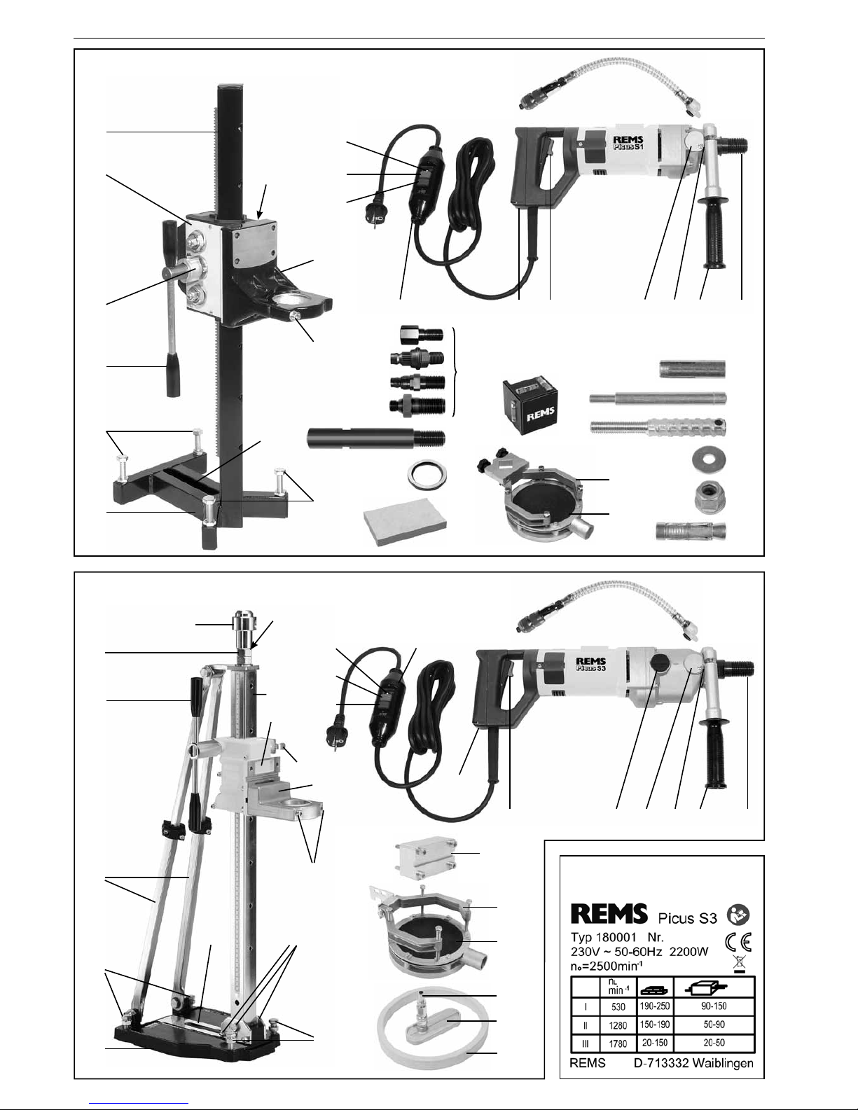
Gewählte Diamant-Kernbohrkrone aufAntriebsspindel (11) der Antriebsmaschine
schrauben und von Hand mit leichtem Schwung festziehen. Anziehen mit
Maulschlüssel ist nicht erforderlich. Wasserzuführung anschließen (siehe 2.5.).
Anbohrhilfe verwenden (siehe 2.4.1.). Antriebsmaschine am Motorgriff (20) und
am Gegenhalter (12) festhalten und dieAnbohrhilfe im Zentrum der gewünschten
Kernbohrung ansetzen. Antriebsmaschine mit Schalter (21) einschalten.
Achtung: Schalter der Antriebsmaschine beim handgeführten Bohren niemals
verriegeln (Unfallgefahr)! Sollte dieAntriebsmaschine durch eine blockierende
Diamant-Kernbohrkrone aus der Hand geschlagen werden, kann ein verriegelter
Schalter nicht mehr entriegelt werden. Die Antriebsmaschine schlägt dann
unkontrolliert um und kann nur noch durch Ziehen des Netzsteckers zum
Stillstand gebracht werden.
Anbohren bis die Diamant-Kernbohrkrone ca. 5 mm tief gebohrt hat. Anbohrhilfe
herausschrauben, gegebenenfalls mit Maulschlüssel SW19 lösen. Wasserdruck
der Wasserzuführeinrichtung (15) derart einstellen, dass mäßig, aber konstant
Wasser aus dem Bohrloch austritt. Zu niedriger Wasserdruck, bei dem das
abgetragene Material eher schlammig aus dem Bohrloch austritt, ist ebenso
nachteilig für Arbeitsfortschritt und Standzeit der Diamant-Kernbohrkrone wie
zu hoher Wasserdruck, bei dem das Spülwasser klar aus dem Bohrloch austritt.
Weiter bohren bis Kernbohrung fertiggestellt ist. Die Antriebsmaschine dabei
immer fest halten um Drehmomentstöße sicher auffangen zu können (Unfall-
gefahr!). Auf sicheren Stand achten. Größere Kernbohrungen mit Bohrständer
durchführen. Darauf achten, dass beim Betrieb kein Wasser in den Motor der
Antriebmaschine gelangt. Lebensgefahr!
3.3. Befestigungsarten des Bohrständers
Es wird empfohlen, den Bohrständer ohne Antriebsmaschine und Diamant-
Kernbohrkrone zu befestigen. Mit montierterAntriebsmaschine ist der Bohrständer
kopastig. Dadurch wird die Befestigung erschwert.
3.3.1. Dübelbefestigung in Beton mit Einschlaganker (Fig. 5)
Für Kernbohrungen in Beton wird der Bohrständer vorzugsweise mit einem
Einschlaganker (Stahldübel) befestigt. Es ist wie folgt vorzugehen:
Dübelbohrung im Abstand von ca. 220 mm (Simplex und Duplex), ca. 290 mm
(Duplex 300) zur Mitte der Kernbohrung anzeichnen. Dübelbohrung Ø 15 mm
setzen, Bohrtiefe ca. 55 mm einhalten. Bohrloch säubern, Einschlaganker (23)
mit Hammer einschlagen und mit Setzeisen (24) spreizen. Nur Einschlaganker
mit Zulassung (Art.-Nr. 079005) verwenden. Zulassung beachten! Kordelge-
windestange (25) in Einschlaganker schrauben und z. B. mit in Querbohrung
der Kordelgewindestange gesteckten Schraubendreher festziehen. Die 4
Stellschrauben (5) am Bohrständer so weit zurückdrehen, dass sie nicht über
die Grundplatte vorstehen. Bohrständer mit Schlitz (7) auf Kordelgewindestange
positionieren, dabei gewünschte Position der Kernbohrung beachten. Scheibe
(26) auf Kordelgewindestange montieren und Schnellspann-Mutter (27) mit
Maulschlüssel SW 19 festziehen. Alle 4 Stellschrauben (5) mit Maulschlüssel
SW 19 anziehen um Unebenheiten der Grundäche auszugleichen. Darauf
achten dass die Kontermuttern die Zustellung der Stellschrauben nicht behin-
dern. Bei Bedarf Kontermuttern festziehen.
3.3.2. Dübelbefestigung in Mauerwerk mit Spreizanker (Ankerschalen) (Fig. 6)
Für Kernbohrungen in Mauerwerk wird der Bohrständer vorzugsweise mit einem
Spreizanker (Ankerschalen) befestigt. Es ist wie folgt vorzugehen:
Dübelbohrung im Abstand von ca. 220 mm (Simplex und Duplex), ca. 290 mm
(Duplex 300) zur Mitte Kernbohrung anzeichnen. Dübelbohrung Ø 20 mm
setzen, Bohrtiefe ca. 85 mm einhalten. Bohrloch säubern, Spreizanker (28) mit
Kordelgewindestange (25) in Bohrloch schieben. Kordelgewindestange (25)
ganz einschrauben und z. B. mit in Querbohrung der Kordelgewindesstange
gesteckten Schraubendreher festziehen. Die 4 Stellschrauben (5) am Bohr-
ständer so weit zurückdrehen, dass sie nicht über die Grundplatte vorstehen.
Bohrständer mit Schlitz (7) auf Kordelgewindestange positionieren, dabei
gewünschte Position der Kernbohrung beachten. Scheibe (26) auf Kordelge-
windestange montieren und Schnellspann-Mutter (27) mit Maulschlüssel SW
19 festziehen. Alle 4 Stellschrauben (5) mit Maulschlüssel SW 19 anziehen um
Unebenheiten der Grundäche auszugleichen. Darauf achten dass die Konter-
muttern die Zustellung der Stellschrauben nicht behindern. Bei Bedarf Konter-
muttern festziehen.
Der Spreizanker kann nach Fertigstellung der Kernbohrung zur Wiederverwen-
dung entfernt werden. Hierzu wird die Kordelgewindestange ca. 10 mm
zurückgedreht. Durch einen leichten Schlag auf die Kordelgewindestange wird
der Kegel des Spreizankers freigegeben und der Spreizanker kann entnommen
werden.
3.3.3. Befestigung in Mauerwerk mit Gewindestange
Bei porösem Mauerwerk ist damit zu rechnen, dass die Dübelbefestigung des
Bohrständers nicht gelingt. In diesen Fällen ist zu empfehlen, das Mauerwerk
komplett zu durchbohren und den Bohrständer mit einer durchgehenden
Gewindestange, z. B. M12, mit Scheiben und Muttern zu befestigen.
3.3.4. Vakuumbefestigung
Für Kernbohrungen in Bauteilen mit glatter Oberäche (z. B. Fliesen, Marmor),
bei denen keine Dübelbefestigung möglich ist, kann der Bohrständer durch
Vakuum festgehalten werden. Die Eignung der Bauteile zur Vakuumbefestigung
ist zu prüfen. Mit REMS Duplex und Duplex 300 ist diese Befestigungsart
möglich. Die erforderlichen Teile für den Bohrständer sind im Lieferumfang
enthalten. Es ist wie folgt vorzugehen:
Dichtring (43) in die Nut an der Unterseite der Grundplatte (6) einlegen. Schlitz
(7) in der Grundplatte (6) mit Abdeckplatte mit Schlauchanschluss (42)
verschließen. Handelsübliche Vakuumpumpe an Schlauchanschluss (41)
anschließen und Bohrständer auf Unterlage festsaugen. Unterdruck während
der Bohrarbeit ständig überprüfen (Manometeranzeige). Betriebsanleitung der
eingesetzten Vakuumpumpe beachten. Mit geringem Vorschubdruck bohren.
3.3.5. Befestigung mit Schnellspannsäule
REMS Duplex und Duplex 300 bietet auch die Möglichkeit, den Bohrständer
zwischen Boden und Decke oder zwischen zwei Wänden einzuspannen. Hierzu
wird z. B. eine handelsübliche Schnellspannsäule oder ein Stahlrohr 1¼”
zwischen dem Spannkopf (29) des Bohrständers und der Decke/Wand positi-
oniert und z. B. mit in Querbohrung des Spannkopfes gesteckten Schrauben-
dreher gespannt. Die Kontermutter (30) festziehen.
Es ist zu beachten, dass die Schnellspannsäule bzw. das Stahlrohr zur Bohr-
säule uchtet und dass die Gewindespindel (33) mindestens 20 mm im Gewinde
der Bohrsäule sowie im Gewinde des Spannkopfes eingeschraubt ist um eine
stabile Abstützung zu gewährleisten. Zur Verteilung des Anpressdruckes der
Schnellspannsäule auf die Decke/ Wand ist eine Unterlage aus Holz oder Metall
zu verwenden.
3.4. Trockenbohren mit Bohrständer
REMS Picus S1, REMS Picus S3 und REMS Picus SR
Bohrständer nach einer der unter 3.3. beschriebenen Arten befestigen. Spann-
hals (13) der Antriebsmaschine in Aufnahme im Spannwinkel (10) einstecken
und Zylinderschraube(n) (8) mit Sechskant-Stiftschlüssel SW 6 festziehen.
Gewählte Diamant-Kernbohrkrone aufAntriebsspindel (11) der Antriebsmaschine
schrauben und von Hand mit leichtem Schwung festziehen. Anziehen mit
Maulschlüssel ist nicht erforderlich.
Staubabsaugung verwenden (siehe 2.4.2.). Wird der beim Trockenbohren
entstehende Staub nicht abgesaugt, kann die Diamant-Kernbohrkrone durch
Überhitzen beschädigt werden. Außerdem besteht die Gefahr, dass der im
Spalt verdichtete Bohrstaub die Diamant-Kernbohrkrone blockiert.
Antriebsmaschine mit Schalter (21) einschalten. Schalter in gedrücktem Zustand
durch Vorschieben der orangefarbigen Taste verriegeln. Diamant-Kernbohrkrone
mit dem Vorschubhebel (4) langsam vorschieben und vorsichtig anbohren. Hat
die Bohrkrone ringsum gefasst, kann der Vorschub erhöht werden. Bleibt die
Antriebsmaschine aufgrund zu hohen Vorschubdruckes stehen oder blockiert
wegen Widerstandes im Bohrspalt, reduziert die Multifunktions-Elektronik den
Motorstrom und somit die Drehzahl der Antriebsmaschine auf ein Minimum.
DieAntriebsmaschine schaltet jedoch nicht ab. Wird der Vorschubdruck zurück-
genommen, steigt die Drehzahl der Antriebsmaschine wieder. Die Antriebsma-
schine nimmt bei diesem Vorgang, auch wenn er mehrmals wiederholt wird,
keinen Schaden. Bleibt jedoch trotz Reduzierung des Vorschubdruckes der
Motor weiterhin stehen, muss die Antriebsmaschine ausgeschaltet werden und
die Diamant-Bohrkrone muss manuell gelöst werden (siehe 5.). Netzstecker
ziehen!
REMS Picus S2/3,5
Die beiden Schrauben (52) am Flansch des REMS Duplex 300 lösen, REMS
Picus S2/3,5 in die Führung (53) einsetzen. Antriebsmaschine festhalten und
Schrauben (52) anziehen. Gegenmutter kontern. Gewählte Diamant-Kernbohr-
krone auf Antriebsspindel (11) der Antriebsmaschine schrauben und von Hand
mit leichtem Schwung festziehen. Anziehen mit Maulschlüssel ist nicht erfor-
derlich. Antriebsmaschine mit Schalter (21) einschalten. Diamant-Kernbohrkrone
mit dem Vorschubhebel (4) langsam vorschieben und vorsichtig anbohren. Hat
die Bohrkrone ringsum gefasst, kann der Vorschub erhöht werden. Bleibt die
Antriebsmaschine aufgrund zu hohen Vorschubdruckes stehen oder blockiert
wegen Widerstandes im Bohrspalt, reduziert die Multifunktions-Elektronik den
Motorstrom und somit die Drehzahl der Antriebsmaschine auf ein Minimum.
DieAntriebsmaschine schaltet jedoch nicht ab. Wird der Vorschubdruck zurück-
genommen, steigt die Drehzahl der Antriebsmaschine wieder. Die Antriebsma-
schine nimmt bei diesem Vorgang, auch wenn er mehrmals wiederholt wird,
keinen Schaden. Bleibt jedoch trotz Reduzierung des Vorschubdruckes der
Motor weiterhin stehen, muss die Antriebsmaschine ausgeschaltet werden und
die Diamant-Bohrkrone muss manuell gelöst werden (siehe 5.). Netzstecker
ziehen!
Wichtig: Stahlbeton nur nassbohren!
3.5. Nassbohren mit Bohrständer
REMS Picus S1, REMS Picus S3 und REMS Picus SR
Bohrständer nach einer der unter 3.3. beschriebenen Arten befestigen. Spann-
hals (13) der Antriebsmaschine in Aufnahme im Spannwinkel (10) einstecken
und Zylinderschraube(n) (8) mit Sechskant-Stiftschlüssel SW 6 festziehen.
Gewählte Diamant-Kernbohrkrone aufAntriebsspindel (11) der Antriebsmaschine
schrauben und von Hand mit leichtem Schwung festziehen. Anziehen mit
Maulschlüssel ist nicht erforderlich.
Wasserzuführung anschließen (siehe 2.5.). Antriebsmaschine mit Schalter (21)
einschalten. Schalter in gedrücktem Zustand durch Vorschieben der orange-
farbigen Taste verriegeln. Diamant-Kernbohrkrone mit dem Vorschubhebel
langsam vorschieben und bei geringer Wasserzuführung vorsichtig anbohren.
Hat die Bohrkrone ringsum gefasst, kann der Vorschub erhöht werden. Wasser-
druck derart einstellen, dass mäßig, aber konstant Wasser aus dem Bohrloch
austritt. Zu niedriger Wasserdruck, bei dem das abgetragene Material eher
schlammig aus dem Bohrloch austritt, ist ebenso nachteilig für Arbeitsfortschritt