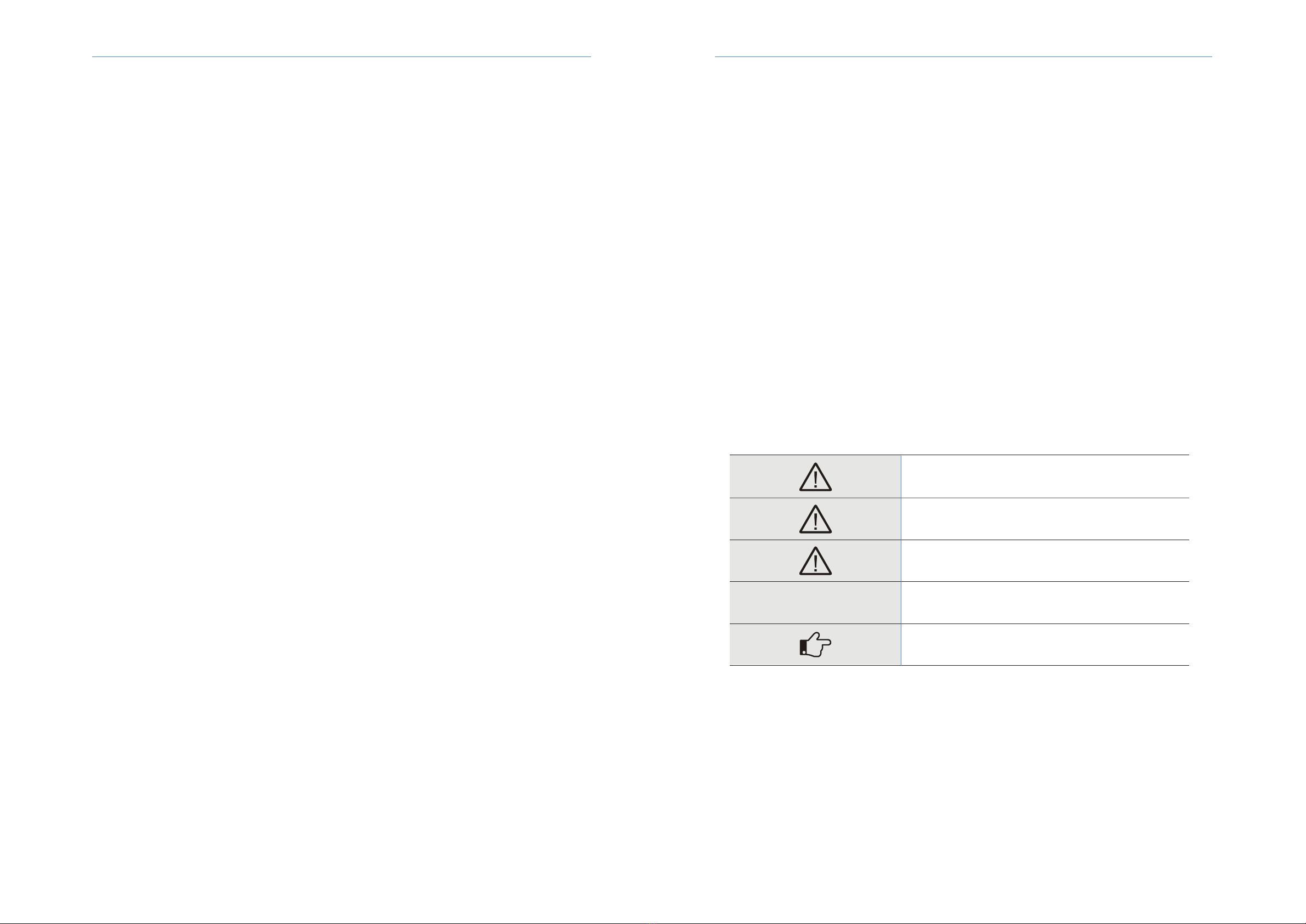
2.3 Explanation of symbols
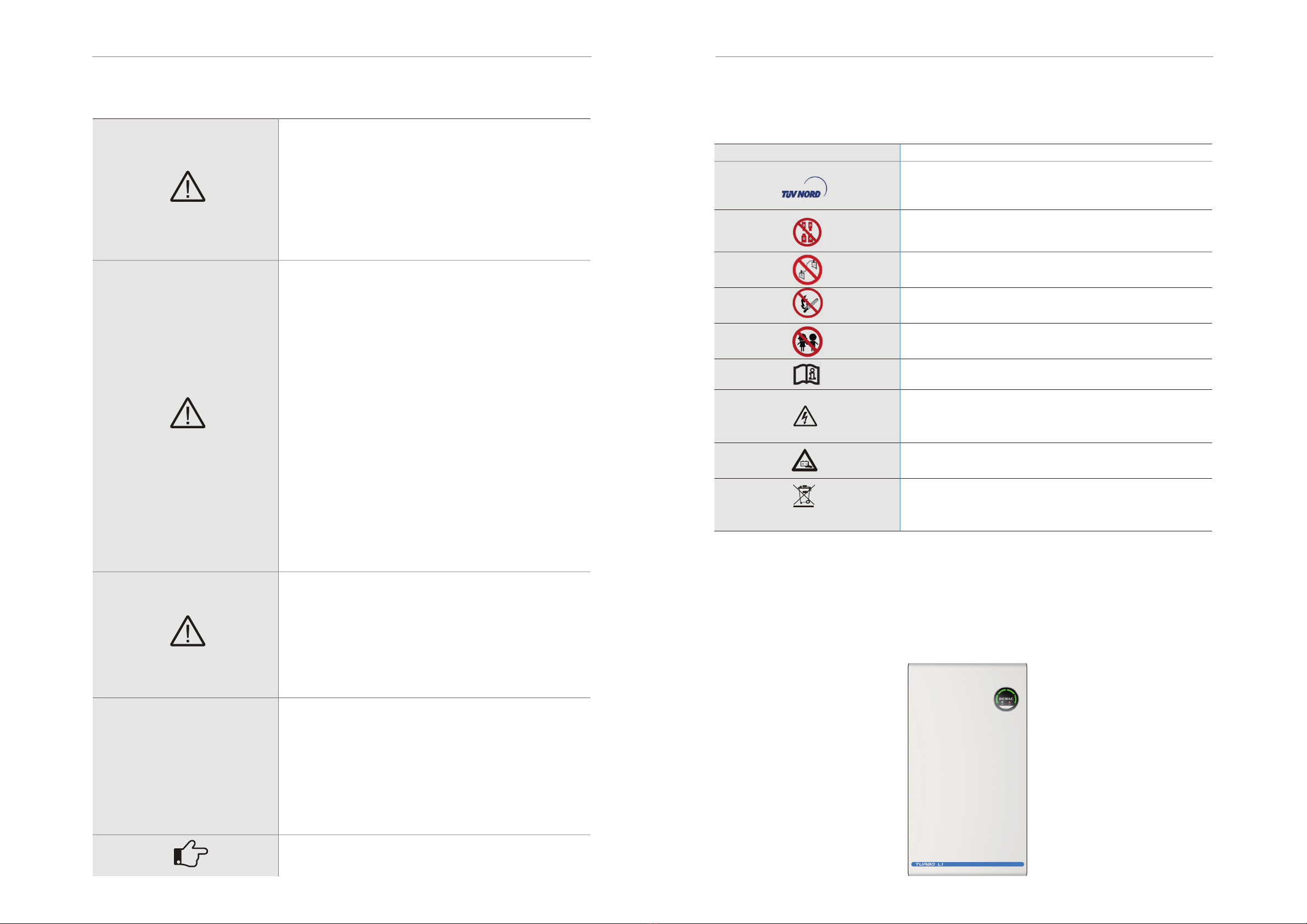
3. Introduction
3.1 Product Overview
This section gives an explanation of all the symbols shown on the type label.
Symbols on the type label
Do not disconnect or disassemble by untrained personnel.
TÜV NORD mark
Do not expose the battery to open flame, heat or sparks, as there is a risk of
fire or explosion.
Keep the battery modules away from children.
Observe the documents
Observe all documents supplied with the system.
Tha battery contains corrosive electrolytes.Please avoid contact with the
leaked substance.
WEEE designation
Do not dispose of the system together with the household waste but
in accordance with the disposal regulations for electronic waste
applicable at the installation site.
Warning! Metal parts of the batteries are always under voltage. Do not
short-circuit the batteries! In case of a short-circuit, may flow very high
currents and cause burns. By Touching conductive parts can cause cardiac
arrhythmia and shock.
Do not short circuit.
Symbol Explanation
DANGER!
◆Danger to life due to electric shock when live components or DC cables
are touched.
The DC cables connected to an inverter may be live. Touching live DC
cables results in death or serious injury due to electric shock.
Disconnect the battery system and inverter from voltage sources and
make sure it cannot be reconnected before working on the device.
Do not touch non-insulated parts or cables.
Do not remove the terminal block with the connected DC conductors from
the slot under load.
Wear suitable personal protective equipment for all work on the battery
system.
Observe all safety information of the inverter.
CAUTION!
◆Risk of injury due to weight of the battery module
Injuries may result if the battery module is lifted incorrectly or dropped
while being transported or installed.
• Transport and lift the battery module carefully. Take the weight of the
battery module into account.
• Wear suitable personal protective equipment for all work on the battery
system.
◆If the battery is not installed within one month after receiving the
battery,
the battery must be charged till the SOC is more than 50% for maintains.
NOTICE!
Firefighting Measures
The battery modules may catch fire when it is put into the fire. In case of a
fire, please make sure that an ABC or carbon dioxide extinguisher is
nearby. Water cannot be used to extinguish the fire.
Full protective clothing and self-contained breathing apparatus are
for the firefighters to extinguish the fire.
◆Damage to the battery system due to under voltages
If the battery system doesn't start at all, please contact Renac after-sales
service within 48 hours. Otherwise, the battery could be permanently
damaged.
NOTE!
◆Electrical installation and maintenance must be carried out by competent
electricians according to local regulations.
WARNING!
◆Battery Module Leakage
If the battery modules leak electrolytes, contact with the leaking liquid or
gas should be avoided. The electrolyte is corrosive, and the contact may
cause skin irritation and chemical burns. If one is exposed to the leaked
substance, do these actions:
Inhalation: Evacuate the contaminated area, and seek medical help
immediately.
Eye contact: Rinse eyes with flowing water for 15 minutes and seek
medical help immediately.
Skin contact: Wash the affected area thoroughly with soap and water and
seek medical help immediately.
Ingestion: Induce vomiting and seek medical help immediately .
◆The battery modules and its components should be protected from
damage when transporting and handling.
Do not impact, pull, drag, or step on the battery modules.
Do not insert unrelated objects into any part of the battery modules.
Do not throw the battery module into a fire.
Do not soak the battery modules in water or seawater.
Do not expose to strong oxidizers.
Do not short circuit the battery modules.
The battery modules cannot be stored at high temperatures (more than
50°C).
The battery modules cannot be stored directly under the sun.
The battery modules cannot be stored in a high humidity environment.
Do not use the battery modules if it is defective, or appears cracked,
broken or otherwise damaged,or fails to operate.
Do not attempt to open, disassemble, repair, tamper with, or modify the
battery modules. The battery modules are not user-serviceable.
Do not use cleaning solvents to clean the battery modules
NOTICE
2.2Important safety instructions
Turbo L1 Series User Manual 5Turbo L1 Series User Manual4