DANGER!
◆
are touched.
The DC cables connected to an inverter may be live. Touching live DC
Disconnect the battery system and inverter from voltage sources and
Do not touch non-insulated parts or cables.
the slot under load.
system.
Observe all safety information of the inverter.
CAUTION!
◆
while being transported or installed.
battery module into account.
system.
◆
battery,
the battery must be charged till the SOC is more than 50% for maintains.
NOTICE!
Full protective clothing and self-contained breathing apparatusare
◆Damage to the battery system due to under voltages
service within 48 hours. Otherwise, the battery could be permanently
damaged.
NOTE!
◆Electrical installation and maintenance must be carried out by competent
electricians according to local regulations.
WARNING!
◆
gas should be avoided. The electrolyte is corrosive, and the contact may
immediately.
medical help immediately.
◆The battery modules and its components should be protected from
damage when transporting and handling.
Do not impact, pull, drag, or step on the battery modules.
Do not insert unrelated objects into any part of the battery modules.
Do not short circuit the battery modules.
The battery modules cannot be stored at high temperatures (more than
50°C).
The battery modules cannot be stored directly under the sun.
The battery modules cannot be stored in a high humidity environment.
Do not attempt to open, disassemble, repair, tamper with, or modify the
battery modules. The battery modules are not user-serviceable.
Do not use cleaning solvents to clean the battery modules
NOTIC E
2.2Importantsafety instructions
Turbo H3 Series User Manual 5Turbo H3 Series User Manual4
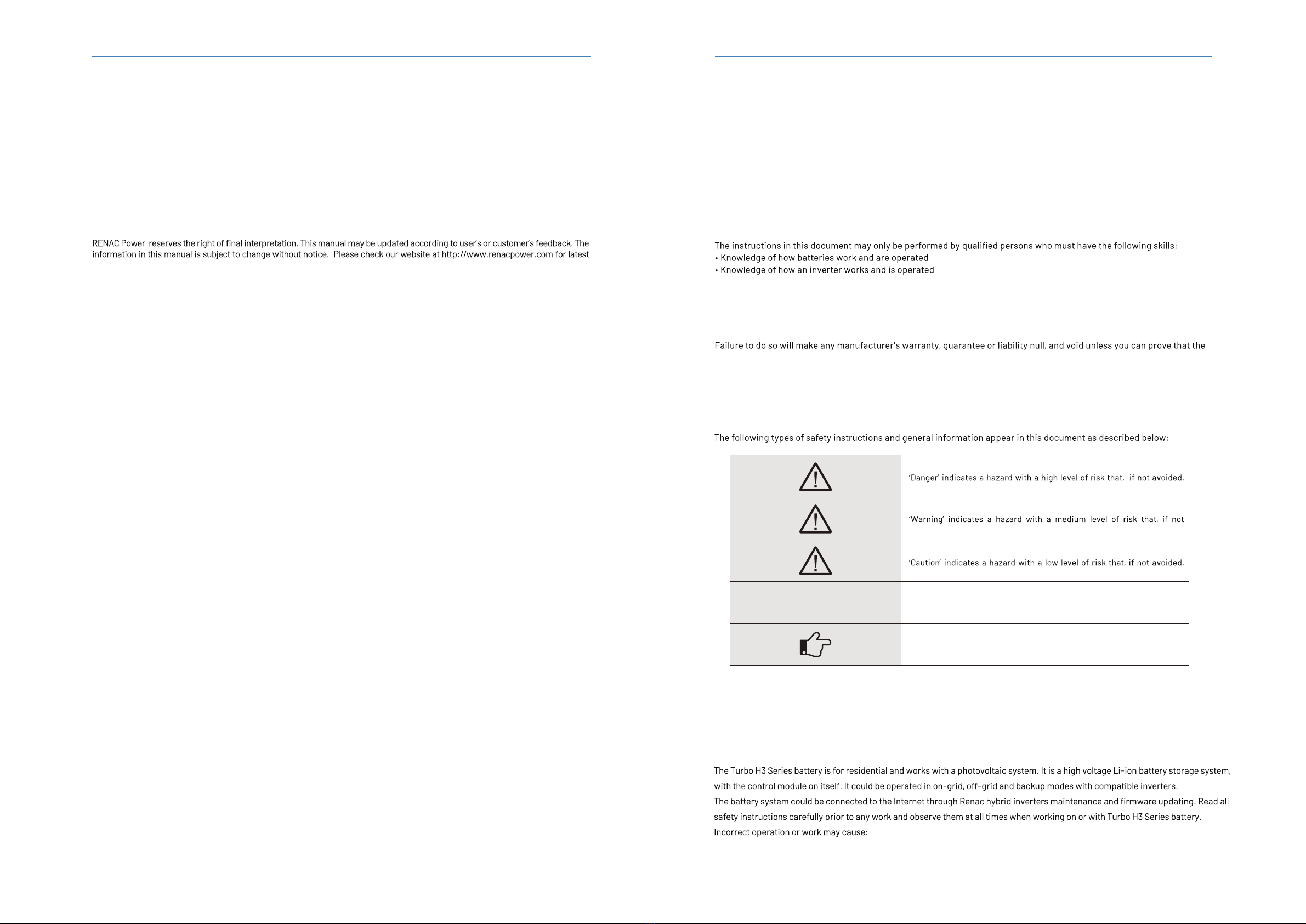
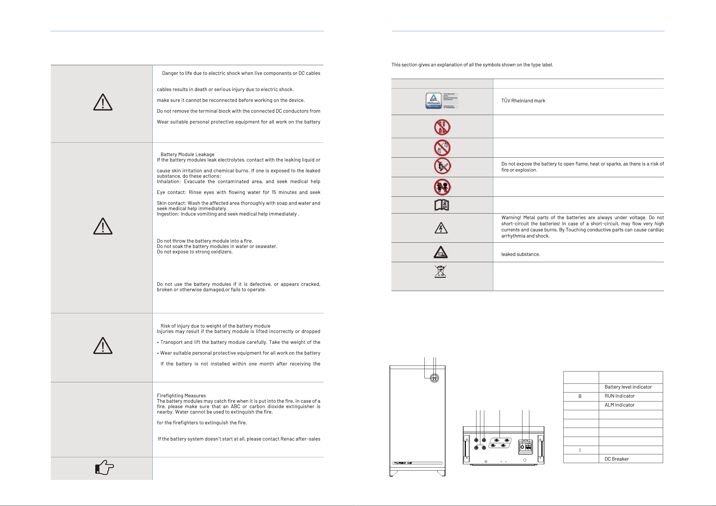
2.3 Explanation of symbols
3. Introduction
Symbols on the type label
Do not disconnect or disassemble by untrained personnel.
Keep the battery modules away from children.
Observe the documents
Observe all documents supplied with the system.
Tha battery contains corrosive electrolytes.Please avoid contact with the
WEEE designation
Do not dispose of the system together with the household waste but
in accordance with the disposal regulations for electronic waste
applicable at the installation site.
Do not short circuit.
Symbol Explanation
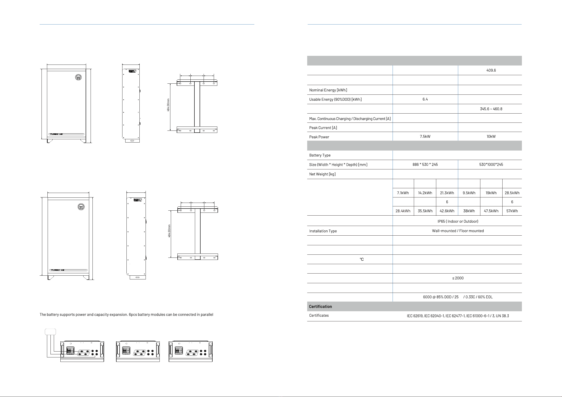
3.1 Product terminals
Object Description
A
C
D
E
F
H
J
CAN port
Parallel ports
RS485 port
Power terminals
Switch
A BC
DC Breaker
Switch
RS485
COM IN
CAN
JIH
F
E
D
BAT+
BAT-
+
-
-
+
COM OUT