H31764
Bulb
Switch
Fuse/fusible
link and rating
Item no.
Pump/motor
Earth and location
(via lead)
Resistor
Variable resistor
Diode
Internal connection
(connecting wires)
Gauge/meter
Wire splice or connector
Connections to other
circuits. Direction of
arrow denotes current
flow.
Solenoid actuator
Multiple contact
switch (ganged)
Wire colour
(Red wire/white tracer )
Denotes alternative wiring
variation (brackets)
Screened cable
Light emitting diode
(LED)
F24 30A
M
High beam
warning light
Diagram 3, Arrow A
A
R/W
{
15
F1 20A Cooling fan
F2 25A Horn
F3 15A RH main beam
F4 15A LH main beam
F5 10A Reversing light (automatic transmission)
F6 10A Clock/radio and memory units, electric mirrors, alarm
F7 25A Front wiper park position
F8 15A Direction indicators and hazard warning light
F9 25A Windscreen wiper
F10 15A Instrument panel, air bag, pretensioners, alarm, memory seats
F11 25A Central locking
F12 30A +ve supply after ignition switch
F13 5A Variable power steering
F14 5A ABS
F15 5A Automatic transmission
F16 15A RH dipped beam headlight
F17 15A LH dipped beam headlight, headlight levelling
F18 15A Stop lights, cruise control, flasher unit, bulb failure unit
F19 20A Heated seats
F20 20A Rear screen wiper, heated front/rear screen, reversing lights, lights on buzzer,
heater controls
F23 15A Variable shock absorbers
F24 10A Clock, display illunination, alarm, memory seats
F25 10A Rear fog light
F26 20A Radio, heater controls, cigar lighter
F27 25A Memory seats
F28 25A Front fog lights
F29 15A Boot and interior lights
F30 5A Injection
F31 10A Heated mirrors
F32 30A Sunroof
F33 5A Radio telephone
F34 10A LH side light, lights, bulb failure unit
F35 40A Heated rear screen
F37 40A Air conditioning
F38 40A Driver’s electric window
F39 40A Passenger’s electric window
F40 40A Power passenger seat
E1 Below RH rear light cluster
E2 Below LH rear light cluster
E3 Below LH rear light cluster
E4 RH driver’s inner sill
E5 LH passenger’s front inner sill
E6 LH passenger’s rear inner sill
E7 RH side engine (petrol)
LH side engine (Diesel)
E8 Front of engine compartment’
below LH headlight
Diagram 1 Information for wiring diagrams
Diagram 2 Starting, charging, Diesel fuel shut-off,
engine cooling fan,
Diagram 3 Diesel fuel heater, pre and post heating
Diagram 4 Turbo Diesel pre and post heating, ABS
Diagram 5 Automatic transmission, air bag/pretensioners,
variable power steering
Diagram 6 Fuel injection Bosch monopoint
Diagram 7 Fuel injection (Bendix Siemens MPi)
Diagram 8 Instrument cluster
Diagram 9 Instrument cluster
Diagram 10 Speed sensor, clock/external temperature gauge,
heater blower
Diagram 11 Heated front/rear screen, heated washer jets,
windscreen wash/wipe
Diagram 12 Rear wash/wipe, headlight washer, sidelights
and headlights
Diagram 13 Stop, reversing,fog and direction indicator lights
Diagram 14 Headlight levelling, interior lighting
Diagram 15 Rheostat interior lighting, audio system,
central locking
Diagram 16 Electric mirrors and windows
E1
Fuse Rating Circuit protected
15 Ignition switch 'ignition' position
15 Ignition switch 'ignition' position
30 Battery +ve
31 Earth
50 Ignition switch 'start' position
85 Relay winding input
86 Relay winding earth
87 Relay output
87a Relay output
D+ Charge warning light
Box shape denotes part
of a larger component
30 Terminal identification
(i.e. battery +ve)
A10 Connector pin number
30 A10
F51 60A Accessory cut-off shunt
F52 60A + battery passenger compartment
F53 60A + ignition switch
F54 60A After ignition relay
F55 40A RH cooling fan
F56 40A LH cooling fan
F57 30A ABS
F58 40A Headlight washers
F60 30/70A Fuel injection (30A), Diesel pre-heating (70A)
F65 70A Heated windscreen relay
Fuse Rating Circuit protected
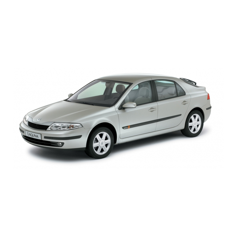
Diagram 1RENAULT LAGUNA wiring diagrams
Key to symbols Earth locations Key to circuits
Typical passenger compartment fuse box
Terminal identification
Typical engine compartment fuse box
