Renegade RXA 1000 D User manual

Please read the user‘s manual carefully before the installation and the rst operation
of the amplier.
SPECIFICATIONS RXA1000D
Output Power RMS
Output Power Max.
Loudspeaker impedance (stereo)
Frequency Response
Total Harmonic Distortion
Signal-to-Noise Ratio
Input Sensitivity
Input Impedance
Lowpass Filter
Subsonic Filter
Bass EQ
Line Outputs
Operating Voltage
Fuse Rating
Dimensions (B x H x L)
1 x 250 W @ 4 Ohms
1 x 500 W @ 2 Ohms
1 x 500 W @ 4 Ohms
1 x 1000 W @ 2 Ohms
2 – 8 Ohm
10 – 160 Hz (-3 dB)
< 0,5 % (80 Hz)
> 105 dB
0,2 – 5 V
10 kOhm
22 – 160 Hz Hz @ 12 dB/Octave
10 – 35 Hz @ 12 dB/Octave
0 – 12 dB @ 40 Hz
Stereo, fullrange
+12 V (9 – 15 V), negative ground
2 x 30 A
220 x 48 x 330 mm
All Specications are subject to change
WARRANTY
This product meets the current EU minimum warranty requirements, if purchased in countries of the EU. To en-
sureyourwarrantypolicykeepyouroriginalreceiptproongthedateofpurchase.Anydamagetotheproduct
as a result of misuse, abuse, accident, incorrect wiring, improper installation, alteration of date code or barcode
labels, revolution, natural disaster, or any sneaky stuff because someone messed up, repair or alteration out
side of our factory or authorized service centers and any thing else you have done that you should not have
doneisnotcovered.Thiswarrantyislimitedtodefectivepartsandspecicallyexcludesanyincidentalorcon-
sequential damages connected therewith.

IMPORTANT NOTES PRIOR TO INSTALLATION
- This device is only suited for a 12 volt system with negative ground.
-Theradiatedheatwhileoperationrequiressufficientaircirculationattheplaceofinstallation.Itis
veryimportantthattheheatsinkfinsdonothavecontactwithanymetalpartsoranysurfaceswhich
couldimpairaircirculation.Theamplifiermaynotbeinstalledinsmallclosedlocationorspaces
without air circulation (e.g. spare wheel recess or below the vehicle carpeting). We recommend the
installationinthevehicle’strunk.Ensuresufficientprotectionagainstvibrations,dustanddirt.
-Ensurethattheinputandoutputcablesaresufficientlyseparatedfromthepowersupplycables.
Otherwise interferences may occur.
- Ensure the accessibility of the fuse and the operating elements after installation.
-Thereliabilityandperformanceoftheamplifierdependsonthequalityofinstallation.Preferably
consult an expert to install the system, particularly if you want to install several loudspeakers.
POWER SUPPLY AND TURN-ON-CONNECTION
INTERCONNECTION
ATTENTION: Before you start with the installation, disconnect the ground connection from the vehicle’s
battery in order to prevent short circuits.
Thepowerwiringwhichisusuallyinstalledinon-boardcarnetworksisnotsufcientforapoweramplier‘s
demands.MakesurethatthepowerwirestoGNDandtothe+12Vterminalhasbeensufcientlyspecied.A
cable crosssection of at least 10 mm2mustbeusedtoconnectthebatterytotheamplier‘sterminals.
FirstconnecttheGNDterminaloftheampliertoanappropriategroundconnectionatthechassis.Toensurea
good connection, residue dirt and dust from the connection point. A loose connection may cause malfunctions
or interferences noise and distortion.
Then connect the +12 V terminal of the amplier with the battery by using an appropriate cable including
an in-line fuse. This fuse should be located very close to the battery; for safety reasons not more than 30
cm away. Only insert the fuse when the installation, including the connection of the loudspeakers, has been
accomplished.
Thenconnecttheremoteturn-on-wirefromtheheadunitwiththeamplier‘sREMOTEterminal.Acablewitha
cross-section of 0.5 mm2is adequate.
LOUDSPEAKER CONNECTIONS
- The total impedance must not be lower than 2 ohms.
- Never connect loudspeaker cables with the ground of the chassis or the +12 V supply voltage.
Iftheamplierisoperatedwithatoolowimpedanceorincorrectlyused,theentiresoundsystem
may be damaged. This means a warranty void in such cases.

AUDIO SIGNAL CABLES
WheninstallingtheaudiocablesbetweentheRCAoutputsoftheheadunitandtheRCAinputsoftheamplier,
the audio and power supply cables should, if possible, not be routed along the same side of the vehicle. We
recommend a separated installation, e.g. routing the power cable through the cable channel on the left side
and the audio cables through the cable channel of the vehicle on the right side or vice versa. This prevents
interferences due to crosstalk into the audio signal.
SIGNAL OUTPUTS TO CONNECT ADDITIONAL AMPLIFIERS
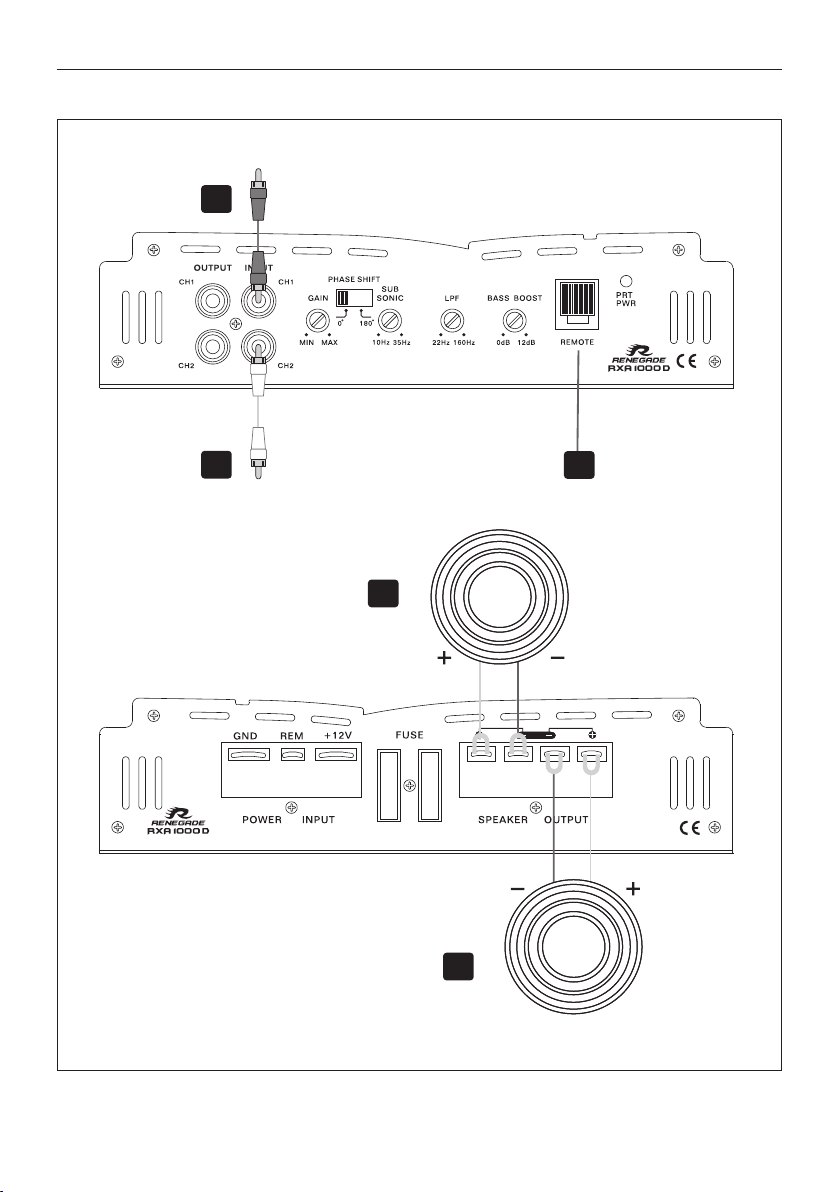
The input signal on the INPUT jacks (Fig. 1,2) will be routed in stereo to the output jacks OUTPUT (Fig. 1,1).
ThustheOUTPUTjackallowstheconnectionofaadditionalamplifier.
OPERATING ELEMENTS
INPUT SENSITIVITY
TurntheGAIN(Fig.1,3controlleroftheampliertotheMINposition.Thenturnthevolumecontrollerofthe
headunit to 80 - 90% of its full setting. Now turn GAIN clockwise until you hear some distortion. Then turn back
the GAIN slightly until you hear a cleaner sound.
VARIABLE SUBSONIC FILTER
WiththeSUBSONICcontroller(Fig.1,5youcanadjustthelowercross-overfrequency,toltertheverylow
frequencies to relieve the subwoofer or to generate a bandpass signal. If you don’t want to use this function,
turn the controller (Fig. 1,5) to the very left to the 10 Hz position.
NOTE: The adjusted value of the SUB SONIC (Fig. 1,5) should not be higher than the adjusted value of the
LPF controller (Fig. 1,6). Otherwise no sound will be hearable.
VARIABLE LOW PASS FILTER
Set the desired cross-over frequency by using the controller LPF (Fig. 1,6). Thus to that only the frequencies
belowthechosencross-overfrequencywillbeampliedandthesubwooferplaysmoreprecisedandefcient.
PHASE SHIFT SWITCH
The PHASE SHIFT switch (Fig. 1,4) allows to set the phase between 0° or 180° to match the run time of the
output signal with the vehicle’s interior acoustic.
VARIABLE BASS BOOST
With the bass boost controller (Fig.1,7) you are able to adjust the bass level from 0 - 12 dB.
Attention: Use the BASS BOOST wisely!
BASS LEVEL REMOTE CONTROLLER
With the included bass level cable remote controller you are able to adjust the bass level e.g. out of the driver’s
seat.
PROTECTION CIRCUIT
ThePOWER-LED(Fig.1,9litsup,iftheamplierisinoperation.
ThePROTECT-LED(Fig.1,9litsup,whentheamplierisoverheated,orashortcircuitoccursresp.atoolow
impedance load is connected to the speaker outputs. If this events, the internal built-in protection circuit shuts
downtheamplierautomatically.Theampliershouldworkagainproperlyafteryouhavesolvedtheproblems.

FIGURES (P. 28-30)
CONNECTIONS AND CONTROLLERS (FIG. 1)
(1) Audiosignaloutputstorunadditionalampliers
(2) Audio signal inputs
(3) Gain level controller
(4) Phase Shift switch
(5) Subsonicltercontroller
(6) Lowpassltercontroller
(7) Bass Boost controller
(8) Connector for the included bass level remote controller
(9) Power-/Protection-LED
POWER SUPPLY AND TURN ON CONNECTION (FIG. 2)
(1) GND terminal for the ground
(2) REM terminal for the turn on connection
(3) +12 V terminal for the positive-connection of the battery
(4) Vehicle’s battery
(5) In-Line Fuse (not included in the scope of delivery)
(6) Turn on wire from the headunit or the electrical antenna
(7) Fuse
1-CHANNEL OPERATION MONO 2 SUBWOOFERS (FIG. 4)
Ifyou want to runthe amplier withthe 2 line outputchannels from theheadunitto drive twosubwoofers,
connect the following setup:
(1) To the headunit, line output rear left or subwoofer output
(2) To the headunit, line output rear right or subwoofer output
(3) Bass level remote controller
(4) Subwoofer1(4-8Ω)
(5) Subwoofer2(4-8Ω)
1-CHANNEL OPERATION MONO 1 SUBWOOFER (FIG. 3)
Ifyouwanttoruntheamplierwiththe2lineoutputchannelsfromtheheadunittodriveasubwoofer,connect
the following setup:
(1) To the headunit, line output left or subwoofer output
(2) To the headunit, line output right or subwoofer output
(3) Bass level remote controller
(4) Subwoofer(2-8Ω)
IMPORTANT!
Always observe the correct polarity of all connections!

TROUBLESHOOTING
If you are having problems after installation follow the Troubleshooting procedures below.
Procedure 1:
CheckAmplierforproperconnections.
Verify that PRT/PWR LED lits up green. If If this is the case, skip to Step 3, if not continue.
1. Check in-line fuse on battery positive cable. Replace if necessary.
2. Checkfuse(s)onamplier.Replaceifnecessary.
3. Verify that Ground connection is connected to clean metal on the vehicle’s chassis. Repair/replace if necessary.
4. Verify there is 9 to 16 Volts present at the positive battery and remote turn-on cable.Verify quality connections for both cables at
amplier,stereo,andbattery/fuseholder.Repair/replaceifnecessary.
Procedure 2:
PRT/PWR LED lits up red.
1. If the PROTECT lits up red, this is a sign of a possible short in the speaker connections. Check for proper speaker connections
and use an ohm meter to check for possible shorts in the speaker wiring. Too low speaker impedance may also cause PROTECTION
tolight.ThiscanalsobeasignofdrivingtheamplieratveryhighpowerGAINswithoutadequateairowaroundtheamplier.Shut
offthesystemandallowampliertocool.Checkthatthevehiclechargingsystemismaintainingpropervoltage.Ifthepreviousitems
donotsolvetheproblem,afaultmaybeintheamplier.Inthiscaseyoushouldcontactyourdealer.
Procedure 3:
CheckAmplierforaudiooutput.
1. VerifygoodRCAinputconnectionsatstereoandamplier.Checkentirelengthofcablesforkinks,splices,etc.
Test RCA inputs for AC volts with stereo on. Repair/replace if necessary.
Procedure 4:
CheckAmplierforapoppingnoisewhileturningon.
1.Disconnectinputsignaltoamplierandturnamplieronandoff.
2.Ifthenoiseiseliminated,connecttheREMOTEleadofampliertosourceunitwithadelayturn-onmodule.
Procedure 5:
CheckAmplierifyouexperienceexcessEngineNoise.
1. Route all signal carrying wires (RCA, Speaker cables) away from power and ground wires.
OR
2. Bypassanyandallelectricalcomponentsbetweentheheadunitandtheamplier(s).Connectstereo
directlytoinputofamplier.Ifnoisegoesawaytheunitbeingbypassedisthecauseofthenoise.
OR
3. Remove existing ground wires for all electrical components. Reground wires to different locations.
Verify that grounding location is clean, shiny metal free of paint, rust etc.
OR
4. Add secondary ground cable from negative battery terminal to the chassis metal or engine block of vehicle.
OR
5. Have alternator and battery load tested by your mechanic.Verify good working order of vehicle electrical system including distributor,
spark plugs, spark plug wires, voltage regulator etc.

3
1
2
2 - 8 Ω
4
3

4 - 8 Ω
5
4 - 8 Ω
4
4
1
23
Table of contents
Other Renegade Amplifier manuals

Renegade
Renegade REN10KIT User manual

Renegade
Renegade RXA 1200 D User manual

Renegade
Renegade RXA 1100 User manual

Renegade
Renegade REN10KIT User manual

Renegade
Renegade ren 1100s mk3 User manual

Renegade
Renegade RXA1500 User manual

Renegade
Renegade RXA 1100 User manual

Renegade
Renegade REN 380 User manual

Renegade
Renegade REN1000S Mk3 User manual

Renegade
Renegade RXA 550 User manual