Renegade RX1200 User manual

RX 1200
1.2 FARAD POWERCAP
BEDIENUNGSANLEITUNG
OWNER’S MANUAL
MANUEL D’INSTALLATION

2
Inhaltsverzeichnis Seite
Verwendungsmöglichkeiten 3
Sicherheitshinweise 4
Montage 5
Erstes Aufladen 5
Anschlussbeispiele 6
Funktionsbeschreibung 7
Entladen 8
Justierung der Voltanzeige 8
Nenn-Kapazität: 1.2 Farad
Dauer-Betriebsspannung: 12 ~ 16V DC
Maximale Betriebsspannung: 18V DC max.
Betriebstemperatur: –20 ~ + 60° C
Abmessungen (ohne Montagehalter): 260 x ø74 mm
BEDIENUNGSANLEITUNG
TECHNISCHE DATEN
1 Pufferkondensator
2 Montagehalter
1 Lade-/Entlade-Lampe
1 Bedienungsanleitung
Einbauzubehör
LIEFERUMFANG
Technische Änderungen vorbehalten!
DEU

3
VERWENDUNGSMÖGLICHKEITEN
Der Pufferkondensator wird in Kraftfahrzeugen zur Stabilisierung und
Unterstützung der Stromversorgung eines Verstärkers eingesetzt, wenn dieser
schnell und für kurze Zeit hohe Ströme benötigt. Er kann kurzfristige Belastungen
der Bordspannungen bei z.B. besonders tiefen, kräftigen Bässen ausgleichen.
Durch die Verwendung des Pufferkondensators ergibt sich eine wesentlich
bessere Leistungsentfaltung des Verstärkers.
Car Audio Verstärker benötigen für den optimalen Betrieb hohe Stromstärken.
Herkömmliche Fahrzeugbatterien sind normalerweise nicht für die zusätzliche
Versorgung eines Verstärkers ausgelegt.
Ein weiterer Vorteil des Pufferkondensators ist das Filtern von Wechsel-
spannungen, die im Netzteil des Verstärkers indiziert werden. Ungefilterte
Wechselspannungen können hörbare Interferenzen verursachen.
Bassleistung bei 50Hz und 70Hz
ohne Pufferkondensator Bassleistung bei 50Hz und 70Hz
mit Pufferkondensator
DEU

4
SICHERHEITSHINWEISE
Bevor Sie mit der Installation des Kondensators beginnen, sollten Sie die
folgenden Anweisungen der Bedienungsanleitung genau befolgen!
Andernfalls besteht Verletzungsgefahr oder das Gerät könnte ernsthaft
beschädigt werden.
Der Pufferkondensator entspricht der KFZ-Richtlinie für den Betrieb in Fahrzeugen
innerhalb der Europäischen Union und besitzt eine E-Zertifizierung als auch
eine CE-Kennzeichnung (Konformitätserklärung).
Der Anschluss des Pufferkondensators an das 12 V-Bordnetz darf nur durch
qualifiziertes Fachpersonal erfolgen. Dabei ist besondere Sorgfalt geboten. Bei
Kurzschlüssen können gefährlich hohe Ströme fließen.
Der Pufferkondensator speichert sehr hohe Stromreserven und könnte bei
falscher Handhabung sogar explodieren. Wird der Kondensator zweckentfremdet,
nicht richtig angeschlossen oder nicht fachgerecht repariert, können Sach- oder
Personenschäden daraus resultieren.
Der Kondensator muss fest und fachgerecht an einer mechanisch stabilen Stelle
montiert werden.
Auf keinen Fall darf der Pufferkondensator mit einer höheren Spannung als
18 Volt betrieben werden oder ein Kurzschluss an den Strom-Anschlussklemmen
verursacht werden.
Schützen Sie den Kondensator vor Feuchtigkeit und Hitze (zulässiger
Einsatztemperaturbereich -20 °C bis +60 °C).
Für die Reinigung nur ein weiches, trockenes Tuch verwenden, auf keinen Fall
Chemikalien oder Wasser.
VORSICHT
ELEKTROSCHOCK
DEU

5
MONTAGE
Für bestmögliche Ergebnisse sollte der Kondensator so nahe wie möglich bei
der Endstufe installiert werden. Die Kabel zwischen dem Kondensator und der
Endstufe sollten möglichst kurz sein und einen möglichst großen Querschnitt
aufweisen. Die Kabel sind so zu verlegen, dass deren Isolierung während des
Einbaus und des Betriebes nicht beschädigt werden.
1.) Verwenden Sie die beiliegenden Halter um den Kondensator an einer
mechanisch stabilen Stelle fest anzuschrauben. Montieren Sie das Gerät
keinesfalls auf stark vibrierenden Flächen wie beispielsweise einem Gehäuse-
subwoofer.
2.) Der korrekte Anschluss ist auf der nächsten Seite dargestellt. Zur Vermeidung
von Störgeräuschen sollte der Masseanschluss des Kondensator an der gleichen
Stelle erfolgen, an der auch der Verstärker angeschlossen wird.
ERSTES AUFLADEN
Beim erstmaligen Aufladen des Kondensators sollte unbedingt die beiliegende
Lade-/Entlade-Lampe benutzt werden um den Ladestrom zu begrenzen und
Anschlussfunken zu vermeiden. Verbinden Sie dabei das Massekabel „-” mit
dem „-” Anschluss des Kondensators. Dann klemmen Sie die beigelegten Lampe
an den „+“ Anschluss des Kondensators und halten das „+“ Kabel des
Batterieanschlusses bzw. des Verteilerblocks an das andere Ende der Lampe.
Die Lampe kann nach ca. einer Minute oder wenn der Kondensator ca. 10 Volt
erreicht hat entfernt werden. Schließen Sie nun das „+“ Kabel der Batterie an
den „+“ Anschluss des Kondensators an, um den Ladevorgang bis zu 12~14V
abzuschließen.
Währendes des Ladeprozesses zwischen 5 ~ 10 Volt blinkt das Display!
Die Lade-/Entladelampe könnte während des Ladens sehr heiß werden.
Achten Sie unbedingt darauf, die Terminals nicht kurzzuschließen!
Batterie-
anschluss Masse-
anschluss
Lampe
10.00
DEU

Verstärker
6
ANSCHLUSSBEISPIELE
Anschluss mit Verteilerblock (empfohlen)
Sicherung
Anschluss ohne Verteilerblock
Sicherung
Hinweis:
Achten Sie auf korrekte Polung!
Verteilerblock
Batt.
Hinweis:
Achten Sie auf korrekte Polung!
Verstärker
Batt.
DEU

FUNKTIONSBESCHREIBUNG
Digital Voltanzeige
Diese Anzeige zeigt die aktuelle Betriebsspannung in Volt an und ist somit
eines der wichtigsten Features zur Statusanzeige der Stromversorgung des
Fahrzeuges.
Während des Aufladens (5 ~ 10 Volt) oder wenn die anliegende Spannung
unter 10 Volt fällt, beginnt das Display zu blinken.
Die beiden Status-LEDs leuchten solbald sich das Display einschaltet und
haben darüber hinaus keine weitere Funktion.
Warnton
Wenn ein Vertauschen der Pole (+und –Anschluss) vorliegt, ertönt sofort ein
Warnton.
Entfernen Sie in diesem Fall sofort die Anschlüsse. Explosionsgefahr!
Potentiometer
Dieser Regler erlaubt die Justierung der Voltanzeige.Mehr Informationen dazu
auf Seite 8.
Autoremote
Der Kondensator ist mit einer automatischen Aus- und Einschaltfunktion
ausgestattet. Solbald der Kondensator eine Spannungsschwankung bemerkt,
schaltet er sich von selbst ein und schaltet sich wieder von selbst aus, wenn
ca. zwei Minuten keine Schwankung bzw. Aktivität bemerkt wurde.
Potentiometer
Digitale Voltanzeige
Batterie-
anschluss Masse-
anschluss
7
Status-LEDStatus-LED
DEU

8
ENTLADEN
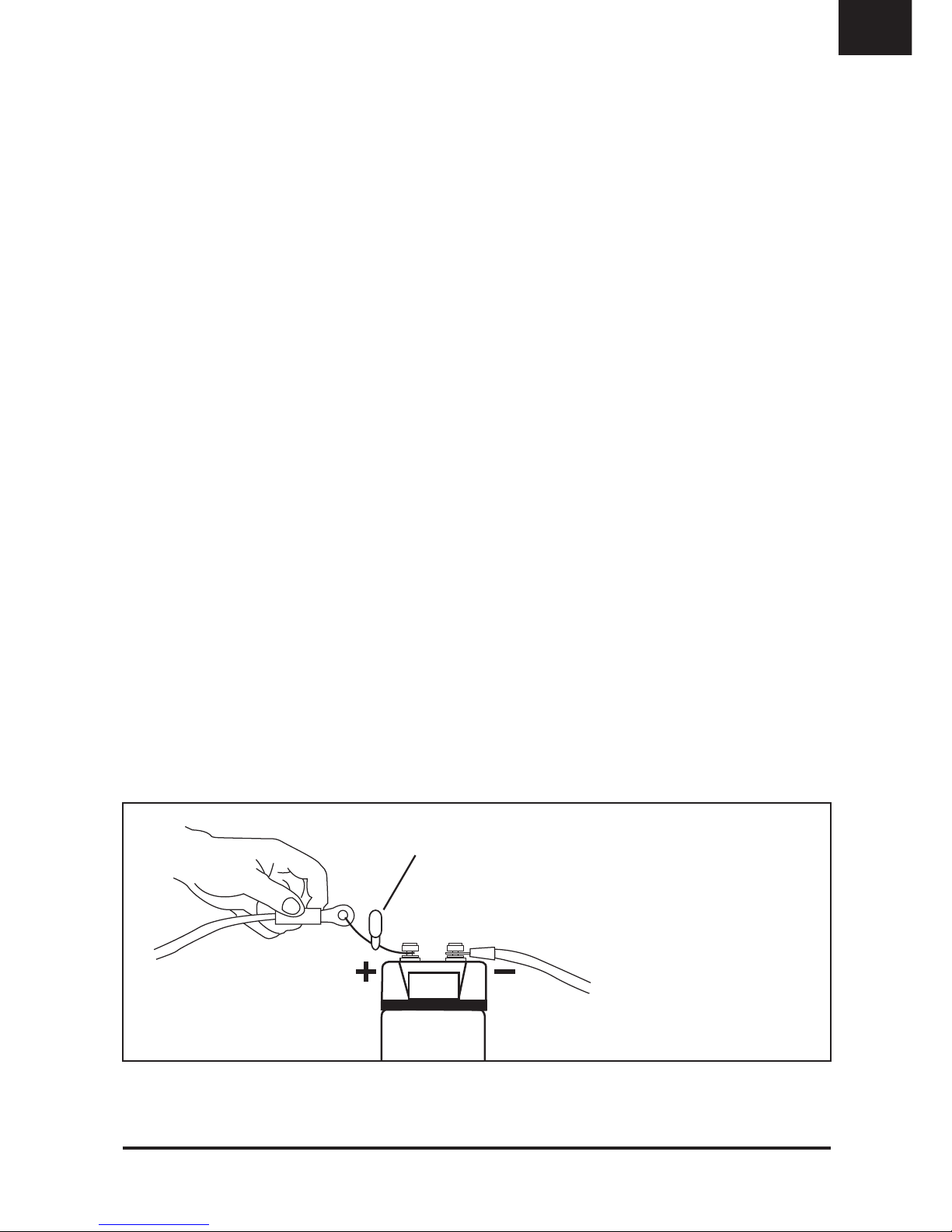
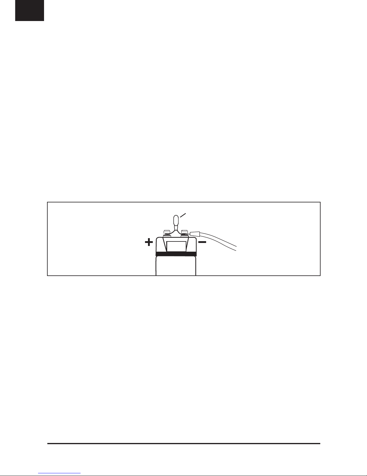
Wenn der Kondensator ausgebaut werden sollte, muss dieser aus Sicher-
heitsgründen komplett entladen werden. Zum Entladen des Kondensators
entfernen Sie das Kabel am „+“ Anschluss des Kondensator. Den „-“ Anschluss
lassen Sie noch an Masse angeschlossen. Verbinden Sie die mitgelieferte
Lade-/Entlade-Lampe mit dem „+“ und „-“ Pol.
Der Entladevorgang kann einige Minuten in Anspruch nehmen.
Es ist empfehlenswert, gegebenenfalls die Lampe während des Vorganges mit
einer Zange zu halten, da diese sehr heiß werden kann.
Beim Entladen beginnt das Display zu blinken und zeigt ”0.00” an, wenn die
Spannung unter 10 Volt fällt.
Erst wenn die Lampe nicht mehr leuchtet, ist das Entladen beendet.
Entladen Sie den Kondensator niemals ohne die beigelegte Lade-/Entlade-
Lampe!
Entladen Sie den Kondensator unter keinen Umständen durch
Kurzschließen der Terminals. Der Kondensator könnte dadurch beschädigt
werden oder explodieren.
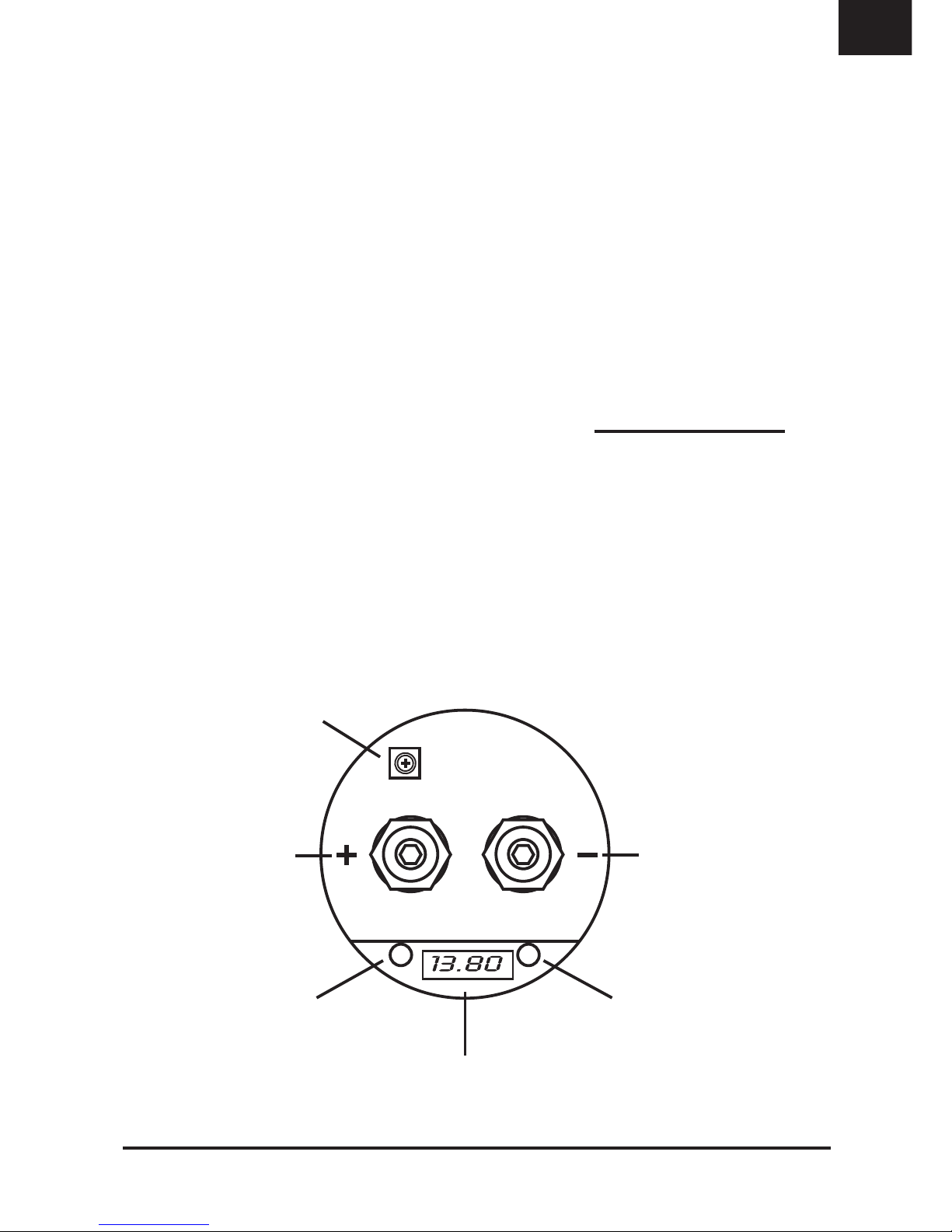
JUSTIERUNG DER VOLTANZEIGE
Die Justierung der Voltanzeige ist schon ab Werk erfolgt und kann bei Bedarf
nachjustiert werden. Bei der Installation weiterer Kondensatoren können durch
Toleranzen die Anzeigewerte variieren. Dies kann mit dem Potentiometer
nachjustiert werden.
Gehen Sie dabei wie folgt vor:
1.) Messen Sie die aktuelle Betriebsspannung am “+“ und “-“ Pol des Kondensators
mithilfe eines geeigneten Multimeters.
2.) Entfernen Sie dann vorsichtig die Acrylglas-Abdeckung oben am Kondensator
und stellen den Wert am Potentiometer (blaues, eckiges Bauteil) mit einem
geeignetem Schraubendreher auf den Wert, der zuvor gemessen wurde.
3.) Achten Sie unbedingt bei der Demontage darauf, die Anschlussklemmen
nicht kurzzuschließen.
4.) Oder beauftragen Sie Ihren Fachhändler.
Lampe
10.00
Batterie-
anschluss Masse-
anschluss
DEU

OWNER’S MANUAL
9
Content Page
Applications 10
Safety Instructions 11
Installation 12
Initial Charging Process 12
Wiring Diagram 13
Functional Descriptions 14
Discharging Process 15
Voltmeter Adjustment 15
Rated Capacity: 1.2 Farad
Continuous Voltage: 12 ~ 16V DC
Maximum Voltage: 18V DC max.
Operation temperature: –20 ~ + 60° C
Dimensions (without Mounting Brackets): 260 x ø74 mm
SPECIFICATIONS
1 Power Capacitor
2 Mounting Brackets (top and bottom)
1 Charging/discharging light bulb
1 Owner’s Manual
Installation Hardware
KIT INCLUDED
All specifications are subject to change without notice!
ENG

10
APPLICATIONS
The power capacitor is used in vehicles for stabilizing the 12 Volt supply and
support for car audio amplifiers, if fast and temporary high currents are required.
The power capacitor can compensate short-term power peaks on the on-board
electrical system for low and powerful bass operations.
The use of the power capacitors results in a considerably improved power
expansion of the amplifier.
Car audio amplifiers require very high current peaks for a proper operation.
Conventional car battery are not designed to deliver additional power supply
to car audio amplfiers.
Another feature of this power capacitor is to filter car AC voltage included by
the amplifier’s power supply. This can cause audible interferences in the audio
signal.
Bassperformance at 50Hz and 70Hz
without capacitor Bassperformance at 50Hz and 70Hz
with capacitor
ENG

11
SAFETY INSTRUCTIONS
Before you begin with the installation, please attend the following advices
in this manual. Otherwise the risk of injury or a damage of the device
consists.
The power capacitor is equivalent to common directives to be operated in
vehicles inside the European Union and owns a E-mark certification also as a
CE-mark.
The capacitor should be installed by qualified and skilled personnel only. Special
carefulness is essential, because in case of short circuits hazardous high currents
could occur.
The power capacitor stores an extremly large amount of electricity and may
explode or cause serious injury. If the device is used for other purposes than
originally intented or if not proper used or installed, personal injury or material
damage could occur.
The capacitor should be mounted at a mechanically stable position in the vehicle.
The device should be fixed properly and professional.
At no time the power capacitor should be exposed to voltages higher than
specified (max. 18 Volts) or its terminals shorted directly.
Protect the capacitor against humidity and heat (admissable temperature range
- 20 °C to +60 °C).
For cleaning use a dry and soft cleaning tissue, by no means any chemicals
or water.
WARNING!
ELECTRICAL
HAZARD
ENG

12
INSTALLATION
For achieving the best results the capacitor should be located close-by the
amplifier. The cables between capacitor and amplifier should be short as possible
and should have large cross section. While installing the cables or the operation,
ensure not to damage the insulation of the cables.
1.) Tightly screw the device with the supplied brackets and screws as close as
possible to the amplifier on a machanically stable position. By no means install
the capacitor on any kind of speaker enclosure or on high vibrating positions.
2.) The correct wiring is displayed on the next page. To avoid any interferences,
connect the capacitor’s ground connection at the same ground terminal like the
amplifier.
INITIAL CHARGING PROCESS
For the first initial charging use by any means the supplied light bulb, to limit
the charge current and to avoid connecting sparks. Connect the ”–” ground wire
with the ”–” terminal of the capacitor.
Then clamp the supplied light bulb to the ”+” terminal of the capacitor and hold
the ”+” wire of the battery or distribution block at the other end of the light bulb.
The light bulb can be disconnected after approx. one minute or if the capacitor
reached a load of 10 volts. Then connect the “+” terminal of the battery with the
“+” terminal of the capacitor to complete the charging process until 12~14 volts
are achieved.
During the charging process (5 ~ 10 Volt) the display starts flashing!
The light bulb may get very hot during the charging process.
Please avoid any short circuit on the terminals.
Battery
Terminal Ground
Terminal
Light bulb
10.00
ENG

13
WIRING DIAGRAM
Wiring with Distribution Block (recommended)
Wiring without Distribution Block
Batt.
Amplifier
Amplifier
Fuse
Fuse
Note:
Ensure correct polarity!
DIstribution
Block
Batt.
Note:
Ensure correct polarity!
ENG

14
FUNCTIONAL DESCRIPTIONS
Digital Voltmeter
This display indicates the actual operating voltage and is one of the most
important features to display the status of the car’s power supply.
During the charging process (5 ~ 10 Volts) or if the voltage drops below
10 Volts, the display starts flashing.
The both Status-LEDs start to glow as soon as the display is on, beyond that
they have no other function.
Audio Warning
If a interchange of the poles is occured, an audio warning is hearable.
In this case all disconnect all connections directly. Danger of Explosion!
Potentiometer
This controller allows to adjust the voltmeter.
Attend the information on Page 15.
Autoremote
The powercap is equipped with an autoremote function. If the powercap detects
any fluctation of the connected voltage, it turns automatically on. The powercap
turns off after approx. two minutes, when no fluctation or activity is detected.
Potentiometer
Digital Voltmeter
Battery
terminal Ground
terminal
Status-LEDStatus-LED
ENG

15
DISCHARGING PROCESS
If the capacior will be de-installated you need to discharge it completely. To
discharge the capacitor, remove the wire at the ”+” terminal of the capacitor.
Keep the ground terminal “-” connected. Then bridgeover the ”-”pole and ”+”pole
of the capacitor with the supplied light bulb.
The discharging process could last some minutes.
It is recommended to use a gripper during this procedure, because the light
bulb may get very hot.
The Display is flashing and shows ”0.00” during the discharging when the voltage
drops below 10 Volts. If the light bulb stops flashing, the discharging process
is accomplished.
Never discharge the capacitor without the supplied light bulb.
Never discharge the capacitor with bypassing the terminals (short circuit).
The capacitor may get damaged or explode.
VOLTMETER ADJUSTMENT
The adjustment is already done by the factory, but can be redone if necessary.
By using additional capacitors, various indicated values could be occured. This
can be adjusted by the potentiometer.
Follow these instructions:
1.) Measure the actual operating voltage on the ”+” und ”–”pole of the capacitor
by using an appropriate multimeter.
2.) Remove the acrylic-cover of the capacitor and adjust the value with the
potetiometer (little blue box) by using a appropriate screwdriver to the same
value, you have measured before.
3.) Ensure while removing the cover, not to short the terminals.
4.) Or assign your car audio retailer.
Light bulb
10.00
Battery
Terminal Ground
Terminal
ENG

MANUEL D’INSTALLATION
16
Sommaire Page
A quoi ca sert 17
Instructions de sécurite 18
Installation 19
Processus de charge initial 19
Schéma de cablâge 20
Descriptions de fonctions 21
Processus de décharge 22
Reglage du voltmétre 22
Capacité nominale: 1.2 Farad
Voltage continue: 12 ~ 16V DC
Voltage maximale: 18V DC max.
Température de fonctionnement: –20 ~ + 60° C
Dimension (sans crochet): 260 x ø74 mm
SPÉCIFICATIONS
1 Capacité de puissance
2 Crochet (haut et bas)
1 Ampoule
1 Manuel d’installation
Matériel d'installation
CONTENU DE LA LIVRAISON
Changements réservés!
FRA

FRA
17
A QUOI CA CERT?
La capacité de puissance est utilisée dans un véhicule pour stabiliser
l’alimentation 12V et pour assister les amplificateurs, si une demande de
courant rapide et brève est requisse. La capacité de puissance peut
compenser les demandes de puissance très brèves demandées lors
d’écoute de basses profondes et puissantes.
L’utilisation d’une capacité de puissance améliore très sérieusement la
puissance disponible à l’amplificateur.
Les amplificateurs audio provoquent des pics de courant très importants.
Une batterie de voiture conventionnelle n’est pas prévue pour répondre à de
telles sollicitations.
Un autre avantage de la capacité est sa fonction de filtrage de courant,
courant qui non filtré peut quelques fois provoquer des parasites.
Restitution sonore à 50Hz et 70Hz
sans capacité Restitution sonore à 50Hz et 70Hz
avec capacité

18
INSTRUCTIONS DE SÉCURITE
Avant de commencer votre installation, merci de lire attentivement ce
manuel. Cela vous évitera de prendre des risques et une détérioration
éventuelle de votre installation.
Cette capacité de puissance suit les directives concernant l’installation dans un
véhicule dans la communauté Européenne, elle détient la certification E-number
et aussi CE.
Cette capacité doit exclusivement être installée par un personnel qualifié. Une
attention toute particulière doit être portée, en cas de court-circuit un très fort
courant est en jeu !
La capacité de puissance stocke une très grande quantité d’électricité et peut
exploser ou provoquer des blessures. Si ce produit est mis en oeuvre pour une
autre utilisation que sa destination originelle ou s’il n’est pas proprement utilisé
ou installé, cela peut entrainer des blessures corporelles ou des dommages
matériels.
La capacité doit être installée dans un endroit stable dans le véhicule. Le produit
doit être fixé proprement et de façon professionelle.
A aucun moment la capacité ne doit être exposée à une tension supérieure à
celle spécifiée (max. 18 V) ou les deux bornes mises en contact.
Protégez la capacité de l’humidité et de la chaleur (température admissible de
-20° à +60°C).
Pour le nettoyage, utilisez un tissus doux et sec, évitez tout
produit chimique ou eau.
AVERTISSEMENT!
ÉLECTROCHOC
FRA

19
INSTALLATION
Pour obtenir le maximum de résultat, la capacité doit être installée le plus
près possible de l’amplificateur. Les câbles entre la capacité et l’amplificateur
doivent être le plus court possible et doivent avoir une grosse section. Bien
s’assurer pendant l’installation des câbles qu’aucun
des isolants ne soit abimé.
1.) Serrez fermement les vis servant à fixer la capacité avec les supports
spécifiques livrés avec le produit. N’oubliez pas d’installer la capacité le plus
près possible de l’amplificateur et sur une surface stable, cela implique d’éviter
la fixation sur une des faces d’un caisson ou sur une surface où est fixé un
haut-parleur.
2.) Le bon cablâge est décrit dans les schémas ci-dessous. Pour éviter
toutes interférances, branchez la masse de la capacité sur le même point
de masse que l’amplificateur.
PROCESSUS DE CHARGE INITIAL
Pour la mise en service de votre capacité vous devez utilisez l’ampoule fournie.
Sinon votre batterie verra un court-circuit, il faut donc mettre une charge en
série (résistance).
Branchez la masse de la capacité à la borne de masse commune à l’installation
audio. Vérrouillez un des fils de la lampe sur la borne positive de la capacité
“+” et l’autre fil de la lampe sur le câble branché à la batterie.
Attention: l’ampoule chauffe !! Ne pas la tenir dans la main.
L’ampoule peut être débranchée après approx. 1mn ou si la capacité à atteinte
une tension de 10V. Puis branchez le câble de la batterie en direct sur le bornier
“+” de la capacité pour terminer le branchement et laissez monter la tension à
12-14V.
Pendant la charge, avec une tension à moins de 10V l’afficheur clignote.
Evitez le court-circuit entre les bornes.
Bornier
batterie Bornier
masse
Ampoule fournie
10.00
FRA

20
SCHÉMA DE CABLÂGE
Cablâge avec boitier de distribution (recommandé)
Cablâge sans boitier de distribution
Batt.
Amplificateur
Amplificateur
Fusible
Fusible
Note:
Contrôlez la bonne polarité
Boitier de
distribution
Batt.
Note:
Contrôlez la bonne polarité
FRA
Table of contents
Languages:
Other Renegade Car Stereo System manuals
Popular Car Stereo System manuals by other brands

JL Audio
JL Audio Stealthbox SB-D-MGACAB/10W6v3 installation guide

JL Audio
JL Audio stealthbox SB-POL-ACE/10TW1 installation guide

Pioneer
Pioneer MEH-P5350 Service manual

Blaupunkt
Blaupunkt TravelPilot DX-R70 operating instructions

Axxera
Axxera AS65C Installation & owner's manual

Ma Audio
Ma Audio HK-2000D manual