ReneSola Replus 5048ME User manual

1 Introduction
Before using the inverter, please read all instructions and cautionary markings on the unit and this manual. Store the manual where
it can be accessed easily.
The series inverter of ReneSola strictly conforms to related safety rules in design and test.
Safety regulations relevant to the location shall be followed during installation, operation and maintenance.
Improper operation may have a risk of electric shock or damage to equipment and property.
01
2 Important Safety Warning
02
Caution!
Failure to observe a warning indicated in
this manual may result in injury.
Danger of high voltage and electric shock!
Danger of hot surface!
Components of the product can be recycled.
This side up; the package must always be
transported, handled and stored in such a way
that the arrows always point upwards.
No more than six (6) identical packages may
be stacked on each other.
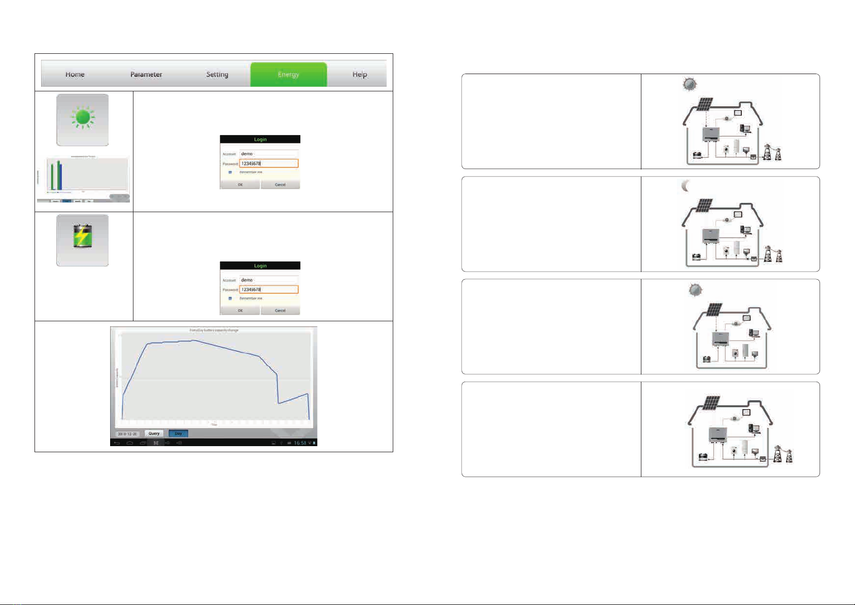
The hybird series inverters (hybrid) of ReneSola are bidirectional which apply to PV system with battery to store energy.
Energy produced by the PV system is used to optimize self-consumption; excess energy is used to charge the batteries, and then fed
into the public grid when the PV energy is adequate,
When PV energy output is insufficient to support connected loads, the system automatically get energy from the batteries if battery
capacity is abundant. If the battery capacity is insufficient to meet own consumption requirements, electricity will be drawn from the
public grid.
The series inverter of ReneSola is design for both indoor and outdoor use.
Figure 1-1 Basic hybrid PV system overview
2.1 Symbols
Product should not be disposed as
household waste.
CE Mark
Keep dry; the package/product must be
protected from excessive humidity and must be
stored under cover.
Signals danger due to electrical shock and indicates the time (5 minutes) to allow after the
inverter has been turned off and disconnected to ensure safety in any installation operation.
The package/product should be handled
carefully and never be tipped over or slung.
2.2 Safety
● Installation, maintenance and connection of inverters must be performed by qualified personnel, in compliance with local electrical
standards, wiring rules and the requirements of local power authorities and/or companies.
● To avoid electric shock, DC input and AC output of the inverter must be terminated at least 5 minutes before performing any
installation or maintenance.
● The temperature of some parts of the inverter may exceed 60℃ during operation. To avoid being burnt, do not touch the inverter
during operation. Let it cool before touching it.
● Ensure children are kept away from inverters.
● Do not open the front cover of the inverter. Apart from performing work at the wiring terminal (as instructed in this manual),
touching or changing components without authorization may cause injury to people, damage to inverters and annulment of the
warranty.
● Static electricity may damage electronic components. Appropriate method must be adopted to prevent such damage to the
inverter; otherwise the inverter may be damaged and the warranty annulled.
● Ensure the output voltage of the proposed PV array is lower than the maximum rated input voltage of the inverter; otherwise the
inverter may be damaged and the warranty annulled.
● When exposed to sunlight, the PV array generates dangerous high DC voltage. Please operate according to our instructions, or it
will result in danger to life.
● PV modules should have an IEC61730 class A rating.
● If the equipment is used in a manner not specified by the manufacturer, the protection provided by the equipment may be
impaired.
● Completely isolate the inverter should :Switch off the DC switch, disconnect the PV terminal, disconnect the battery terminal,
and disconnect the AC terminal.
● Completely isolate the inverter before maintaining. Not to enter other areas of the inverter when maintaining!
● Prohibit to insert or pull the AC and DC terminals when the inverter is running.

03 04
Wall-mounted
Bracket×1
Inverter×1Positive DC Plug×2
or
Negative DC
Plug×2
or
Figure 3.3-1
Expansion Bolts×6
User Manual×1
User
manual
Quick Installation
Guide×1
Warranty
Card
Wi-Fi Connection
Guide×1
Wi-Fi Connection
Configuration
1. Battery input
2. PV input terminals
3. DC Switch (Optional)
4. Wi-Fi antenna port
5. USB port
6. RS-485 port
7. AC output terminals
8. LED lights
terminals
3.2 Product Overview
1 2 3 4
5
8
6 7
Mounting location should be selected based on the following aspects:
● The installation method and mounting location must be suitable for the inverter's weight and dimensions.
● Mount on a solid surface.
● Select a well ventilated place sheltered from direct sun radiation.
● Install vertically or tilted backward by max 15°. The device cannot be installed with a sideways tilt. The connection area must point
downwards. Refer to Figure 3.3-1.
USB Data Cable×1
Battery cover × 1
EzMeter × 1
EzConverter
(optional) × 1
AC cover × 1 AC terminal × 6 Battery terminal × 2
Hexagon head
screw × 2 Pan head screw × 8
Flat head screw × 5
Max
15°
●
than the following value:
In consideration of heat dissipation and convenient dismantlement, the minimum clearances around the inverter should be no less
Upward ----------300mm
Downward--------500mm
Front-------------300mm
Both sides---------500mm
Figure 3.3-2
300mm
500mm
500mm 500mm 300mm
Antenna×1
Warranty card×1
Instruction
of
Fast
Installation
3.3 Selecting The Mounting Location
●
● For the convenience of checking the LED lights and possible maintenance activities, please install the inverter at eye level.
● Inverters should NOT be installed near inflammable and explosive items. Any strong electro-magnetic equipment should be kept
away from installation site.
● Product label and warning symbol shall be clear to read after installation.
● Please avoiding direct sunlight, rain exposure, snow lay up when installing.
In order to achieve optimal performance, the ambient temperature should be lower than 45 °C.
Direct Sunlight Rain Exposure Snow Lay up
No direct sunlight No Rain Exposure No Snow Lay up
3.1 Packing List
3 Installation
Before installation, please inspect the unit. Be sure that nothing inside the package is damaged. You should have received the
following items inside of package:

05 06
Grade Description
A O.D.
B
C Bare Wire Length
Figure 4.1-1
AB
C
AB
C
4 Electrical Connection
4.1 AC Output Connection
Conductor Material
Sectional Area
Value
10~12mm
2
3~4mm
10mm around
Before connecting to Grid and Load, please install a separate AC breaker (250VAC/30A)between inverter and Grid. This will
ensure the inverter can be securely disconnected during maintenance.
It's very important for system safety and efficient operation to use appropriate cable for AC connection. To reduce risk of
injury, please use the proper recommended cable size. Refer to Figure 4.1-1.
Please follow below steps to implement AC connection:
(1) Check the grid voltage and frequency at the connection point of the inverter. It should meet ReneSola product Spec.
(2) Measure the impedance between neutral cable and earth cable, make sure it is not excess than 10 ohm.
(3) Disconnect AC breaker between inverter and Grid.
(4) Disconnect screw cap from insulator.
(5) Disconnect waterproof ring from insulator.
(6) Put the cable through the components in this order: screw cap, waterproof ring, insulator, AC cover and AC terminal. Refer to Figure
4.1-2.
(7) Compress the terminal head by professional tool and screw down screw cap slight. Refer to Figure 4.1-3, Figure 4.1-4.
(8) Insert AC terminals into the corresponding holes and fasten them by screwdriver (Suggest: diameter of the cutter bar is 4mm,
torsion:8~12Kg-f.cm), then fasten AC cover with pan head screws in accessory bag. Refer to Figure 4.1-5, Figure 4.1-6, Figure 4.1-7.
(9) Screw down screw cap again.
Figure 4.1-2 Figure 4.1-3
Cable Waterproof ring AC cover AC terminal
Screw cap Insulator Crimp
Figure 4.1-4
Cable core section after crimp
Figure 4.1-7
Pan head screw
Figure 4.1-5
L----line N----neutral PE----earth
back-up terminal grid terminal
Figure 4.1-6
Figure 3.4-3 Figure 3.4-4
a
b
detail a
detail b
Figure 3.4-1 Figure 3.4-2
457mm
229mm
117mm
105mm
400mm
Remember that this inverter is heavy! Please be carefully when lifting out from the package.
1. Use the wall-mounted bracket as a template and drill 6 holes on the wall, 10 mm in diameter and 80 mm deep. Refer to Figure
3.4-1.
2. Fix the wall-mounted bracket on the wall with six expansion bolts in accessory bag.
3. Carry the inverter by holding the heat-sink two sides. Refer to Figure 3.4-2.
4. Place the inverter on the wall-mounted bracket. Refer to Figure 3.4-3、 Figure 3.4-4.
3.4 Mounting

Grade Description
A O.D.
B
C Bare Wire Length
Conductor Material
Sectional Area
Value
10~12mm
2
20~25mm
10mm around
0807
Figure 4.2-3
Installation instruction of SUNCLIX please refer to Figure 4.2-2.
Installation instruction of MC4 please refer to Figure 4.2-3.
Negative plug
Positive plug
Figure 4.2-2
Figure 4.3-1
AB
C
Special tools are used to stitching
Inverter side
4.3 Battery Connection
Before connecting to battery, please install a separate DC breaker (60A for Replus 3648ME and 120A for ) between
inverter and battery. This will ensure the inverter can be securely disconnected during maintenance.
● Be aware of electric shock and chemical hazards!
● It is a normal phenomenon that electric arc occurs when connecting battery to the inverter without use a DC breaker.
● It's very important for system safety and efficient operation to use appropriate cable for battery connection. To reduce risk of
injury, please use the proper recommended cable size. Refer to Figure 4.3-1.
Replus 5048ME
● if t to be for
● Suggestion: Batteries must be installed with a distance to each other, details please refer to battery manufacture's user manual.
● As for the number of cells used, it will be decided by customer's choice, the choice must comply with the followed requirement:
the rated voltage is 48V.
Please follow below steps to implement battery connection:
(1) Check the nominal voltage of batteries. The nominal output voltage should meet ReneSola product Spec.
(2) Disconnect DC breaker between inverter and battery.
(3) Disconnect screw cap from insulator.
(4) Disconnect waterproof ring from insulator.
(5) Put the cable through the components in this order: screw cap, waterproof ring, insulator, battery cover and battery terminal.
Refer to Figure 4.3-2.
(6) Compress the terminal head by professional tool and screw down screw cap slight. Refer to Figure 4.3-3, Figure 4.3-4.
(7) Put battery terminals into the corresponding holes and fasten them by screwdriver and spanner (recommended torsion:50~70Kg-
f.cm), then fasten battery cover with pan head screws in accessory bag. Refer to Figure 4.3-5, Figure 4.3-6, Figure 4.3-7.
(8) Screw down screw cap again.
Suggestion: he battery is installed indoor, details please refer to battery manufacture's user manual.
Positive plug
Negative plug
Inverter side
7mm
7mm
2
2.5~4mm
2
2.5~4mm
Figure 4.3-3
Crimp
Cable
Figure 4.3-2
Waterproof ring
Battery cover
Battery terminal
Screw cap
Insulator
SUNCLIX Series MC4 Series
Figure 4.2-1
There are two types of DC plugs, SUNCLIX and MC4 series. Please refer to Figure 4.2-1.
●
permanently damage the inverter.
·● Check the short-circuit current of the PV string. The total short-circuit current must not exceed the inverter’s maximum PV current.
·● PV array should not be connected to the grounding conductor.
·● Must be use DC plugs in accessory bag.
·● The minimum insulation resistance to ground of the PV pannels must exceed 19.33kΩ, there is a risk of shock hazard if the
requirement of minimum resistance is not met.
Before connecting the PV panels, ensure the plug connectors have the correct polarity. Incorrect polarity could
4.2 PV Connection
● Reversed polarity will damage the inverter!

09 10
RS-485 interfaces are used for EzConverter and EzMeter communication. The cable length should not exceed 800m. For the
connection methods of RS-485 please refer to chapter 4.5, chapter 4.6.
Please follow below steps to implement RS-485 connection of inverter side:
● Remove RS-485 waterproof assembly from inverter.
● Disconnect screw cap from insulator.
● Disconnect waterproof ring from insulator.
● Put the cable through the components in this order: screw cap, waterproof ring, insulator, RS-485 cover. Refer to Figure 4.4-1.
● Put cable cores insert into the corresponding slots and compress the crystal head by professional tool, then screw down screw cap
slight. Refer to Figure 4.4-1.
● Put crystal head insert into the corresponding inner slots of inverter.
● Fasten RS-485 waterproof assembly to inverter.
● Screw down screw cap again.
4.4 RS-485 Connection
Figure 4.3-4 Figure 4.3-5
Cable core section after crimp
+ ----red cable - ----black cable
Positive
terminal
Negative
terminal
Figure 4.3-6 Figure 4.3-7
Hexagon head screw Pan head screw
4.5 EzMeter Connection
EzMeter can detect the current magnitude and direction, to control the working condition of inverter. Inverter and EzMeter
communication via RS-485, The cable length should not exceed 800m.
For the connection method of single phase EzMeter refer to Figure 4.5-1.
Cable Waterproof ring RS-485 cover Crystal head
Screw cap Insulator
Figure 4.4-1
PIN
1
2
3
4
5
6
7
8
Color
Orange/white
Orange
Green white/
Blue
Blue white/
Green
Brown white/
Brown
RS-485 waterproof assembly
RESERVED
RX RS485B_
RX_RS485A
TX RS485B_
TX RS485A_
Function
RESERVED
RESERVED
RESERVED
Load
PIN
1
2
3
4
5
6
7
8
RESERVED
RX RS485B_
RX_RS485A
TX RS485B_
TX RS485A_
Function
Color
Orange white/
Orange
Green white/
Blue
Blue white/
Green
Brown white/
Brown
RESERVED
RESERVED
RESERVED
Breaker
Connection Illustration of Single Phase System
T568B
Grid
Figure 4.5-1
EzMeter
If the light is flashing, the connection is ok.
Breaker
RESERVED
Function
Color
Orange/white
Orange
Green white/
Blue
Blue white/
Green
Brown white/
Brown
RESERVED
RESERVED
RESERVED

11 12
For the connection method of three phases EzMeter refer to Figure 4.5-2.
Load
Connection Illustration of Three Phase System(optional)
Figure 4 5-2.
EzMeter
Breaker
Grid
Breaker
RESERVED
Function
Color
Orange/white
Orange
Green white/
Blue
Blue white/
Green
Brown white/
Brown
RESERVED
RESERVED
RESERVED
PIN
1
2
3
4
5
6
7
8
RESERVED
RX RS485B_
RX_RS485A
TX RS485B_
TX RS485A_
Function
Color
Orange white/
Orange
Green white/
Blue
Blue white/
Green
Brown white/
Brown
RESERVED
RESERVED
RESERVED
T568B
4.6 EzConverter Connection (optional)
It is needed to configure EzConverter if lithium battery is used in the system, to communicate with battery BMS.
Inverter and EzConverter communication via RS-485, lithium battery and EzConverter communication via RS-485 or CAN or RS-232
(depend on Li-Ion battery communication type).The cable length should not exceed 2m.
Choose corresponding dial-up circuit of lithium battery, according to dial-up protocol comparison table of lithium battery from user
manual.
● Lithium battery communication connects to EzConverter via RS-485 interface if lithium battery communication protocol is RS-485.
Refer to Figure 4.6-1.
● Lithium battery communication connects to EzConverter via CAN interface if lithium battery communication protocol is CAN. Refer
to Figure 4.6-2.
● Lithium battery communication connects to EzConverter via RS-232 interface if lithium battery communication protocol is RS-232.
Refer to Figure 4.6-3.
RS-485
Figure 4.6-1
Battery
Li-Ion
T568B
PIN
1
2
3
4
5
6
7
8
RESERVED
RX RS485B_
RX_RS485A
TX RS485B_
TX RS485A_
Function
Color
Orange white/
Orange
Green white/
Blue
Blue white/
Green
Brown white/
Brown
RESERVED
RESERVED
RESERVED
CAN
Figure 4.6-2
Battery
Li-Ion
T568B
PIN
1
2
3
4
5
6
7
8
RESERVED
RX RS485B_
RX_RS485A
TX RS485B_
TX RS485A_
Function
Color
Orange white/
Orange
Green white/
Blue
Blue white/
Green
Brown white/
Brown
RESERVED
RESERVED
RESERVED
RS-232
Figure 4.6-3
Battery
Li-Ion
T568B
PIN
1
2
3
4
5
6
7
8
RESERVED
RX RS485B_
RX_RS485A
TX RS485B_
TX RS485A_
Function
Color
Orange white/
Orange
Green white/
Blue
Blue white/
Green
Brown white/
Brown
RESERVED
RESERVED
RESERVED
EzConverter work status as below table4.6-1.
TABLE4.6-1
Silk-Screen
Power
Inverter
RS-485
CAN
RCR
RS-232
LED Color
Green
Yellow
Yellow
Yellow
Yellow
Yellow
EzCoverter Status Note
Powered on
Communicate with Inverter
Communication OK
Communication OK
Received command from RCR
Communication OK
LED Display Status
Constant on
Blink
Blink
Blink
Blink
Blink
If the light is flashing,
the connection is ok.

Inverter Status
Wi-Fi
Normal
Fault
Sale
Buy
Charge
Discharge
Bat Low
Inverter Status Note
Wi-Fi Reset or Reload OK
Wi-Fi Router NG
Wi-Fi Server NG
Wi-Fi Server OK
Normal
Checking
Fault
Grid Fault
Generate to grid
Feeding to Grid is Off
Consumption from grid
Battery Charging
Battery Discharging
Battery Low / Bad / Disconnect
LED Color
Yellow
Green
Red
Blue
Blue
Blue
Blue
Red
LED Display Status
Blink 0.2s on 0.2s off
Blink 0.5s on 0.5s off
Blink 2.5s on 2.5s off
Constant on
Constant on
Blink 0.5s on 0.5s off
Constant on
Blink 2s on 2s off
Constant on
Blink 2s on 2s off
Constant on
Constant on
Constant on
Blink 1s on 1soff
13 14
Figure 4.7-1
4.7 Wi-Fi Connection
Install the antenna to inverter. Refer to Figure 4.7-1.
4.8 Wi-Fi Reset & Reload
Wi-Fi reload function is used to change the Wi-Fi configuration to default value. Please reconfigure the Wi-Fi as per Wi-Fi configure
illustration after using the function.
● Long press(more than 5s, less than 8s) the touch switch until the LED Wi-Fi displays“Blink 0.5s on 0.5s off”, stop pressing and Wi-
Fi reset is successful. Refer to Figure 4.8-1
● Long press(more than 20s, less than 30s) the touch switch until the LED Wi-Fi displays“Blink 0.5s on 0.5s off” twice, stop pressing
and Wi-Fi reload is successful. Refer to Figure 4.8-1.
Figure 4.8-1
Open USB cover
Touch switch
5 LED Lights Illustration
6 EzManage Operation Illustration
Hybrid Series inverter has no LCD screen, it can be controlled via mobile device with the APP software (EzManage).
6.1 Download and Install
●
Besides, through scan the QR code to be installed on the back cover too.
Google play: http://play.google.com/store/apps/details?id=com.renesola.EzManage.
6.2 Setting
If this is your first time to install ReneSola Hybrid Inverter, please first connect the battery and solar panels to the inverter and keep
the inverter off-grid, then you can set the inverter in “Setting” menu through Ezmanage with the following steps. After finishing the
setting, connect to grid, Then the inverter starts to work.
(1) Wi-Fi communication
Communication
Plan 2.Connect through wireless router!
If inverter has joined local Wi-Fi network, you can choose the SSID of Wi-Fi router and join it.
Plan 1.Connect the inverter directly!
Please choose the SSID of inverter (Solar-Wi-Fi as default, initial password:12345678) and join it.
Country for Safety Setting
Attention :
After setting successfully ,please disconnect the power of PV, battery, grid, and then connect
the power again!
If you have any questions, please refer to .
(2) Select “Safety Country ”
Wi-Fi Connection Guide
Safety Country
4.9 USB Connection
The USB communication is used for firmware update only!
Please follow below Figure 4.9-1 to implement USB connection:
Figure 4.9-1
Open USB cover
Insert USB data cable

15 16
Click to synchronize time setting with your monitoring device
(3) Set “Synchronize Time”
Battery Setting
(4) "Battery Selection"
1.Please choose the right battery information according to your actual situation, and choose
the "Default"if there is no option for Manufacturer and Model!
2.Please choose the correct capacity of battery, and if there is no corresponding capacity,
then choose the closest value!
Battery Setting
Grid Charge Time: During this time period, gird will charge battery automatically.
Grid Charge Power: Set grid charge power limits(0-50%).
Battery Discharge Time: During this time period, the battery will discharge.
Battery Discharge Power: Set battery discharge power limits(0-100%).
Attention:
If there is overlap between charge time and discharge time,charge is preferred.
Battery Selection
Advanced Settings
Feeding To Grid: When the switch is "yes", excess energy of PV can feed to grid.
Shadow Scan: When switch is "on", it can resolve the multiple wave problems of PV pannels.
PV Charge Without Grid: When switch is "on", PV can charge battery without grid. This
Function can be set in off-grid and must have PV.
Back-up Function: When switch is "on", it allows the Back-up port to output.
Start Back-up Output: When grid is unreachable, we can start Back-up manually.
(5)
(If you have already install a ReneSola EzMeter, you can skip to next step, because ReneSola Hybrid Inverter will automatically
control the Battery charging and discharging based on your demand.)
Battery Management
(6) "Function Setting"
6.3 Current Data Display
Check PV parameters
Check battery parameters
PV
Check grid parameters
Battery
Check load parameters
Grid
Check inverter parameters
Load
Inverter
Synchronize Time
Battery Management
Advanced Setting

Solar Yield
6.4 Historical Data Display
Battery Capacity
Solar Yield
Please ensure that the monitoring device has been connected with the Internet and solar
station has been successfully created.
Please enter the registered user name and password when you created the solar station.
Three historical data display formats, “Year” ”Month” and “Day”. Defaulted as “Year”. Click
“Query” for selection.
Check the battery level
Please ensure that the monitoring device has been connected with the Internet and solar
station has been successfully created.
Please enter the registered user name and password when you created the solar station.
7. Work Modes
Hybrid series inverters have the following main work modes based on different conditions:
Mode1:
Energy produced by the PV system is preferred for local
load. And the excess energy is first used for charging
batteries, then feeding to the grid.
Mode2:
If there is no PV, battery energy is used for local load
first, the grid also can supply when the battery capacity
is not enough.
Mode3:
If the grid is fault or there is no grid, the system can still
work, PV and batteries supply energy for local load.
Mode4:
The battery can be charged by the grid, time and power
of battery charging can be set up flexibly.
17 18

An error message will be displayed on the APP if a fault occurs.
Table 8-1 is the Description of Error Message
Error message
Utility Loss
Fac Failure
PV Over Voltage
Over Temperature
Isolation Failure
Ground I Failure
Relay-Check Failure
DC Injection High
EEPROM R/W Failure
SPI Failure
DC Bus High
AC HCT Failure
GFCI Failure
Vac Failure
Battery Over Temperature
Battery Under Temperature
Battery Cell Voltage Differences
Battery Over Total Voltage
Battery Discharge Over Current
Battery Charge Over Current
Battery Under SOC
Battery Under Total Voltage
Battery Communication Fail
Battery Output Short
Description
Grid disconnected
Grid frequency no longer within permissible range
Overvoltage at DC input
Overtemperature on the case
Ground insulation impedance is too low
Overhigh ground leakage current
Relay self-checking failure
Overhigh DC injection
Memory chip failure
Internal communication failure
Overhigh BUS voltage
Output current sensor failure
Detection circuit of ground leakage current failure
Grid voltage no longer within permissible range
Battery Over Temperature
Battery Under Temperature
Li-Ion Battery Cell Voltage Differences
Li-Ion Battery Over Total Voltage
Battery Discharge Over Current
Battery Charge Over Current
Battery Capacity Low
Battery Under Total Voltage
Battery Communication Fail
Battery Output Short
8 Error Messages 9 Technical Parameters
Model
Category Ⅱ
SUNCLIX / MC4 (Optional)
Replus 5048ME
5400
580
125~550
125
15/15
20
2
2(can parallel)
Lead-acid or Li-Ion
48
4600
5-50 A continuous, programmable
>100AH(depending requirement)
3-stage adaptive with maintenance
57V
included(Li-Ion)
integrated
integrated
4600
4600
1.5x Pnom, 10sec
20
30
Replus 3648ME
4200
580
125~550
125
15/15
20
2
2(can parallel)
Lead-acid or Li-Ion
48
4600
5-50 A continuous, programmable
>100AH(depending requirement)
3-stage adaptive with maintenance
57V
included(Li-Ion)
integrated
integrated
3600
3600
1.5x Pnom, 10sec
16
24
99.9%
50/60Hz; 230Vac
45~55Hz/55~65Hz; 180~270Vac
230Vac ±2%, 50Hz ±0.2%, THDv<3%(linear load)
<1.5%
0.9 leading~0.9 lagging
Single phase
Category Ⅲ
97.6%
97.0%
97.6%
97.0%
*
Solar
Max. DC power(W)
Max. DC voltage (V)
MPPT voltage range (V)
Starting voltage (V)
Max. DC current (A)
DC overcurrent protection(A)
No. of DC connectors(Pr)
No. of MPPTs
DC overvoltage category
DC connector
Battery
Battery Type
Battery Rated voltage (V)
MAX Discharge power (W)
Charge current (A)
Battery capacity (Ah)
Charging curve
Charging voltage
Battery temperature compensation
Battery voltage sense
Current shunt
AC Output Data
Norminal AC power(W)
Max. AC power(W)
Peak power (Back-up)(W)
Max. AC current(A)
AC overcurrent protection(A)
Norminal AC output
AC output range
AC output (Back-up)
THDi
Power factor
Grid connection
AC overvoltage category
Efficiency
Max. efficiency
Euro efficiency
MPPT adaptation efficiency
19 20
Table 8-1

21 22
VDE4105, VDE 0126-1-1+A1, G83/2, G59/3, AS4777.2/.3
IEC62109-1&-2, AS3100, IEC62040-1
EN61000-6-1, EN61000-6-2, EN61000-6-3, EN61000-6-4, EN61000-3-11, EN61000-3-12
30 28
516*440*184mm 516*440*184mm
Protection
Residual current monitoring unit
Anti-islanding protection
DC switch(PV)
AC over current protection
Insulation monitoring
Certifications&Standards
Grid regulation
Safety
EMC
General Data
Dimensions (WxHxD)
Weight (kg)
Mounting
Ambient temperature range
Relative humidity
Moisture location category
Max. operating altitude
Protection degree
Environment category
External environment pollution degree
Topology
Standby losses(W)
Cooling
Noise emision(dB)
Display
Communication
Standard warranty(years)
Integrated
Integrated
Integrated (optional)
Integrated
Integrated
Wall-mounted
-25~60°C (>45°C derating)
0~95%
4K4H
2000m
IP65
Outdoor & indoor
Grade1、2、3
Transformerless
<8
Nature convection
<25
LED light & APP
USB2.0 or Wi-Fi
5/10/15/20/25 (optional)
Bracket
Model Replus 5048ME Replus 3648ME
*
listed in the table.
It is recommended that the total peak power of PV strings should not exceed 130% of maximum DC power of inverter 10 Certificates
59 VDE0126-1-1
Note
Overvoltage category definition
Category I : applies to equipment connected to a circuit where measures have been taken to reduce transient overvoltage to a
low level.
Category II : applies to equipment not permanently connected to the installation. Examples are appliances, portable tools and
other plug-connected equipment;
Category III: applies to fixed equipment downstream of and including, the main distribution board. Examples are switchgear
and other equipment in an industrial installation;
Category IV: applies to equipment permanently connected at the origin of an installation (upstream of the main distribution
board). Example are electricity meters, primary overcurrent protection equipment and other equipment connected
directly to outdoor open lines.
Environment category definition
Outdoor : the ambient air temperature is -20~50°C, Relative humidity range is 4 % to 100 %, applied to PD3
Indoor unconditioned: the ambient air temperature is -20~50°C, Relative humidity range is 5 % to 95%,applied to PD3
Indoor conditioned: the ambient air temperature is 0~40°C, Relative humidity range is 5 % to 85%,applied to PD2
Pollution degree definition
Pollution degree 1: No pollution or only dry, non-conductive pollution occurs. The pollution has no influence.
Pollution degree 2: Normally only non-conductive pollution occurs. Occasionally, however, a temporary conductivity caused by
condensation must be expected.
Pollution degree 3: Conductive pollution occurs, or, dry, non-conductive pollution occurs which becomes conductive due to
condensation which is expected.
Pollution degree 4: Persistent conductive pollution occurs, for example, the pollution cause by conductive dust, rain and snow.
Moisture
parameters
Level
Temperature Range
Humidity Range
3K3
0~+40℃
5%~85%
4K2
-33~+40℃
15%~100%
4K4H
-20~ +55°C
4%~100%
Moisture location category definition
This manual suits for next models
1
Table of contents