Setec Power SET-IVS9000 Series User guide

1
SET-IVS9000 Series Sine-Wave Inverter
SET12/220-XXXX KLC
SET24/220-XXXX KLC
SET48/220-XXXX KLC
SET110/220-XXXX KLC
SET220/220-XXXX KLC
System Manual
Shenzhen SETEC Power Co., Ltd
Address: #199, Setec Industrial Park, Dakan, Xili Town, Nanshan District,
Shenzhen ,China
Tel: 0755-26527891, 26527426, 26527137
Fax: 0755-26527104
Web: http://www.setec.com.cn
http://www.setec-power.com

2
【Precautions】
Before operating, please read the users manual to learn the proper use of
equipment. Please keep this manual for future use.
Warning: The machine should be installed by trained engineers, please make
sure to clarify the following issues before installation:
Voltage provided by the dc bus, whether it is rated dc input voltage of the
inverter. Red line connect positive of battery, black connect negative of
battery. Please pay attention to the negative and positive connection.
◆When install the battery pack, it should follow connection instructions of
battery. Wires must be wrapped tightly. Pls don’t make the positive and
negative short circuit, while prohibit to touch any battery terminals and
naked wires, otherwise the battery will be damaged or cause personal injury.
◆Even if AC power is disconnected, there will be some high voltage inside
which will threaten personal safety.
◆There should add the MCB in front of DC input and AC input,in order to
disconnect the power easily when maintain and inverter failures.
◆Pls do not remove cover or any parts inside. There is fatal voltage or
dangerous high energy in the parts inside the device!

3
Table of Contents
1. SET-IVS9000 SERIES SUMMARIZE...................................................1
2. SET-IVS9000 SERIES FEATURES .....................................................1
3. SET-IVS9000 SERIES MODEL NOTES:.............................................2
4. SET-IVS9000 SERIES MODEL TABLE...............................................2
5. SET-IVS9000 SERIES INTERNAL BLOCK DIAGRAM ......................3
6. SET-IVS9000 SERIES MODEL USE METHOD...................................3
7. SET-IVS9000 SERIES MAINTENANCE INFORMATION....................4
8. SET-IVS9000 SERIES LCD MENU CONTENT...................................9
9. SET-IVS9000 SERIES MODEL TECHNICAL
SPECIFICATIONS.....................................................................................7
10. SET-IVS9000 SERIES MECHANICAL PROPERTIES ......................9
11. ACCESSORY...................................................................................13
12. NOTE................................................................................................14
QUALITY ASSURANCE CARD..............................................................15

4
1. SET-IVS9000 Series Summarize
SET series of pure sine-wave inverter is special designed and produced for the actual needs of
electric power system and the telecommunications, considering the space installation size, the
demand for IT era inverter management automation and networking and the influence of noise on
office or room staff.
This series inverter adopts advanced SPWM and CPU control technology, control precision,
input and output isolation, safely and high efficiency, good reliability, especially the strong ability to
withstand the impact of inductive loads. This series of products are not only small volume, light weight,
beautiful appearance, convenient installation and maintenance, easy operation, low noise, low
reflected noise, no pollution, but also have real time data acquisition and remote communication
function. It is a convenient system for the majority of users with implementation of network
management and remote monitoring.
It is not only applicable to the communications industry, but also for the other to supply high
quality power requirements occasion, an ideal power choice for the office automation.
2. SET-IVS9000 Series Features
1) SET-IVS9000 series inverter is the intelligent power inverter, using intelligent
microcomputer CPU control technology, the control circuit is simple, reliable, and fast
response to changes in the external environment;
2) SET-IVS9000 series inverter adopting SPWM technology, the output is pure sine-wave with
stabilized voltage and frequency, filtering noise and low distortion;
3) The SET –IVS9000 series inverter has strong load capacity, good load compatibility, built-in
bypass switch, which improve the continuity and reliability of the inverter power supply;
4) SET-IVS9000 series inverter DC input adopts advanced reflected noise suppression
technology, without interfering with other communication devices which shared DC power,
and AC input use multiple filtering technology to eliminate mains interference, which meet
the application needs of using main AC power;
5) SET-IVS9000 series inverter has 2 working types: AC power type and DC power type (It
can be modified via LCD panel or communication background software);
(1) AC power type means the city power supply is main when the city power is normal, when
city power off, inverter comes into work state;
(2) DC power type means the inverter power supply is main when the city power is normal,
when inverter power is off, city power comes into work state automatically;
6) With the excellent design, SET-IVS9000 series inverter can be automatically switched to
bypass on the running state. It’s easy to maintain and replace the battery without effecting
load power supply;
7) In case battery voltage is high/low or overload, the inverter will shut off. When battery
voltage returns to normal, the inverter will automatically switch on; when overload was
eliminated, the inverter will also automatically switch on. This feature is especially suitable
for unattended communication base stations;
8) SET-IVS9000 series inverter with LCD display, users can see the data anytime. LCD
screen uses 1602B, 122 * 32 dot matrix, blue background, silver-white subtitles;
9) SET-IVS9000 Series Inverter support AC power on, in case of DC power fault conditions;
10) SET-IVS9000 series inverter can support network communication system, power working

5
state can be monitored by the supervision software (optional);
11) SET-IVS9000 series inverter supports TCP / IP protocol functions. It uses monitoring software
to remote control single / multiple inverters via Ethernet(optional);
12) SET-IVS9000 series inverter provides three sets of passive dry contacts (with separate dry
contact interface), respectively for the DC input failure (1,2 pin), AC input failure (5,6 pin) and AC
output failure (3,4 pin) alarms.
3. SET-IVS9000 Series Model Notes:
SET 48 / 220- 2k LC
LC----19 Inch Rack Type (LCD panel)
2K—Power (VA)
220---AC Output Voltage (V)
48---DC Input Voltage (V)
SET--- SETEC Company Code
4. SET-IVS9000 Series Model Table
SET 12 Series
SET 24 Series
SET 48 Series
SET 110 Series
SET 220 Series
500VA
SET12/220-500LC
SET24/220-500LC
SET48/220-500LC
SET110/220-500LC
SET220/220-500LC
1KVA
SET12/220-1KLC
SET24/220-1KLC
SET48/220-1KLC
SET110/220-1KLC
SET220/220-1KLC
2KVA
-
SET24/220-2KLC
SET48/220-2KLC
SET110/220-2KLC
SET220/220-2KLC
3KVA
-
SET24/220-2.5KLC
SET48/220-3KLC
SET110/220-3KLC
SET220/220-3KLC
4KVA
-
-
SET48/220-4KLC
SET110/220-4KLC
SET220/220-4KLC
5KVA
-
-
SET48/220-5KLC
SET110/220-5KLC
SET220/220-5KLC
6KVA
-
-
SET48/220-6KLC
SET110/220-6KLC
SET220/220-6KLC
7KVA
-
-
SET48/220-7KLC
SET110/220-7KLC
SET220/220-7KLC
8KVA
-
-
SET48/220-8KLC
-
SET220/220-8KLC
9KVA
-
-
SET48/220-9KLC
-
SET220/220-9KLC
10KVA
-
-
SET48/220-10KLC
-
SET220/220-10KLC
6
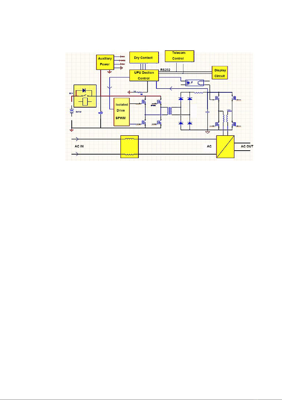
5. SET-IVS9000 Series Internal block diagram
6. SET-IVS9000 Series Model Use Method
6.1 Preparation (To install the inverter, it requires technical staff who has some
knowledge of electrical theory and practical experience)
a) Open the package and check accessories
b) Choose a clean and ventilation area.
c) Make sure DC voltage and battery voltage match with what inverter requires.
d) Check the power Positive and Negative line, high potential is positive, the low potential is
negative (for example:-48VDC power supply, 0V terminal is positive,-48V side is negative, +24 V
power supply, +24 V terminal is positive, 0V side is negative)
6.2 wiring
A) To ensure reliable connection, connecting Positive Cable with the terminal“+”,negative
Cable with the “-”;
B) You can test machine only when DC input is available to confirm whether the machine and
power is normal;
C) Connecting AC input wire with ―AC IN‖ terminal on the inverter. Pls note ―L N‖ phase. At the
same time, AC Ground wire must be connected into ground well.
D) Connecting load cables with AC output terminals ―AC OUT‖ on the inverter.
6.3 Start
Switches : Left-Right reciprocating type
a) Make sure that DC input, AC input and AC output cables are right connected.
b) Switch mode: switch to "○" for the shutdown, switch to "-" for the boot.
c) Press the switch to the "-" terminal,after hear a "beep" sound, inverter comes into the state
of self-inspection, which means inverter is on.
Notes: Self-inspection------Before the output is stable delivered, check the external environment

7
and whether inverter is normal. When all parameters of inverter is normal, the inverter will be in
working status of AC power main or DC power main. It takes about 10 seconds. LED indicators
lights from left to right two times during this period.
Shutdown mode: Switch to "○" direction, the machine will be shut down.
6.4 Mute switch
If the inverter failed during operation, the system will sound an alarm, audible alarm can be
turned off via , the button is touch type.
Press the twice ,you can control sound alarm: Press the again,alarm will be closed;
press the twice, the alarm sounds again be opened. If there is same problem, the inverter
will not be alarmed again in mute state. When the new problem occurs, the inverter will also
alarm.
6.5 Communication parameters
The are 3 kinds of communication interface: RS232, RS485 ,TCP / IP, but only choose on from
them .Baud rate is up to 9600.
7. SET-IVS9000 Series Maintenance information
Button and the Definition of LED light
On / off button—SWITCH
"Power output" green light: Return button
"Inverter output" blue light: Menu button: up
"Battery Fault" red light: Menu button: down
"Load Fault" red light: OK button:
8
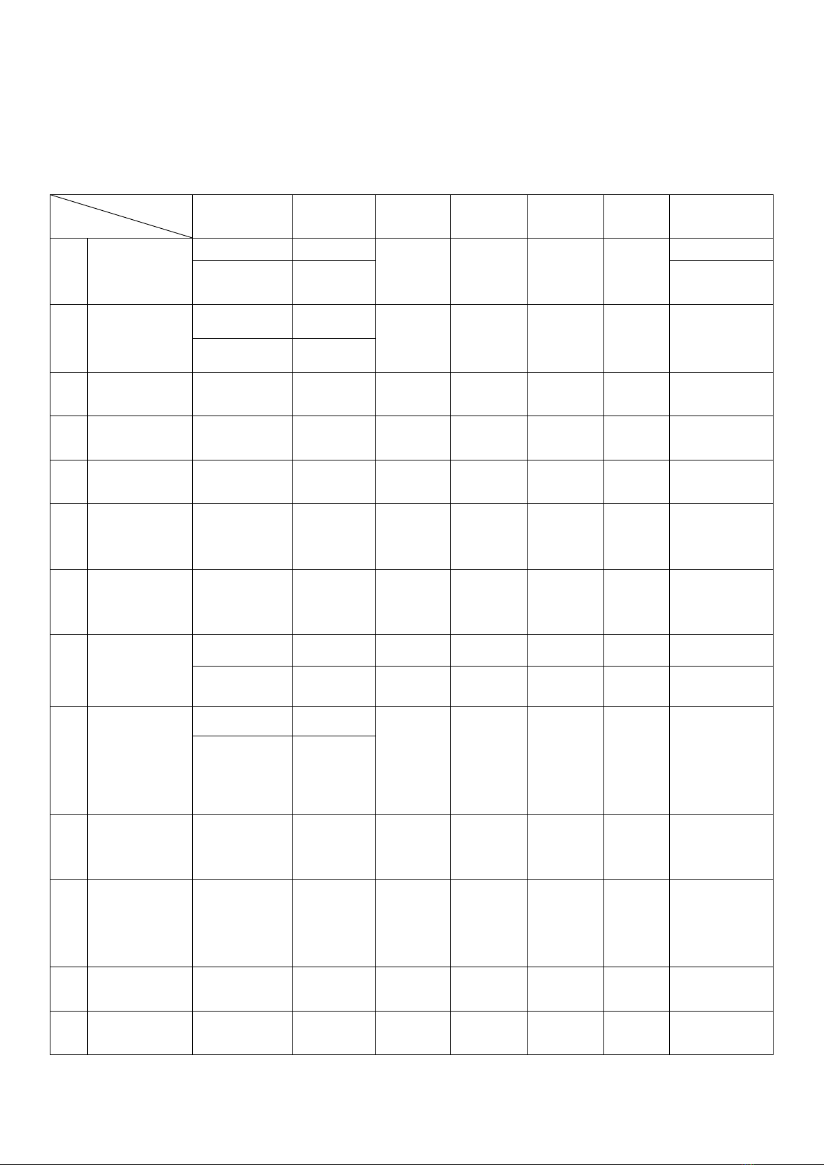
Chart 1: Indicator and Combination ((F)BAC12A (F)BDC12A (F)BAC35A
(F)BDC35A )
Status
Item
Output
Output
Type
Power
Green
Inverter
Blue
Battery
Red
Load
Red
Buzzer
1
Self Test
Yes
Power
→On→
→On→
→On→
→On→
A sound/1s
No
Inverter
3sound/
muted
2
Self Test
Battery
Failure
Yes
Power
Dark
Light
Blink
Dark
Blew
No
No
3
Power
Normal
Yes
Power
Light
Dark
Dark
Dark
No
4
Power
Abnormal
Yes
Inverter
Dark
Light
Dark
Blink
A Sound/3s
5
Inverter
Normal
Yes
Inverter
Dark
Light
Dark
Dark
No
6
DC Voltage
Low
Yes( Lower
than start
voltage)
Inverter
Dark
Blink
Dark
Dark
A Sound/3s
7
DC Start
Voltage Low
No ( Lower
than start
voltage)
No
Blink
Blink
Blink
Blink
A Sound/ 3s
8
DC input
voltage High
Yes
Power
Light
Dark
Dark
Dark
No
No
No
Dark
Dark
Light
Dark
A Sound/1s
9
Inversion
Output
Fault(Too
High or Too
low)
Yes
Power
Dark
Blink
Blink
Dark
Blew
No
No
10
Overload
Warning City
Power Supply
Off /
3 Min.
No
Light
Dark
Dark
Light
A Sound/1s
11
Overload
Warning
Inversion
State
Off /
30S
No
Dark
Light
Dark
Light
ASound/1s
12
Overload
Shutdown
Restoration
/1 Min
No
Dark
Dark
Blink
Light
Blew
13
Short-circuit
Shutdown
No
No
Light
Light
Blink
Light
Blew

9
14
Inversion
Wave Fault
Yes
Power
Blink
Blink
Blink
Dark
Blew
No
No
15
DC Off
Yes
Power
Light
Dark
Dark
Dark
A Sound/ 3s
Note : If Individual indicator combination and alarm information is not
inconsistent with the actual test , it does not affect the device performance . (Or
consult manufacturer technical person).
Explain: "→" means the LED lights up in order; " Note " to Chart II
8. SET-IVS9000 Series LCD menu content
8.1 Menu Display: Press Menu button: down
1) DC voltage: current DC input voltage
2) Mains voltage: current mains input voltage
3) Mains frequency: current mains input frequency
4) Working Mode : current work status in the AC or the inverter status
5) The output voltage: current operating output voltage
6) Output current: current work output current
7) Output frequency: The current operating output frequency
8) Output power :current operating output power
9) Load ratio: the ratio of the current work output power / maximum power
10) Parameter settings: press the OK Button to setup the menu (Go for simple
parameter modification)
8.2 Introduction of parameter setting display: Press Menu UP button , then
press to set content)
1) Language: Press the OK Button to enter, select Chinese and English
2) The main supply: Press OK Button to choose AC working type or DC
working type
3) The local IP address: When multi-machine communicate at the same
time, you can select a different IP address within the same network to
communicate together
4) Mains alarm: Mains alarm function can be turned off when no AC input
5) Parity bit: you can select a different parity or no parity
6) Baud Rate: you can choose to identify different baud rate, now up to max
9600
7) LED backlighting time: you can set backlight time
8) The version number: Due to the use of inside the factory, the machine
program can be traced back
8.3 The alarm check and mute, OK Button
1) The alarm check: LCD menu in any column (except the language and
parameter settings) press "OK" to view the current alarm information.
2) Mute: In the alarm menu,you can press OK Button into the mute option,
then press OK Button again can choose the Mute.
10
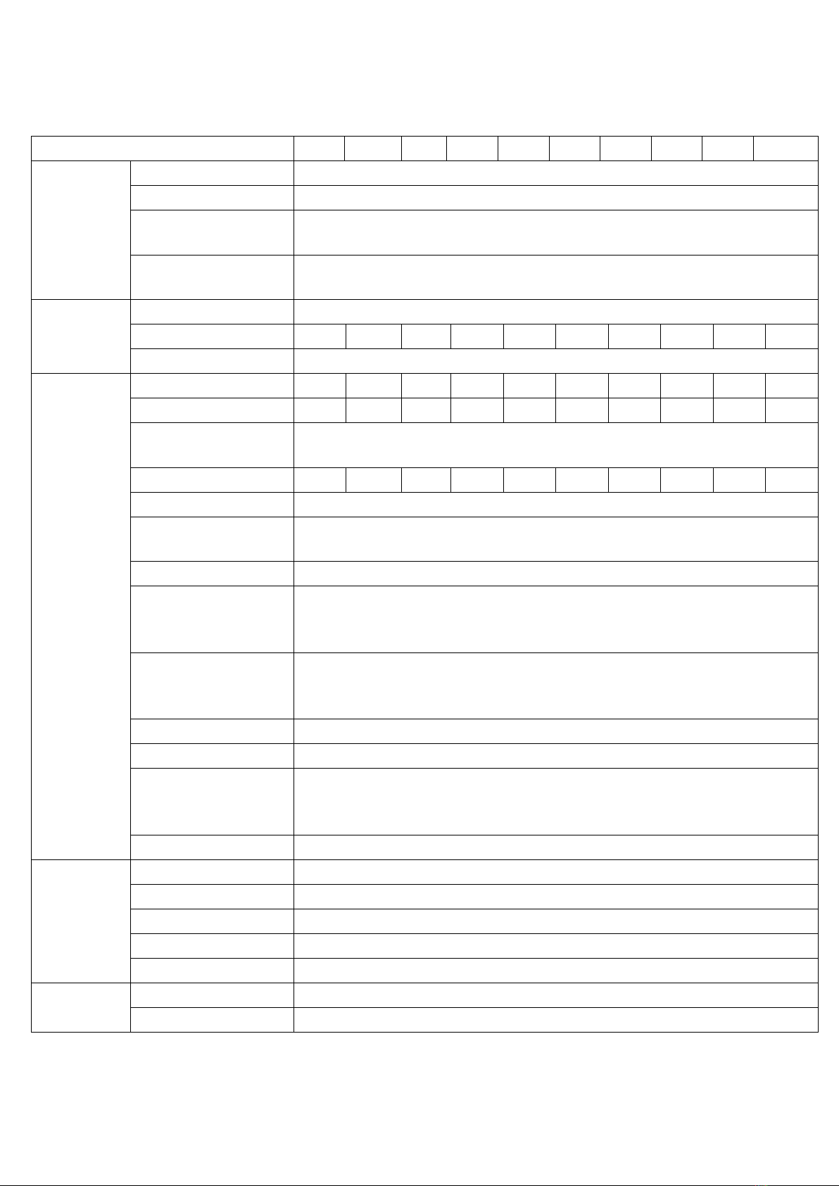
9. SET-IVS9000 Series Model Technical Specifications
Chart 2:SET-IVS9000 Series Model Technical Specifications
Technical Specifications (VA)
0.5K
1K
2K
3K
4K
5K
6K
7K
8K
10K
DC INPUT
Input Voltage(Vdc)
See chart3
Input current(A)
See chart3
Input range of
Voltage(Vdc)
See chart3
Reflected Noise
Current
≤10%
AC Bypass
Bypass Volt(Vac)
260V-180V(±10V)
Input Current(A)
2.3
4.5
9.1
13.6
18.2
22.7
27.3
31.8
36.4
45.4
Transfer Time(ms)
≤5ms
AC
OUTPUT
Rated Capacity(VA)
500
1K
2K
3K
4K
5K
6K
7K
8K
10K
Output Power(W)
400
800
1600
2400
3200
3500
4200
4900
5600
7000
Voltage and
Frequency
220Vac,50HZ
Output Current(A)
1.8
3.6
7.2
10.8
14.5
16
19.1
22.3
25.4
31.8
Voltage Precision(V)
220±1.5%
Frequency Precision
(Hz)
50±0.1%
Output wave
Pure Sine Wave
Wave Distortion
(THD)
(Resistant Load)
≤3%(Linear Load)
Dynamic Reaction
Time
(Load 0←→100%)
5%((load 0←→100%)
Power Factor(PF)
0.8/0.7
Overload
120%,30s
Inversion Efficiency
(80% Resistant
Load)
≥85%
Transfer Time(ms)
≤5ms
ENVIRONM
ENT
Isolation(IN/OUT)
1500Vac,1min
Noise(1m)
≤40dB
Temperature
-20℃~+50℃
Humidity
0~90%,Non-condensing
Sea Level(m)
≤2000
SHOW
LCD
Input and Output Voltage, Frequency, Output Current, Temperature
Inverter status
Power normal, Inverter normal, battery voltage, output overload

11
MECHANIC
AL
Standard rack
(D×W×H)( mm)
See SET-IVS9000 Series Mechanical properties
Weight(Kg)
See SET-IVS9000 Series Mechanical properties
Protection Function
Input Low/High Voltage;Output Overload/Shortage;
Reversed Input Connecting Protection
Note: Rated output power error: 500VA to ±50W; 1-5KVA to ±100W; 6KVA to ±
200W
Chart 3:SET-IVS9000 Series inverter input DC voltage, current, efficiency (error:
±2V/±2%)
SET12 Series
SET24 Series
SET48 Series
SET110 Series
SET220 Series
Rated
input
voltage
(Vdc)
12V
24V
48V
110V
220V
DC
input
voltage
range
(Vdc)
Turn-off voltage
10V—15V
Turn-off voltage
20V—30V
Turn-off voltage
40V--60V
Turn-off voltage
90V—139V
Turn-off voltage
180V--275V
Turn-on voltage
11V—14V
Turn-on voltage
22V—28V
Turn-on voltage
45.5V—57V
Turn-on voltage
104V—131V
Turn-on voltage
208V—260V
Rated
input
current
(A)
500VA
42
500VA
21
500VA
10
500VA
5
500VA
2
1KVA
83
1KVA
42
1KVA
21
1KVA
9
1KVA
5
--
--
2KVA
83
2KVA
42
2KVA
18
2KVA
9
--
--
2.5KVA
104
3KVA
63
3KVA
27
3KVA
14
--
--
--
--
4KVA
83
4KVA
36
4KVA
18
--
--
--
--
5KVA
104
5KVA
45
5KVA
23
--
--
--
--
6KVA
125
6KVA
55
6KVA
27
--
--
--
--
7KVA
146
7KVA
64
7KVA
32
--
--
--
--
8KVA
167
--
--
8KVA
36
--
--
--
--
10KVA
210
--
--
10KVA
45
Note: 1) When tested by using different instruments, the test range may have some deviation.
2) Current from this form is only for distribution size reference.
Explanation:
1) In order to protect the battery, only when the battery voltage was in tun-on voltage range, the
inverter can normal boot.
2) Boot into working condition, as long as the battery voltage in the turn-off voltage range, the
inverter can work. When the battery voltage falls the limit of turn-on voltage, there will be low
voltage alarm; when it goes on fall to the limit of turn-off voltage, inverter shutdown.

12
10.SET-IVS9000 Series Mechanical properties
Figure 1:0.5K-3KVA Mechanical info(2U/19 Inch Rack Type LCD Panel)
Machine Model: 500VA Size: 482*375*88 (W*D*H) Weight: 5Kg
1KVA Size: 482*375*88 (W*D*H) Weight: 8Kg
2KVA Size: 482*375*88 (W*D*H) Weight: 8Kg
3KVA Size: 482*375*88 (W*D*H) Weight: 10Kg
Figure 2:4K-5KVA Mechanical info(2U/19 Inch Rack Type LCD Panel)
Machine Model: 4KVA Size: 482*386*88 (W*D*H) Weight: 11Kg
5KVA Size: 482*386*88 (W*D*H) Weight: 11Kg

13
Figure 3:6K-10KVA Mechanical info (4U/19 Inch Rack Type LCD Panel)
Machine Model: 6KVA Size: 482*400*176 (W*D*H) Weight: 15Kg
7KVA Size: 482*400*176 (W*D*H) Weight: 15Kg
8KVA Size: 482*400*176 (W*D*H) Weight: 17Kg
10KVA Size: 482*400*176 (W*D*H) Weight: 17Kg
Fingure 4: 48Vdc-10KVA Mechanical info(8U/19 Inch Rack Type LCD Panel)
11. Accessory
1)Terminal: 5pcs;
2)A technical manual (including quality assurance);

14
3)Mounting holes screws: 4 pcs, factory inspection report.
12. Note
Please understand that due to constantly update the product, the content of this
document does not exactly match the actual product. For product updates, please
contact us.
Chart 4: Inverter common fault analysis table
Fault type
Symptom
Fault Analysis
Determine the point of failure
Fault handling
Note
Boot failure
Unbootable
Reverse the positive
and negative
Check first before wiring correct
negative DC input, high-potential pick
"+" pole, low potential connection "-"
pole
Re-wiring after
confirm the
positive and
negative
Low voltage DC
power
Measure the both ends of the terminal
voltage in DMMs DCV, check whether
the voltage is higher than the turn-on
voltage
Boot after
charging the
battery voltage
to get the
turn-on voltage
Work failure
After working
for some
time machine
no output
Low or high voltage
inverter protection;
Overload protection
Disconnect the load,and test
if it can work without load and each
voltage
is normal,etc..
Consult factory
technician
Power switch
failure
Not switch
Power voltage is too
high or too low
Use a multimeter inverter AC input
voltage to see if the operating range
Switch after
power voltage
stability
Low-voltage inverter
shutdown protection
After the low-voltage inverter
shutdown, no switching to AC
Switch after
inverter
working
Output Fault
No output
Machine protection
High voltage, low voltage,
over-temperature, overloading, etc.
Consult factory
Communication
failure
Unable to
communicate
Whether a wrong
communication port
Check whether to choose the right
means of communication (RS232 or
485)
Choose the
right
communication
Communicati
on is
unstable
Whether the
communication line
is too long
Check whether communication lines,
wire and panels baud rate match
Replacing UTP
or reset the
baud rate
Note: When testing, please combine this chart and chart 1 to judge.
15
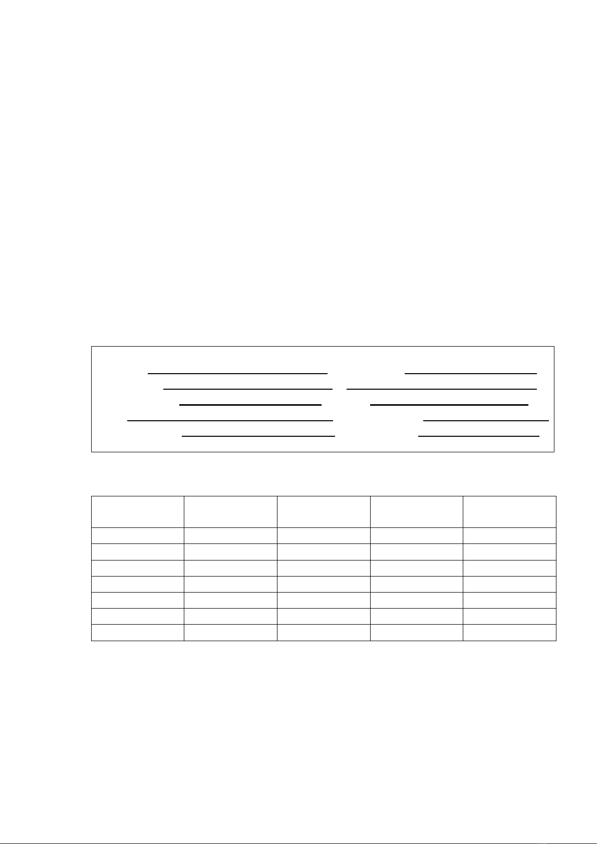
Quality assurance card
Before leaving the factory, we ensure the sine wave inverter quality is excellent and it must be
strictly checked. The company assures customers a good machine performance, mechanical integrity.
One-year free warranty service, warranty are as follows:
(1) In one-year warranty period, if mechanical damage and failure occure, we will provide free repair
and replacement parts, when the company's technical staff confirmed that the it is occurring
under normal use. Damaged parts should be returned to the Company.
(2) As stated in this warranty card machines in the following cases, the warranty period will expire
automatically:
(a)The change of company trademarks;
(b) Due to misuse, negligent use, irresistible factors that cause damage;
(c) Not follow installation instructions that provided by the original installation to install.
(3) Please present this card, show the card and purchase receipt (invoice)to technicians when it need
to be repaired.
User information
User units Contact Person
User address Tel
Distribution Unit Zip code
Model machine numbers
Date of purchase Handling person
Maintenance record sheet
Date
Repair types
Abstract
Maintenance
staff
User Signature
Note: Please immediately send a copy with the official seal to the marketing
department after fill in the user information.
Table of contents


