LE10XRT Due to continuing product development, specications are subject to change without notice. © 2016 RenewAire LLC
138276_000 LE10XRTMan_Dec15.indd 12/2015 www.renewaire.com Page 6
VIBRATION ISOLATION
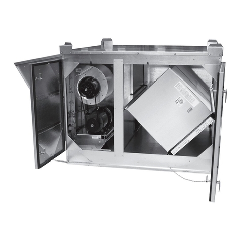
LE-Series units are standardly supplied with vibration isolators
for the motor/blower assemblies. Both neoprene and spring
vibration isolators are offered. Spring isolators are externally
adjustable with elastomeric snubbers. The standard isolators are
not seismic-rated. See table for additional technical information.
Blower discharges are connected to the Outlets with exible duct
to minimize vibration bypass around the isolators.
Possible damage to equipment if the motor/blower
assembly vibration isolators are used with whole-unit
spring isolation, such as isolation curbs. If an isolation
curb is to be used, the LE- unit must be special-ordered
with no internal vibration isolators.
DUCT CONNECTIONS
Any duct connections to the sides of the unit are equipped with
double-anged duct connections. These allow for connection of ducts
insulated on the inside or the outside, or for installation of lined duct.
Connect ducts to these anges with standard S-Slips. Seal duct
exterior to the unit to keep the weather out.
Any duct connections to the bottom of the unit are made to the
duct supports on the optional roof curb. The sizes of the duct
openings in the curb allow for 1” of insulation on duct in addition
to duct ID sizes shown on dimension drawings, page 5.
If the inside ducts run through un-conditioned spaces,
they must be insulated, with a sealed vapor barrier on
both inside and outside of insulation.
Any ductwork that is exposed to the weather must be
properly insulated and weather-proofed.
SOUND ATTENUATION
Outside the building:
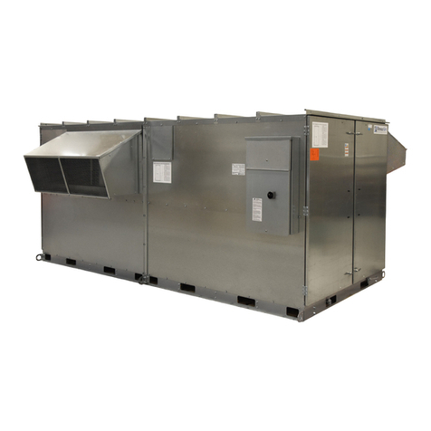
The exhaust hood is the primary source of noise outside the
building. When practical, orient the exhaust air hood to point
away from houses or public areas.
At the Curb:
Cut the holes in the roof deck to t closely around the duct(s) passing
through the roof deck. Seal all gaps around the duct(s) at the roof deck.
Duct Stiffness:
Make sure the ductwork at the unit outlets is stiff enough to
resist the exure and resulting booming associated with system
start-up and shut-off, as well as the turbulent ow conditions at
the blower outlets.
In general, provide smooth transitions from the ERV’s outlets to
the duct. The ducts connecting to the outlets should be straight
for a sufcient distance, with gradual transitions to the nal duct
size. These guidelines are consistent with SMACNA recommended
duct layout practices for efcient and quiet air movement.
Follow SMACNA guidelines.
Radiated Noise:
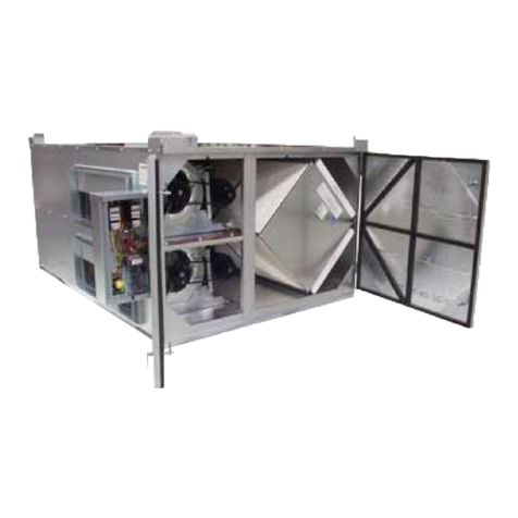
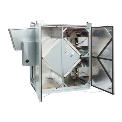
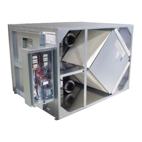
The LE10XRT is insulated with high-density berglass. This provides
signicant attenuation of radiated sound from the unit itself.
The outlet ducts can be signicant sources of radiated sound
as well. The FA duct should be insulated for sound control. This
insulation should start at the unit. At a minimum the rst ten feet
of duct should be insulated. All parts of the FA and RA ducts located
in a mechanical space with noise-generating equipment also should
be insulated for sound control, both to minimize sound radiation out
of the FA duct, and also to control sound radiation into both ducts.
SETTING AND INSTALLING THE UNIT
ON THE CURB OR EQUIPMENT RAILS
Install ducts that pass through the curb before setting the unit.
Install optional Curb Clips to the Curb before setting the unit.
See separate Shipping &Rigging Manual.
VIBRATION ISOLATOR SPECIFICATIONS, DESIGN LOADS
AND DISTURBING FREQUENCIES
Isolator Type NEOPRENE SPRING
Isolator Location Back/Motor
End
(Black)
Blower
Front End
(Blue)
Back/
Motor End
(Orange)
Blower
Front End
(Brown)
Quantity 4 2 4 2
Rated Max Load (lbs) 170 135 225 125
Rated Max Deection (in.) 0.50 0.50 1.30 1.30
Spring Rate (LB/IN) 340 270 173 96
Design Load (LB each)* 95-111 75-90 95-111 75-90
Final Height Not adjustable Adjust to 4.2”
Disturbing Frequencies: 60 Hz (power line frequency)
29.0-29.3 Hz (motor speed), 10-20 Hz (blower speed).
*Exact Design Load varies depending on motor HP

