Renfroe WHSR Installation guide

WARNING:
Before putting tool in service,
take to your immediate
supervisor.
Model WHSR Clamp
Application, Operation and Maintenance Manual
OM 211-WHSR
RENFROE

This Operator’s Manual covers the Application, Operation
and Maintenance of this RENFROE product. Operator’s
Manuals for other current RENFROE products are available
upon request. Direct Requests to J.C. Renfroe & Sons, Inc.,
Jacksonville, Florida 32201.
Operators
Manual
J.C. RENFROE & SONS,
INCORPORATED
of Jacksonville, Florida, has
been an international leader
in the manufacture and mar-
keting of Lifting Clamps for
over fifty years. RENFROE
products are manufactured
in Jacksonville, Florida. A
worldwide network of stock-
ing distributors provides a
readily available source of
supply and service.
J.C. RENFROE & SONS,
INCORPORATED
Jacksonville, Florida 32201
Telephone: 904/356-4181
Toll Free: 1-800-874-8454
Fax: 904/354-7865
www.jcrenfroe.com
Copyright © 2001 J.C. Renfroe & Sons, Inc.

THIS PUBLICATION SUPERSEDES ALL
PREVIOUSLY PUBLISHED AND/OR DISTRIBUTED
INFORMATION BY MANUFACTURER AND/OR ITS
DISTRIBUTORS WITH RESPECT TO APPLICABLE
RENFROE PRODUCTS AND SUBJECT MATTER
DESCRIBED OR CONTAINED HEREIN.
NOTICE OF EXCLUSION OF WARRANTY
RENFROE HAS HEREIN SET FORTH IN
CONSPICUOUS LANGUAGE AN EXCLUSION OF
ANY WARRANTY EITHER EXPRESSED OR
IMPLIED, WHICH IS NOT SPECIFICALLY AND
PARTICULARLY CONTAINED HEREIN. PLEASE
REFER TO THAT STATEMENT FOR
REPRESENTATIONS AND WARRANTIES OF
PRODUCTS MANUFACTURED BY J.C. RENFROE &
SONS, INC.
WARNING:
Prior to selection, operation and/or maintenance
of RENFROE products, read and understand the infor-
mation provided in this manual.
The understanding and use of the Definitions are
important in determining the limitations and proper appli-
cation of RENFROE products.
Failure to review and utilize recommended appli-
cations, operation and maintenance instructions may
result in serious injury to operator and others.


OPERATING AIDS
(DO’S AND DON’TS)
1. DO read and understand the Operators Manual before using the clamp
2. DO Consult Operator’s Manual or RENFROE when in doubt.
3. DON’T Lift over workmen DON’T lift over Safety Areas or personnel.
4. Do attend a factory training class for establishing proper use of Renfroe
Products.
5. DO Lock clamp closed before lifting load. DON’T lift with lock in open or
“Lock Open” position.
6. DON’T Use a connection that may release the clamp.
7. DON’T attach clamp directly to crane hook. DO use a flexible connection
between crane and clamp shackle. DON’T use heavy flexible connection.
8. DO use correct clamp for job. DON’T use large capacity clamps to lift light
loads.
9. DO Use an adequate number of clamps to balance load. DON’T lift loads
that are not balanced.
10. DO Use clamps within their rated capacity. DON’T overload clamps
11. DO Inspect clamp before each lift, follow inspection and maintenance in-
structions outlined in this manual and use RENFROE replacement parts to
assure proper operation of the clamp
12. DON’T Use clamp that has been overloaded. DO refer to pre-lift inspection
in Operators Manual
13. DON’T Side load with a straight shackle clamp. DON’T lift from side with
vertical clamp
14. DON’T Misuse. DON’T lift plate from bottom of plate stack.
15. DON’T Rush. DON’T lift more than one plate at a time with a vertical clamp.
16. DON’T Improvise. Always use correct clamp for job. DON’T lift plate hori-
zontally with a vertical lift only clamp.
17. DON’T Alter clamp. DON’T grind, weld or modify the clamp in any manner.

DEFINITIONS
VERTICAL LIFT: The lifting of a single
plate or member in which the lifting
force exerted by the rigging is directly
above and in line with the lifting shackle
as shown in the illustration below.
VERTICAL TURN/LIFT: A vertical turn/
lift clamp is a vertical lifting clamp spe-
cifically intended to turn a single plate or
member thru a ninety degree (90°) arc
and back to vertical thru the same nine-
ty degree (90°) arc or from horizontal to
vertical to horizontal thru a one hundred
and eighty degree (180°) arc. Refer to
Application Section of specific Turn/Lift
clamps for further detail. During the
turning operation the edge of the plate
opposite the edge to which the clamp is
attached should always be in contact
with a supporting surface such as a fac-
tory floor and the load on the clamp not
exceed one half rated capacity of
clamp—refer to illustrations shown be-
low.
HORIZONTAL LIFT: Clamps (used in
pairs or multiples) are attached to the
side edges of a plate or bundle of
plates positioned horizontally to the
floor level. The rigging attached to
clamps is generally multi-legged slings
with the connecting point of the slings
being approximately centered between
the distance separating the clamps.
Refer to illustrations shown below.
WARNING: The capacity of all hori-
zontal clamps is based on a sling
angle of sixty degrees (60°). See
illustration below. Sling angles less
than sixty degrees (60°) increase the
load exerted on the clamps, Never
exceed the rated capacity of a single
clamp.
STEEL PLATES: Unless otherwise
specified, lifting clamps are manufac-
tured to handle hot-rolled steel plates
whose Brinell Hardness does not ex-
ceed 300. WARNING: Do not lift
plates with coatings or mill scale
that prevent the gripping surfaces of
the clamp from making positive con-
tact with the base metal.
For applications not covered by the
above information, secure written rec-
ommendations from RENFROE.
FINISHED AND POLISHED PLATES:
Steel plates in this category have other
than hot-rolled surfaces such as stain-
less steel, etc., are generally handled
using non-marring clamps incorporat-
ing smooth gripping surfaces.
WARNING: For applications using
clamps with serrated gripping sur-

faces on finished or polished plates,
secure written recommendations
from RENFROE.
STRUCTURAL MEMBERS—
FABRICATED SECTIONS: Unless
otherwise specified, clamps described
as capable of handling structural mem-
bers and fabricated sections are limited
to hot-rolled steel whose Brinell Hard-
ness does not exceed 300. WARN-
ING: For applications not covered
by the above information, secure
written recommendations from REN-
FROE.
RATED CAPACITY: The rated capaci-
ty of a RENFROE product is based on
the product being in “new or as new”
condition and represents the maximum
load the product is to be subjected to
when utilized in the manner described
in this manual. Wear, misuse, abuse
and other factors relating to usage may
reduce the rated capacity. Shock load-
ing and the factors listed must be taken
into consideration when selecting a
RENFROE product for a given applica-
tion.
PLATE THICKNESS: The minimum
and maximum plate thickness a clamp
specified for handling plates is capable
of lifting. WARNING: Never use a
clamp for lifting a plate where the
plate thickness is less than or great-
er than the minimum and maximum
stenciled on the clamp.
JAW OPENING: The minimum and
maximum thickness of a member of
clamp specified as having a JAW
OPENING is capable of handling.
WARNING: Never use a clamp on a
member whose thickness is less
than or greater than the range of jaw
opening stenciled on the clamp.
OPERATING TEMPERATURES: Un-
less specified under the Application
Section of the individual model, the
approved operating temperature of
RENFROE clamps is from zero de-
grees Fahrenheit (-18 Celsius) to a
maximum of 200 degrees Fahrenheit
(+93 degrees Celsius). The minimum
and maximum temperatures apply to
both ambient and the material being
handled by the clamp. WARNING:
Secure written authorization from
RENFROE before using clamps in
temperatures other than shown.
“HOT LIFTS”: The Model R and S
clamps are available in modifications
that are capable of making lifts where
the temperatures of the member being
lifted exceeds 200 degrees Fahrenheit
(+93 degrees Celsius). Depending on
conditions a lift may exceed 1000 de-
grees Fahrenheit (538 degrees Celsi-
us). The exact application and temper-
atures of the plates to be handled are
critical in selecting the proper model.
WARNING: Secure written instruc-
tions from RENFROE for all hot lift
applications.
LOCKING CLAMPS: Locking clamps
are divided into the categories listed
below. With the exception of the
“Locking Wedge” and “Locking Screw”
type the purpose of the locks are to
facilitate the attaching and removing of
the clamp from the member being han-
dled.
“LOCK CLOSED” - an overcenter
spring loaded mechanism in which the
spring exerts a force on the gripping
cam when the lock handle is moved to
the “Lock Closed” position. When the

handle is moved to unlocked position
the force exerted by the spring is re-
laxed and the gripping cam may be
retracted by pushing the lifting shackle
into body of clamp. Refer to the Oper-
ation Section of specific models of
“Lock Closed” clamps for additional
details. Typical “Lock Closed” clamps
are Models DG, FR and M.
“LOCK OPEN ONLY” - normally used
on “Hot Lift” clamps and consists of a
manually operated “Lock Stop Pin” that
is inserted when gripping cam of clamp
is retracted and removed when clamp
is positioned on the plate. Tag line
may be used to permit operator to re-
move pin from a greater distance from
clamp. Refer to the Operation Section
of specific model of “Lock Open Only”
clamps for additional details. Typical
“Lock Open Only” clamp is the Model
RO.
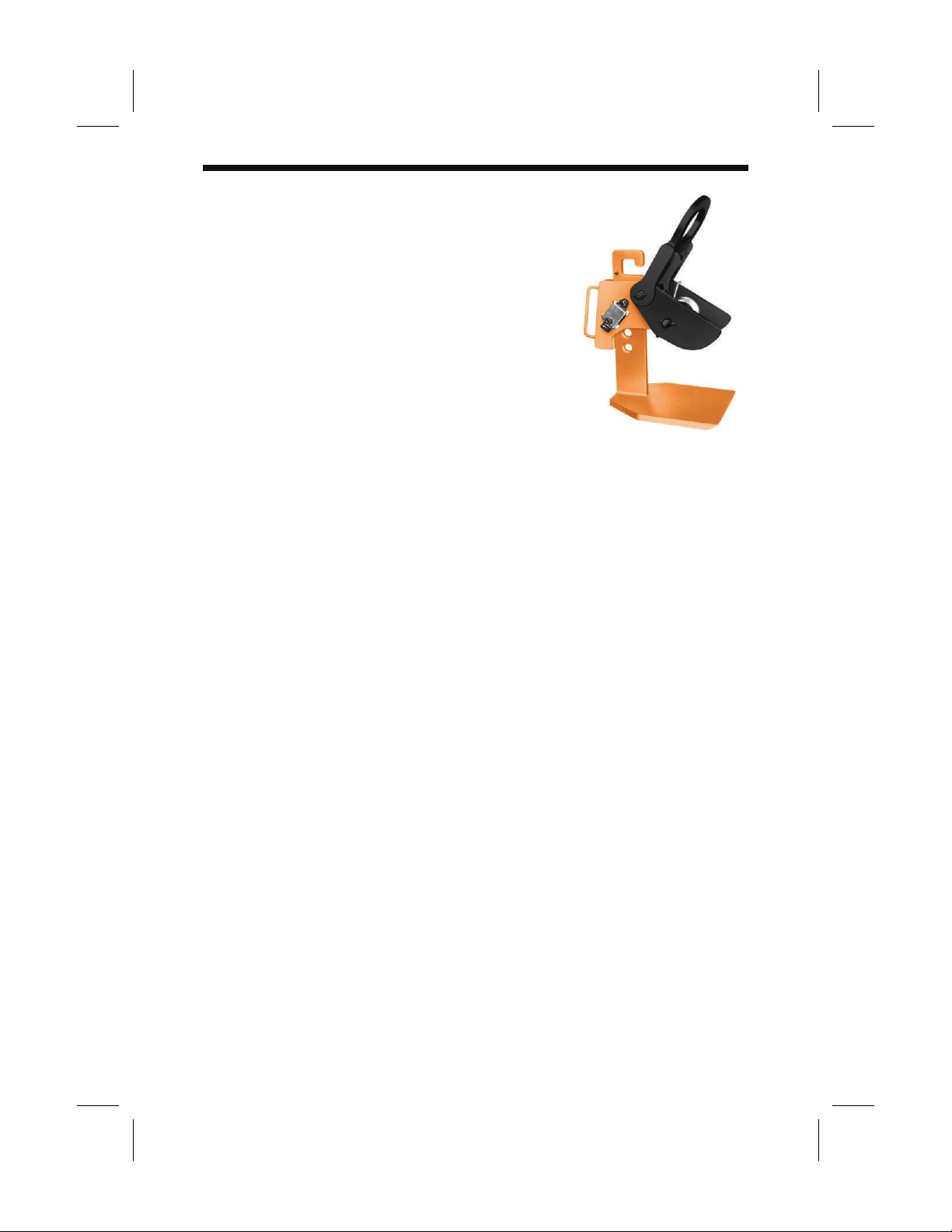
“LOCK OPEN-LOCK CLOSED” - an
over-center spring loaded mechanism
in which the spring exerts a force on
the gripping cam when the lock handle
is moved to the “Lock Closed” position.
When the handle is moved to the “Lock
Open” the gripping cam is maintained
in the retracted position for ease in in-
stalling the clamp on a plate or mem-
ber. The Model FRD contains individu-
al “Lock Open” and “Lock Closed”
mechanisms that must be operated
separately. Refer to the Operation
Section of specific models of the “Lock
Open-Lock Closed” clamps for addi-
tional details. Typical “Lock Open-
Lock Closed” clamps are Models FRD,
R, S, SD, SEA, SX, TL, TLA and the J-
Series.
“LOCKING WEDGE - is a fluted steel
wedge that is driven in place with a
hammer. The body of the wedge is
positioned in a slot in the clamp body
with the fluted edges contacting the
member to which the clamp is being
attached. Refer to Operation Section
of specific models of the “Locking
Wedge” clamps for additional details.
Typical “Locking Wedge” clamps are
Model A1, B1, B2 and PB.
”Locking Screw” - “Lock Screw” clamps
depend on manually adjusting a screw
to hold the gripping surface in place for
lifting and removing the clamp from
member being lifted. Refer to Opera-
tion Section of a specific model of
“Locking Screw” clamps for additional
details. Typical “Locking Screw”
clamps are Models AC, ACP, NM, PC,
SCP and SCPA.
NON-LOCKING: “Non-Locking”
clamps have no mechanisms to aid in
attaching or removing clamp from
member being lifted. It is necessary to
have position of clamp maintained on
the member being lifted until a properly
applied force is exerted to the lifting
shackle. Refer to Operation Section of
specific models of the “Non-Locking”
clamps for additional details. Typical
“Non-Locking” clamps are Model AST,
ASTL, BD, HR, HDR and WHSR.
WARNING: A pointing out and notice
of danger. The purpose of a
“WARNING” is to apprise the operator
and all other affected persons of the
existence of danger of which he should
be but may not be aware and to enable
the operator to protect himself and oth-
ers where applicable against such dan-
ger. An attempt is made herein to
warn against reasonable and reasona-
bly foreseeable danger in the proper
use and possible reasonable misuse of
RENFROE products described in this
manual.

DESIGNATED PERSON — A person se-
lected by the employer or the employer’s
representative as being competent to per-
form those specific duties.
QUALIFIED PERSON — A person who, by
possession of a recognized degree in an
applicable field or certificate of professional
standing, or who, by extensive knowledge,
training, and experience, has successfully
demonstrated the ability to solve problems
relating to the subject matter at hand.

MODEL WHSR
HORIZONTAL LIFTING
NON-LOCKING
Application WHSR
The model “WHSR” is an adjustable, horizontal clamp intended to be
used in pairs, sets of pairs, or in a tripod arrangement for transporting
steel plates in the horizontal position. Refer to Illustrations shown be-
low. In addition to incorporating two gripping cams, the jaw opening
may be adjusted by the positioning of a pin in the body of the clamp.
The gripping cams are spring loaded to remain in the “Open” position
until the load is applied. This feature permits the clamp to be easily
applied and removed from the load. The model “WHSR” is a “Non-
locking” clamp and requires constant tension applied to lifting shackle
throughout the entire operation. Refer to Definitions, Page 2, for ex-
planation of “Non-locking” clamp. Normally furnished with serrated
gripping surfaces, it is available with smooth faced bronze or stainless
steel surfaces to prevent marring when handling polished plates.
For identification of component parts, refer to exploded view of the
clamp located at the end of the Maintenance Section.
WARNING: The rated capacity is based on a sling angle of 60 de-
grees. Refer to Illustration A. Sling angles less than 60 degrees
increase load on clamp. Refer to Operation Section, Step 3, Chart
C, for correct loading of clamp with sling angles less than 60 de-
grees. Sling angles greater than 60 degrees reduces gripping
force. Do not exceed 60 degrees. Always use an adequate num-
ber of clamps to assure a balanced load. Never exceed the rated
capacity of a single clamp. Never use on plate or bundle of plates
that are not able to support themselves without sagging. Refer to
Illustration B. Refer to the sections on operation and mainte-
nance for the approved procedures in the operation and mainte-
nance of this product.


Operation WHSR
Step 1.
Before using any RENFROE clamp, refer to the Application Section to
confirm that the operation to be undertaken is an appropriate applica-
tion for this product.
Step 2.
The model “WHSR”, rated individually, is used in pairs, multiples of
pairs, or tripods.
The “WHSR” has an adjustable jaw opening. When used in pairs or
multiples, set all of the clamps at the same jaw opening whenever pos-
sible or in such a manner that the plates being lifted remain horizontal
and do not tilt.
WARNING: Never exceed the rated capacity of a single clamp.
Step 3.
Select clamp with proper capacity and jaw opening range. Use of sling
angles under 60 degrees increases the load on the clamps. Use Chart
C to determine maximum capacity weight per clamp when using sling
angle less than 60 degrees.
CHART C
WARNING: Always use an adequate number of clamps to assure a bal-
anced load. Never use on plates or bundles of plates that are not able to
support themselves without sagging or stacked without sagging or
stacked without edges being even.
Refer to Illustrations A and B


Step 4.
Inspect clamp before each lift.
WARNING: Do not use if in need of repair.
If in doubt, refer to Maintenance Section for detailed mainte-
nance instructions and exploded view of the clamp for part iden-
tification.
A. Check the clamp to be certain the Identification and
warning tags are present and legible.
B. Do not use the clamp if the tags are missing or illegible
C. Inspect gripping surfaces of cams for wear and defects.
Gripping surfaces must be sharp and free of foreign matter.
D. Inspect condition of body for wear, damage and distortion.
Take particular note of the intersection of the vertical upright
and the footpad.
E. Inspect footpad for distortion of bending indicating the clamp
has been subjected to overloading.
F. Inspect lifting shackle and all pin holes for wear and elonga-
tion.
G. Inspect cam spring for distortion and damage.
H. Inspect adjustable bar pin for wear and damage.
I. Inspect safety pin assembly for wear and damage. Spring
must be in place. Safety pin assembly must engage adjust-
ing bar pin a firm manner holding it securely in place.
J. Inspect lifting shackle for wear and damage.
K. Remove any clamp from service in need of repair.

Step 5.
The clamp is a component of the rigging used in the lifting or transport-
ing of plates. It is important to use safe and adequate rigging. Each
clamp is manually held in place until the gripping mechanism of the
clamp is activated by a force applied to the lifting shackle.
WARNING: Improper or excessively heavy rigging may interfere
with the operation of the clamp and its ability to maintain proper
position on the plate. Never attach crane hook directly to the
clamp—always use a flexible sling between crane hook and
clamp.
The clamp springs are intended to hold the cams in the “Open” posi-
tion to facilitate mounting the clamps on the plates.
Step 6.
Adjust clamp jaw opening by positioning the adjusting bar pin accord-
ing to thickness of load the be lifted. Refer to Photograph F and
Charts D and E for proper positioning of adjusting par pin.


Step 8.
Assemble the clamps on the plates so the edges of the plates are posi-
tioned the full depth of the clamp footpads. Refer to Illustration A, Step
3 and Photograph H.
Position the clamps so the direction of force applied by the crane is in
line with the lifting shackles.
WARNING: Never exceed ten degrees side-loading.
Refer to Photographs J, K and L.

Step 9.
Each person must make certain the gripping cams and lifting pads are
fully in contact with the plates and not partially on and off the edge of
the plates.
Step 10.
Each person must hold a clamp in place until lifting sling is tight
enough to maintain clamps’ position on plates.
WARNING: A constant force must be maintained on the lifting
shackles throughout the entire operation.
Refer to Photograph M.
Step 11.
Commence lift.
WARNING: The operator should position himself away from and
fully clear of the member to be lifted. Do not commence lift until
all personnel are clear of the area of the lift. Never stand under or
near a member being lifted, lowered or moved.
Refer to Photograph N.

Step 12.
To remove clamps—after the plates are fully supported and at rest in a
stable position, relax lifting force on shackles. Remove clamps from
the plates.
Step 13.
Inspect clamp. Remove from service if in need of repair.
WARNING: In the event the stenciling is worn and not legible or
the tag containing the model, capacity or other pertinent infor-
mation is missing—do not use clamp until it has been properly
labeled. Renfroe will replace tags at not charge upon request.
For identification of component parts, refer to the exploded view of
clamp located after Step 12. Inspection Kits are available to no charge
upon request from the distributor or RENFROE. Kit contains:
Table of contents
Other Renfroe Tools manuals