Renke RS-FX Series User manual

Wind direction transmitter instruction manual (analog type)
Shandong Renke Control Technology Co., Ltd. www.renkeer.com
1
RS-FX-*
Wind direction
transmitter
Instruction Manual
(Analog)
Document version:V2.1

Wind direction transmitter instruction manual (analog type)
Shandong Renke Control Technology Co., Ltd. www.renkeer.com
2

Wind direction transmitter instruction manual (analog type)
Shandong Renke Control Technology Co., Ltd. www.renkeer.com
3
Table of Contents
1. product description..................................................................................................................4
2. product model..........................................................................................................................5
3. Equipment installation instructions.........................................................................................5
4. Calculation method................................................................................................................. 8
5. Common problems and solutions............................................................................................8
6. contact details..........................................................................................................................8
7. Document history..................................................................................错误!未定义书签。
8. Dimensions..............................................................................................................................9
Attachment: On-site drilling instructions................................................. 错误!未定义书签。

Wind direction transmitter instruction manual (analog type)
Shandong Renke Control Technology Co., Ltd. www.renkeer.com
4
1. product description
1.1 product description
RS-FX- * wind direction transmitter, compact and lightweight, easy to carry and assemble. The
new design concept can effectively obtain the wind direction information. The housing is made of
high-quality aluminum alloy profile, and the exterior is plated and sprayed with plastic. Features
such as erosion can ensure long-term rust-free use of the transmitter. Colleagues cooperate with
the internal smooth bearing system to ensure the accuracy of information collection, and use
traditional analog signals (4-20mA, 0-10V, 0- 5V) for data output. It is widely used in wind
direction measurement in greenhouses, environmental protection, weather stations, ships,
terminals, breeding and other environments.
1.2 Features
1.Range: 8 directions
2. Anti-electromagnetic interference treatment
3. Imported high-performance bearings, small rotation resistance and accurate measurement
4.All-aluminum housing, high mechanical strength, high hardness, corrosion resistance, no rust,
can be used outdoors for a long time
5. The equipment structure and weight are carefully designed and distributed, the moment of
inertia is small, and the response is sensitive
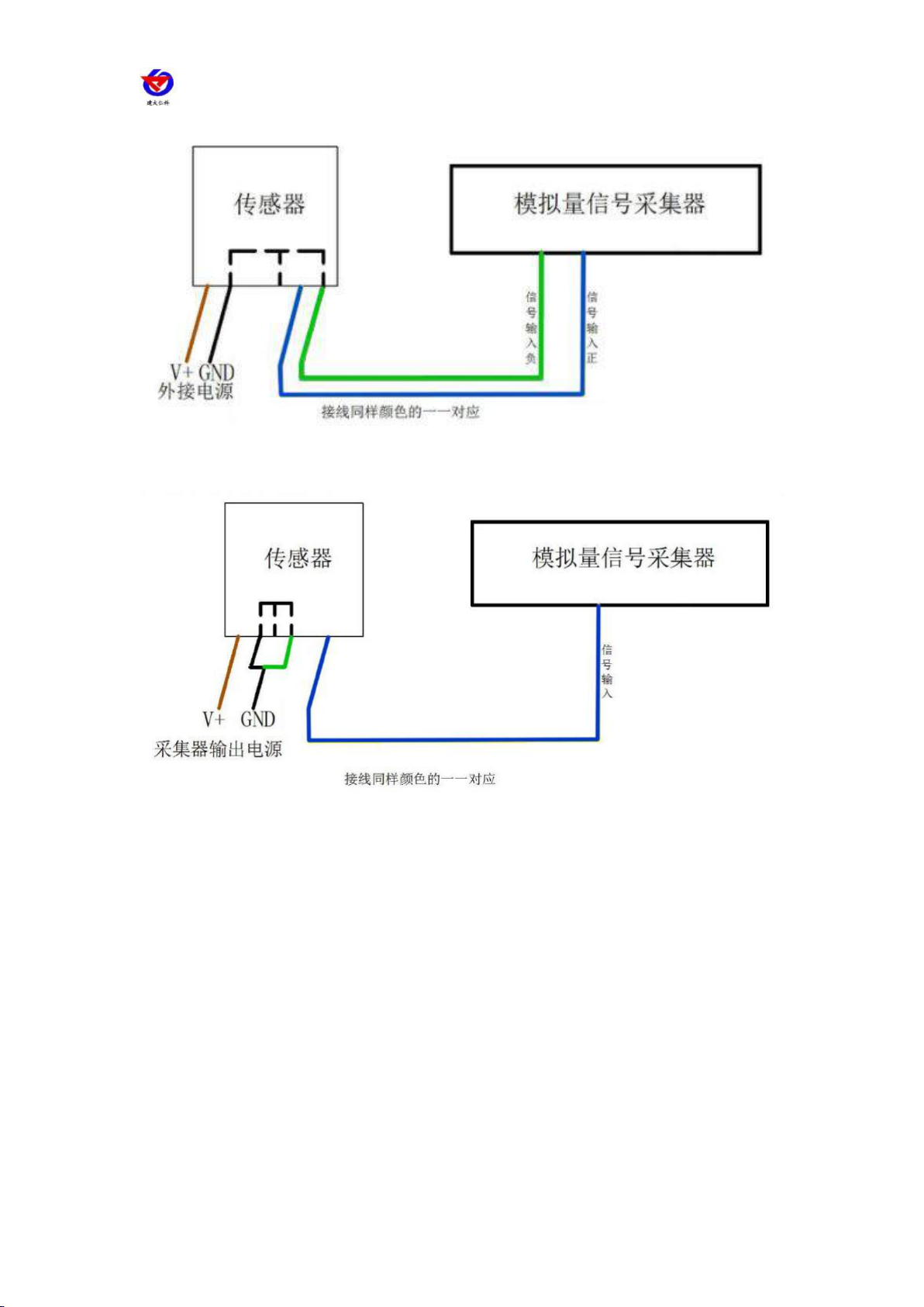
6. It can be applied to both four-wire system and three-wire system.
1.3Main Specifications
DC powered (default)
10~30V DC
Maximum power
consumption
Current output
1.2W
Voltage output
1.2W
Transmitter circuit operating
temperature
-40℃~+60℃,0%RH~80%RH
Measuring range
8 directions
Dynamic response time
≤0.5s
output signal
Current output
4~20mA
Voltage output
0~5V/0~10V
load capacity
Voltage output
Output resistance≤250Ω
Current output
≤600Ω

Wind direction transmitter instruction manual (analog type)
Shandong Renke Control Technology Co., Ltd. www.renkeer.com
5
2. product model
RS-
Company code
FX-
Wind direction transmitter
I20-
4~20 mA current output
V05-
0~5V voltage output
V10-
0~10V voltage output
3. Equipment installation instructions
3.1 Check before equipment installation
1.Transmitter equipment
2.4 mounting screws
3. Qualification certificate, warranty card, wiring instructions, etc.
3.2 wiring
3.2.1: Power wiring
Wide voltage 10 ~ 30V DC power input. For 0-10V output type equipment, only 24V power
supply can be used。
3.2.2:Output interface wiring
Adapt to both three-wire and four-wire。
3.2.3: Electrical wiring
3.3Examples of wiring methods
Thread color
Description
power supply
brown
Power supply
black
Negative power
Output
blue
Positive wind direction signal
green
Negative wind direction signal

Wind direction transmitter instruction manual (analog type)
Shandong Renke Control Technology Co., Ltd. www.renkeer.com
6
Four-wire system connection diagram
Three-wire connection method
3.4Installation method
It adopts flange installation and threaded flange connection to firmly fix the lower pipe of the
wind direction sensor to the flange. The chassis is Ø65mm. Four Ø6mm mounting holes are
opened on the circumference of Ø47.1mm. Use bolts to fix it tightly on the flange. The bracket
keeps the entire set of instruments at the optimal level to ensure the accuracy of the wind direction
data. The flange connection is easy to use and can withstand large pressures.

Wind direction transmitter instruction manual (analog type)
Shandong Renke Control Technology Co., Ltd. www.renkeer.com
7
3.5Precautions
1. The user is not allowed to dismantle by himself, nor touch the sensor core, so as not to cause
damage to the product.
2. Try to stay away from high-power interference equipment to avoid inaccurate measurements,
such as inverters, motors, etc. When installing and removing the transmitter, you must first

Wind direction transmitter instruction manual (analog type)
Shandong Renke Control Technology Co., Ltd. www.renkeer.com
8
disconnect the power supply. Water entering the transmitter can cause irreversible changes.
3. Prevent chemical reagent, oil, dust and other direct damage to the sensor, do not use it for a
long time in the environment of condensation, extreme temperature, and prevent cold and heat
shock.
4. Calculation method
4-20mA output comparison
table
0-10V output comparison table
0-5V output comparison table
output value
(mA)
Correspondin
g wind
direction
Output value
(V)
Correspondin
g wind
direction
Output value
(V)
Correspondin
g wind
direction
≈4
North wind
≈0
North wind
≈0
North wind
≈6.2857
Northeast
wind
≈1.4286
Northeast
wind
≈0.7143
Northeast
wind
≈8.5714
Dongfeng
≈2.8571
Dongfeng
≈1.4286
Dongfeng
≈10.8571
Southeast
wind
≈4.2857
Southeast
wind
≈2.1429
Southeast
wind
≈13.1429
south wind
≈5.7143
south wind
≈2.8571
south wind
≈15.4286
Southwest
wind
≈7.1429
Southwest
wind
≈3.5714
Southwest
wind
≈17.7143
Westerly
≈8.5714
Westerly
≈4.2857
Westerly
≈20
Northwest
wind
≈10
Northwest
wind
≈5
Northwest
wind
5. Common problems and solutions
Symptom: No output or output error
possible reason:
1) PLC calculation error caused by incorrect range measurement. Please refer to the technical
specifications in Part 1 for the measurement range.
2) The wiring method is incorrect or the wiring sequence is wrong.
3) The power supply voltage is incorrect (24V power supply for 0-10V models).
4) The distance between the transmitter and the collector is too long, causing signal disturbance.
5) The PLC acquisition port is damaged.
6) The equipment is damaged.
6. Contact
Shandong Renke Control Technology Co., Ltd.
Address: 2 / F, East Block, Building 8, Shun Tai Plaza, High-tech Zone, Jinan City, Shandong
Province
Post code: 250101
Phone: 400-085-5807
Website: www.renkeer.com
Cloud platform address: en.0531yun.cn Or: eniot.0531yun.cn

Wind direction transmitter instruction manual (analog type)
Shandong Renke Control Technology Co., Ltd. www.renkeer.com
9
Web QR:
7. Document history
V1.0 document creation.
V2.0 documentation update.
V2.1 Corrected mounting hole size.
8. Dimensions
Attachment: On-site drilling instructions

Wind direction transmitter instruction manual (analog type)
Shandong Renke Control Technology Co., Ltd. www.renkeer.com
10
Table of contents
Other Renke Transmitter manuals
Popular Transmitter manuals by other brands

Emerson
Emerson Rosemount TCL user manual

BWI Eagle
BWI Eagle AIR-EAGLE XLT Product information bulletin

ABB
ABB Industrial IT enabled 2600T Series Operating instruction

Sensor Electronics
Sensor Electronics SEC 3100 Instruction and operation manual

Rotronic
Rotronic HygroClip IC-1-EX operating instructions

RKI Instruments
RKI Instruments 65-2641RK-05-04 Operator's manual

AVR
AVR 3004/001 Installation, operation and maintenance manual

Huba Control
Huba Control 699 Mounting instructions

Infineon
Infineon WLC1150 user guide

Honeywell
Honeywell ADEMCO 5817CBXT installation instructions

Nokeval
Nokeval MTR265B user manual

BWI Eagle
BWI Eagle AIR-EAGLE SR PLUS 36-1400-120VAC Product information bulletin