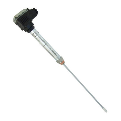
GESTRA NRGT 26-2 User manual

Original Installation &
Operating Manual
EN
English
Level Transmitter
NRGT 26-2
NRGT 26-2s
819876-00

2NRGT 26-2, NRGT 26-2s - Installation & Operating Manual - 819876-00
Contents
Content of this Manual................................................................................................................................... 4
Scope of delivery/Product package............................................................................................................... 4
How to use this Manual.................................................................................................................................. 5
Illustrations and symbols used...................................................................................................................... 5
Hazard symbols in this Manual...................................................................................................................... 5
Types of warning ............................................................................................................................................ 6
Specialist terms/Abbreviations...................................................................................................................... 7
Usage for the intended purpose..................................................................................................................... 8
Applicable directives and standards...........................................................................................................8
Admissible system components, dependent on the required safety level....................................................9
Improper use .................................................................................................................................................. 9
Basic safety notes ........................................................................................................................................ 10
Required personnel qualifications............................................................................................................... 11
Notes on product liability............................................................................................................................. 11
Functional safety, safety integrity level (SIL) .............................................................................................. 12
Check the secure current output regularly................................................................................................12
Reliability data to EN 61508 ......................................................................................................................... 13
Function ........................................................................................................................................................ 14
Technical data .............................................................................................................................................. 16
Name plate/identification of NRGT 26-2...................................................................................................... 19
Name plate/identification of NRGT 26-2s.................................................................................................... 20
Factory settings............................................................................................................................................ 21
Overall view of the NRGT 26-2 ..................................................................................................................... 22
Overall view of the NRGT 26-2s ................................................................................................................... 23
Dimensions of the NRGT 26-2 ...................................................................................................................... 24
Dimensions of the NRGT 26-2s .................................................................................................................... 25
Preparing for installation ............................................................................................................................. 26
Installation.................................................................................................................................................... 27
Installing the NRGT 26-2..........................................................................................................................28
Sealing surface dimensions of the NRG 26-2 ...........................................................................................28
Example ..................................................................................................................................................28
Installing two level electrodes in a flange.................................................................................................29
Installing the NRGT 26-2s........................................................................................................................29
Installation example with dimensions for the NRGT 26-2 .......................................................................... 30
Positioning the terminal box........................................................................................................................ 35
Functional elements of the NRGT 26-2 / NRGT 26-2s ................................................................................. 36
3NRGT 26-2, NRGT 26-2s - Installation & Operating Manual - 819876-00
Contents
Electrical connection.................................................................................................................................... 37
Notes on electrical connection .................................................................................................................37
Connecting the 24V DC power supply ......................................................................................................37
Connecting the actual value output (4 - 20 mA)........................................................................................37
Pin assignment of the M12 connector for non pre-wired control cables ...................................................37
Bringing into service .................................................................................................................................... 38
Changing the factory settings if necessary............................................................................................... 38
Calibration at the lower limit of the active measuring range “CAL.L” (0% calibration value).....................40
Independent rapid calibration at a water level of > 25 % of the active measuring range “CAL.P”............. 41
Calibration at the upper limit of the active measuring range “CAL.H” (100% calibration value)................ 41
Setting the filter constant “Filt”................................................................................................................ 41
Manually initiating a display test.............................................................................................................. 42
Checking the level display by raising or reducing the level....................................................................... 42
Checking the safety function by initiating a test function.......................................................................... 42
Starting, operation and testing .................................................................................................................... 43
System malfunctions.................................................................................................................................... 46
Causes ....................................................................................................................................................46
Indication of system malfunctions using fault codes................................................................................. 47
Common application and usage errors.....................................................................................................49
Checking installation and function ...........................................................................................................51
Taking out of service.................................................................................................................................... 52
Cleaning the measuring electrode of the level transmitter ........................................................................ 53
Cleaning interval...................................................................................................................................... 53
Disposal ........................................................................................................................................................ 53
Returning decontaminated equipment........................................................................................................ 53
EU Declaration of Conformity....................................................................................................................... 54

4NRGT 26-2, NRGT 26-2s - Installation & Operating Manual - 819876-00
Content of this Manual
Product:
Level transmitter NRGT 26-2
Level transmitter NRGT 26-2s
First edition:
BAN 819876-00/08-2019cm
© Copyright
All rights reserved. Any misuse, particularly reproduction and dissemination to third parties, is not permit-
ted. The General Terms & Conditions of GESTRA AG apply.
Scope of delivery/Product package
1 x level transmitter NRGT 26-2
1 x sealing ring D 27 x 32, form D, DIN 7603-2.4068, bright annealed
1 x Installation & Operating Manual
Marine version
1 x level transmitter NRGT 26-2s with flange DN50, PN40, DIN EN 1092-01
1 x Installation & Operating Manual
Required accessories for NRGT 26-2 and NRGT 26-2s when installing for the first time
1 x cable jack, Hirschmann ELWIKA 5012

5NRGT 26-2, NRGT 26-2s - Installation & Operating Manual - 819876-00
How to use this Manual
This Installation & Operating Manual describes the correct use of NRGT 26-2 and NRGT 26-2s level trans-
mitters. It applies to persons who integrate this equipment in control systems, install, bring into service,
operate, maintain and dispose of this equipment. Anyone carrying out the above-mentioned activities
must have read this Installation & Operating Manual and understood its contents.
Read this Manual in full and follow all instructions.
Please also read the instructions for use of any accessories.
The Installation & Operating Manual is part of the equipment package. Keep it in an easily accessible
location.
Availability of this Installation & Operating Manual
Make sure this Installation & Operating Manual is always available to the operator.
If you pass on or sell the equipment to a third party, please also hand over the Installation & Operating
Manual.
Hazard symbols in this Manual
Danger zone/Dangerous situation
Illustrations and symbols used
1. Action to be taken
2.
Lists
Bullet points in lists
A Keys to illustrations
Additional
information
Read the relevant
Installation & Operating Manual

6NRGT 26-2, NRGT 26-2s - Installation & Operating Manual - 819876-00
Types of warning
DANGER
Warning of a dangerous situation that results in death or serious injury.
WARNING
Warning of a dangerous situation that may possibly result in death or serious injury.
CAUTION
Warning of a situation that may result in minor or moderate injury.
ATTENTION
Warning of a situation that results in damage to property or the environment.

7NRGT 26-2, NRGT 26-2s - Installation & Operating Manual - 819876-00
Specialist terms/Abbreviations
Here, we explain some abbreviations, specialist terms, etc., which are used in this Manual.
IEC 61508
International standard IEC 61508 describes both the type of risk assessment and actions taken to provide
appropriate safety functions.
SIL (safety integrity level)
Safety integrity levels SIL 1 to 4 are used to quantify risk reduction. SIL 4 is the highest level of risk reduc-
tion. International standard IEC 61508 forms the basis for establishing, testing and operating technical
safety systems.
NRGT .. / NRR.. / NRS.. / URS .. / URB .. / SRL .. / etc.
Equipment and type designations of GESTRA AG.
SELV
Safety Extra Low Voltage
Operating point (of the plant)
The operating point describes the operating parameters within which a plant or boiler is operated in its
nominal range. In a steam boiler for example, these parameters would be capacity, pressure and temper-
ature.
The design data may be a lot more stringent, however.
A boiler that is operated at 10 bar and 180°C may be designed for a pressure of 60 bar and a temperature
of 275 °C, for example, which is not necessarily its operating point.

8NRGT 26-2, NRGT 26-2s - Installation & Operating Manual - 819876-00
Usage for the intended purpose
Use as a water level controller
NRGT 26-2 and NRGT 26-2s level transmitters can be used to continually measure the water level in
pressurised steam and hot-water plants, or in condensate and feedwater tanks. The calibrated measuring
range from 0 % to 100 % constitutes the linear profile of the 4-20 mA current output.
The transmitter’s secure 4-20 mA actual value output (SIL 2) can be used with a suitable level control-
ler, as a water level controller with MIN/MAX alarm, for example.
Influence of the fluid to be monitored
NRGT 26-2 and NRGT 26-2s level transmitters can be used in fluids with different conductivity.
However, a conductivity of less than 100 μS/cm has a major influence on the measured capacitance,
which is why recalibration of the measuring range (see page 40) at the operating point* and after a
cold start is extremely important.
* Operating point of the plant, see page 7.
To achieve the best possible reproducibility and maintain high-quality measurements (see “Technical
data” on page 16), the sensor must be installed in a protective tube (see “Installation example with
dimensions for the NRGT 26-2” on page 30 ff.).
If the dielectric constant of the fluid to be monitored differs considerably from that of the usual water
(Er = 80), it may be necessary to adjust the measuring frequency. For this, please contact the GESTRA
AG Service department.
Applicable directives and standards
NRGT 26-2 and NRGT 26-2s level transmitters have been tested and approved for use in the scope gov-
erned by the following directives and standards:
Directives:
Directive 2014/68/EU EU Pressure Equipment Directive
Directive 2014/35/EU Low Voltage Directive
Directive 2014/30/EU EMC Directive
Directive 2011/65/EU RoHS II Directive
Standards:
EN 60730-1 Automatic electrical controls – Part 1:
General requirements
EN 61508 Functional safety of electronic systems
Standards documents:
VdTÜV Bulletin BP WASS 0100-RL
Requirements for water level control and limiting equipment
Approval for marine applications:
The NRGT26-2s level transmitter is approved for marine use.
DNV-GL Class Guideline DNVGL-CG-0339

9NRGT 26-2, NRGT 26-2s - Installation & Operating Manual - 819876-00
Usage for the intended purpose
Admissible system components, dependent on the required safety level
In accordance with EU Pressure Equipment Directive 2014/68/EU, standard EN61508 and the technical
rules of VdTÜV Bulletin BP WASS 0100-RL, the level electrode can be operated with safety integrity level
SIL 2.
If a diagnostic tester that also has a SIL 2 rating is connected to the 4-20mA output, the entire event
chain system can be operated at this safety integrity level.
An electronic control unit with a higher SIL rating does not increase the safety of the overall
system. The maximum achievable safety level is dictated by the lowest SIL rating of a partici-
pant in the event chain as a whole.
Systems without SIL rating
In systems without a SIL rating, any controller, display or control unit with an input for a standard 4-20 mA
signal can be connected.
To ensure the proper use of equipment during all types of use, please also read the Installation
& Operating Manuals for the system components used.
You can find the latest Installation & Operating Manuals for other system components on our
website:
http://www.gestra.com/documents/brochures.html
Improper use
There is a danger of death due to explosion if the equipment is used in potentially explo-
sive atmospheres.
Do not use the equipment in potentially explosive atmospheres.
Do not bring any equipment into service that does not have its own specific name plate.
The name plate indicates the technical features of the equipment.

10 NRGT 26-2, NRGT 26-2s - Installation & Operating Manual - 819876-00
Danger to life from scalding if the level electrode is removed under pressure. Steam or
hot water can spurt forcefully out of the equipment.
Only remove the level electrode at 0 bar boiler pressure.
Risk of severe burns when working on level electrodes that have not been allowed to
cool. Level electrodes become very hot during operation.
Always allow level electrodes to cool.
Perform all installation and maintenance work only when the level electrode has been
allowed to cool.
There is a risk of electric shock during work on electrical systems.
Always switch off the voltage to the system before performing connection work.
Check that the system is not carrying live voltage before commencing work.
Danger to life from a faulty NRGT 26-2 or NRGT 26-2s level electrode due to the sudden
escape of hot steam or hot water.
Shocks and impacts during transport or installation can result in damage to or leaks in the level
electrode, causing pressurised hot steam or hot water to escape through the pressure relief
hole.
To prevent damage during transport and installation, do not expose the electrode rod to
major shocks or impacts.
Before and after installation, check that the level electrode is completely undamaged.
Check that the level electrode is tight when bringing into service.
Attempts to repair the equipment will cause the plant to become unsafe.
NRGT 26-2 and NRGT 26-2s level electrodes may only be repaired by the manufacturer,
GESTRA AG.
Only replace faulty equipment with identical equipment from GESTRA AG.
Basic safety notes

11NRGT 26-2, NRGT 26-2s - Installation & Operating Manual - 819876-00
Required personnel qualifications
Activity Personnel
Integration in control system Specialist staff Plant designer
Installation/electrical
connection/bringing into service Specialist staff
The unit is an item of equipment with a
safety function (EC Pressure Equipment
Directive) and may only be installed, electri-
cally connected and brought into service by
suitable, trained staff.
Operation Boiler service technician Staff trained by the plant operator.
Maintenance work Specialist staff
Maintenance and refits may only be
performed by authorised staff who have
undergone specific training.
Refits Specialist staff Persons trained by the plant operator to work
with pressure and temperature.
Fig. 1
Notes on product liability
We the manufacturer cannot accept any liability for damages resulting from improper use of the equip-
ment.

12 NRGT 26-2, NRGT 26-2s - Installation & Operating Manual - 819876-00
Functional safety, safety integrity level (SIL)
NRGT 26-2 and NRGT 26-2s level transmitters have a secure 4-20mA actual value output (SIL 2). If an
electronic control unit that also has a SIL 2 rating is connected to the 4-20mA output, the entire event
chain system can be operated at this safety integrity level.
When combined with the accessories, you will have a type B subsystem. The technical and safety
characteristics in Fig. 2 below are based solely on NRGT 26-2 and NRGT 26-2s level transmitters.
Check the secure current output regularly
Check level electrode function at least once a year by bringing the system to the minimum and/or
maximum water level (T1 = 1 year).
The test function is initiated on site using the rotary knob integrated in the terminal box, see page 45.

13NRGT 26-2, NRGT 26-2s - Installation & Operating Manual - 819876-00
Reliability data to EN 61508
Description Characteristic values of the NRGT 26-s / NRGT 26-2s
Safety integrity level SIL 2
Architecture 1oo1
Type of equipment Type B
Hardware error tolerance HFT = 0
Overall failure rate for dangerous undetected
failures λDU = < 25 * 10-9 1/h
Overall failure rate for dangerous detected
failures λDD = < 2000 * 10-9 1/h
Safe failure fraction SFF > 99.0 %
Test interval T1 = 1 year
Probability of failure on demand PFD < 100 * 10-6
Diagnostic coverage. Percentage of dangerous
failures detected by a test. DC > 98.0 %
Mean time to failure MTTFD> 30 a
Diagnostic interval T2 = 1 hour
Performance level (to ISO 13849) PL = d
Probability of failure per hour PFH < 25 * 10-9 1/h
Ambient temperature as a basis for calculation Tu = 60 °C
Mean time to repair MTTR = 0 (no repair)
Fraction of undetected dangerous failures that
have a common cause beta = 2 %
Fraction of detected dangerous failures that
have a common cause beta d = 1 %
Fig. 2

14 NRGT 26-2, NRGT 26-2s - Installation & Operating Manual - 819876-00
Function
NRGT 26-2 and NRGT 26-2s level transmitters use the capacitance measurement principle and convert level
data into a level-dependent 4-20mA current signal.The 0 - 100 % measuring range can be scaled by using
the effective length of the electrode rod.
Automatic self-test
An automatic self-test periodically monitors the safety and function of the level transmitters and meas-
ured value acquisition.
Faults in the electrical connection or electronic measuring equipment trigger an error message on the
display, and the current output is set to 0mA.
Transmitter function
The transmitter function is the ability of the electrode to provide a scalable measuring range on the
4-20 mA current output interface and to make this available to one or more recipients for analysis.
The level transmitters do not have any controlling or limiting functions.
The level transmitters are installed on the inside of pressurised steam boilers, tanks or feed lines of
pressurised hot-water plants. A protective tube provided on site ensures reliable function (see page 30
“Installation examples”).
A capacitive NRGT 26-2 or NRGT 26-2s level transmitter and a conductive NRG 1x-60 or NRG 1x-61 level
electrode can be installed in the same protective tube or level pot.
Operation in externally mounted level pots
If a level transmitter is installed outside the boiler in a level pot that can be shut off, the connecting pipes
must be flushed regularly.
If the steam pipe is ≥ 40 mm and the water pipe is ≥ 100 mm, installation is regarded as internal. In this
case, monitoring of flushing processes is not required.
Indications and signals, see page 43 / 46 *
NRGT 26-2 and NRGT 26-2s level transmitters feature a green 4-digit, 7-segment display for showing
readings, status information and fault codes. The operating status is indicated by a red and green LED.

15NRGT 26-2, NRGT 26-2s - Installation & Operating Manual - 819876-00
Function
Behaviour when switched on *
The software version, type and then the scaled level reading are shown in turn on the display.
Behaviour in normal operation (no faults) *
The display shows the scaled level reading (3 digits + 1 decimal place), e.g. 050.3, and converts the level
data into a level-dependent current signal from 4-20 mA.
The scale of the 0 – 100 % measuring range is factory-set to maximum for the electrode
length used. This way, meaningful measuring results of the level can be obtained immediately
after installation.
Adapting the measuring range when bringing into service (CAL.L, CAL.P or CAL.H)
When bringing into service, however, the measuring range should be adapted in line with your sight glass.
Do this using the parameters CAL.L, CAL.P or CAL.H, see page 40 - 41. This is the only way to gain
all the benefits of high-resolution readings in the sight glass range.
Behaviour in the event of malfunctions *
The error state or malfunction is permanently shown on the display by a fault code, e.g. E.005. For more
on fault codes, see page 47.
Every time there is a fault, 0 mA is displayed via the current output.
Electrode faults cannot be acknowledged.
When the fault is corrected, the message disappears from the display, and the NRGT 26-2 or
NRGT 26-2s level transmitter returns to normal operation.
* The tables on pages 44 - 45 clearly show the relationship between the equipment
status, the display and the status LEDS.
Setting parameters and changing factory settings
If necessary, you can adapt the electrode parameters to suit conditions at the plant. You can set parame-
ters and change factory settings using a rotary knob on the terminal box, see page 39 ff.

16 NRGT 26-2, NRGT 26-2s - Installation & Operating Manual - 819876-00
Technical data
Model and mechanical connection
NRGT 26-2 Thread G¾ A, EN ISO 228-1, see Fig. 8
NRGT 26-2s Flange DN 50, PN 40, DIN EN 1092-01, see Fig. 9
Nominal pressure rating, admissible service pressure and temperature
NRGT 26-2, NRGT 26-2s PN 40 32 bar (g) at 238 °C
Materials
Terminal box 3.2581 G AlSi12, powder-coated
Sheath 1.4301 X5 CrNi 18-10
Electrode rod insulation PTFE
Screw-in body 1.4571, X6CrNiMoTi17-12-2
NRGT 26-2s:
Flange 1.0460 P250GH
Spacer disc PTFE
pH value 1.0
Maximum admissible = 10
Max. installed length at 238 °C, all measurements in mm
NRGT 26-2
Max. installed length: 373 477 583 688 794 899 1004
Measuring range: 300 400 500 600 700 800 900
Max. installed length: 1110 1214 1319 1423 1528 1636 2156
Measuring range: 1000 1100 1200 1300 1400 1500 2000
NRGT 26-2s
Max. installed length: 316 420 526 631 737 842 947 1053
Measuring range: 275 375 475 575 675 775 875 975
Max. installed length: 1157 1262 1366 1471 1579 2099
Measuring range: 1075 1175 1275 1375 1475 1975
Do not shorten the electrode rod.

17NRGT 26-2, NRGT 26-2s - Installation & Operating Manual - 819876-00
Technical data
Measurement quality
The information below applies to a compensated fluid conductivity range from 100–10000µS/cm based
on 25 °C.
Reading error: +/- 1 % of set measuring range at the operating point
Resolution of reading on display: 0.1 %
Resolution for internal processing: 15 bits (16 bits with plus or minus sign)
Resolution of 4-20 mA output: 15 bits equivalent to 0.49 μA/digit
Supply voltage
24 V DC +/-20 %
Power consumption
max. 7 VA
Current input
max. 0.3 A
Internal fuse
T2A
Safety cutout at excessive ambient temperature
The cutout at excessive ambient temperature takes place at Tamb. = 75 °C
Analogue output
1 x actual value output 4 - 20 mA, proportional to level, galvanically isolated
Maximum output load 500 Ω
M12 connector, 5-pole, A-coded
Indicators and controls
1 x 4-digit green 7-segment display for showing status information
1 x red LED for indicating an error state
1 x green LED for indicating OK
1 x rotary knob IP65 with button for menu navigation and test function
Protection class
III Safety Extra Low Voltage (SELV)
IP rating to EN 60529
IP 65

18 NRGT 26-2, NRGT 26-2s - Installation & Operating Manual - 819876-00
Technical data
Admissible ambient conditions
Service temperature: 0 °C – 70 °C
Storage temperature: - 40 °C – 80 °C
Transport temperature: - 40 °C – 80 °C
Air humidity: 10 % – 95 % non-condensing
Weight (dependent on length of electrode)
NRGT 26-2 approx. 1.8 kg (with 300 mm measuring range)
NRGT 26-2s approx. 5.9 kg (with 275 mm measuring range)
Admissible installation positions
Vertical
Oblique to a maximum inclination of 45°. In this case, the length of the electrode rod is
limited to 688 mm maximum.

19NRGT 26-2, NRGT 26-2s - Installation & Operating Manual - 819876-00
Name plate/identification of NRGT 26-2
The date of production is stamped on the screw-in body of the level transmitter.
Betriebsanleitung
beachten
See installation instructions
Voir instructions de
montage
GESTRA AG
Münchener Str. 77
28215 Bremen
GERMANY
TÜV. XX . XX-XXX
IEC 61508 SIL 2
NRGT 26 - 2
T 70°C (158 °F)
PmaxPmax
TmaxTmax
PN40 G3/4 1.4571 IP65
32 bar (464psi)
238°C (460°F)
H= mm
Niveautransmitter
Level Transmitter
Transmetteur de niveau
7 VA
OUT: 4-20 mA / 500
V 20%24 ±
Power consumption
Safety
note
Equipment designation
Nominal pressure rating,
connection thread
Material of
screw-in body
Equipment function
Admissible service pressure,
admissible temperature
Current
approval
Manufacturer
Serial number
IP rating
Supply voltage
CE marking
Appointed authority
Protection class
Disposal information
Fig. 3
Measuring range
Actual value output
Admissible ambient
temperature
Safety integrity level

20 NRGT 26-2, NRGT 26-2s - Installation & Operating Manual - 819876-00
Name plate/identification of NRGT 26-2s
Betriebsanleitung
beachten
See installation instructions
Voir instructions de
montage
GESTRA AG
Münchener Str. 77
28215 Bremen
GERMANY
TÜV. XX . XX-XXX
IEC 61508 SIL 2
NRGT 26 - 2s
T 70°C (158 °F)
PmaxPmax
TmaxTmax
PN40,G3/4-DN50,1.4571/1.0460, IP65
32 bar (464psi)
238°C (460°F)
H= mm
Niveautransmitter
Level Transmitter
Transmetteur de niveau
7 VA
OUT: 4-20 mA / 500
GL xxxxx-xx HH
V 20%24 ±
Safety
note
Equipment designation
Equipment function
Nominal pressure rating,
connection thread
Material of
screw-in body
Admissible service pressure,
admissible temperature
Admissible ambient
temperature
Measuring range
Power consumption
Actual value output
Safety integrity level
Current
approvals
Manufacturer
Serial number
IP rating
Supply voltage
CE marking
Appointed authority
Disposal information
Protection class
Fig. 4
The date of production is stamped on the screw-in body of the level transmitter.
Other manuals for NRGT 26-2
2
This manual suits for next models
1
Table of contents
Other GESTRA Transmitter manuals

GESTRA
GESTRA TRV 5-60 Installation instructions

GESTRA
GESTRA NRGT 26-2n User manual

GESTRA
GESTRA NRGT 26-2 User manual

GESTRA
GESTRA NRS 2-1 Quick guide

GESTRA
GESTRA LRGT 16-3n User manual

GESTRA
GESTRA LRGT 16-3 Installation instructions

GESTRA
GESTRA LRG 16-4 Service manual

GESTRA
GESTRA LRGT 16-3 User manual

GESTRA
GESTRA LRGT 16-2 User manual

GESTRA
GESTRA NRGT 26-1S User manual