Reno A&E RAE CPS-TS2E User manual

This manual contains technical information for the
CPS-TS2E Cabinet Power Supply.
pn 889-1429-01 Revision: Apr 2021
CPS-TS2E
Enhanced TS-2 Cabinet Power Supply
CPS-TS2E, plugged in with standard TS-2 cabinet cable.
Powered up, showing default screen

889-1429-00 CPS-TS2E Operation Manual Rev Apr 2021 Page 2
Version: 1.1.0
THE FOLLOWING PRODUCT WAS DESIGNED, INSPECTED, TESTED AND MANUFACTURED
IN THE USA BY EBERLE DESIGN, INC. IN PHOENIX, ARIZONA.
INFORMATION CONTAINED HEREIN IS PROPRIETARY TECHNICAL INFORMATION OF
EBERLE DESIGN, INC. PUBLICATION, REPRODUCTION OR USE IN WHOLE OR PART IS NOT
PERMITTED EXCEPT UNDER TERMS AGREED UPON IN WRITING. ALL REGISTERED
TRADEMARKS OF EBERLE DESIGN INC. ARE UNDER
© COPYRIGHT
MAINTENANCE NOTE
IT IS AN EBERLE DESIGN, INC. RECOMMENDATION THAT EACH UNIT BE TESTED AT
LEAST ANNUALLY TO ENSURE COMPLIANCE WITH FACTORY SPECIFICATIONS AND
MEETS PROPER OPERATIONAL STANDARDS. THE RESULTS OF THIS TESTING WILL
BE DOCUMENTED.

889-1429-00 CPS-TS2E Operation Manual Rev Apr 2021 Page 1of 21
Table of Contents
Section 1 General .............................................................................. 1
Section 2 Specifications ..................................................................... 3
Section 3 Navigating User Interface.................................................... 6
Section 4 TCP Nano Server............................................................... 17
Section 5 UDP Server and SNMP Agent ............................................ 19
Section 6 Remote Procedure Calls (RPCs) ......................................... 23

889-1429-00 CPS-TS2E Operation Manual Rev Apr 2021 Page 1
Section 1 General
The CPS-TS2E power supply combines advance switching technology
with the versatility of an embedded processor forming a synergy of power
delivery in a small rugged package and remote monitoring and configuration
over Ethernet. In addition to real-time measuring of the DC and AC voltages
and currents, the CPS-TS2E records these parameters with a time and date
stamp; any high or low voltages and currents exceeding user defined setpoints
are likewise recorded. The data stores onto a 2GB flash card as a standard
comma separated text files (.txt), thus making for easy imports into Excel or
any other standard graphing and data analysis software.
Out of the package, the CPS-TS2E is ready to provide power and
monitoring and logging functions based on default settings without any
required adjustments. Ethernet capabilities, however, do require the entry of a
valid IP address for the attached network.
By default, the power supply (PS) is configured to run a TCP/IP nano-
server hosting a default interactive webpage. This webpage provides a user the
means to remotely monitor input and output voltages, currents, and alarm
statuses as well as configure run-time parameters via simple intuitive virtual
indicators and controls. Remotely resetting the PS processor is also possible, a
necessity when networking parameters are remotely adjusted.
Also in this “TCP” mode, remote pre-define commands (known as
remote procedure calls, or RPCs) can be remotely delivered to a PS for
obtaining real-time measurements or to configure that PS. With the RPC
feature, unprecedented interactive monitoring and control of a PS in real-time
is made possible. Users can develop an external webpage for monitoring and
controlling not just one power supply but many connecting to the same
network or sub-network. The available RPC commands are listed in section 6.
A second mode of network operation is available; instead of a TCP
server, the PS is configurable as a UDP server with an in-built SNMP (Simple
Network Management Protocol) agent. The agent actively looks for a SNMP
message incoming from a SNMP manager. SNMP agent will acquire the
information or perform the required commands requested by the SNMP
manager. An OID listing as well as the MIB in ASN.1 format are published in
this manual. The MIB as a .txt file is also located on the CPS-TS2E product page.
While the SNMP agent/SNMP manger interface is considered the main mode of
interaction in the UDP mode of PS, the remote procedure calls (RPCs)
mentioned above in the TCP mode are still available in the UDP mode.
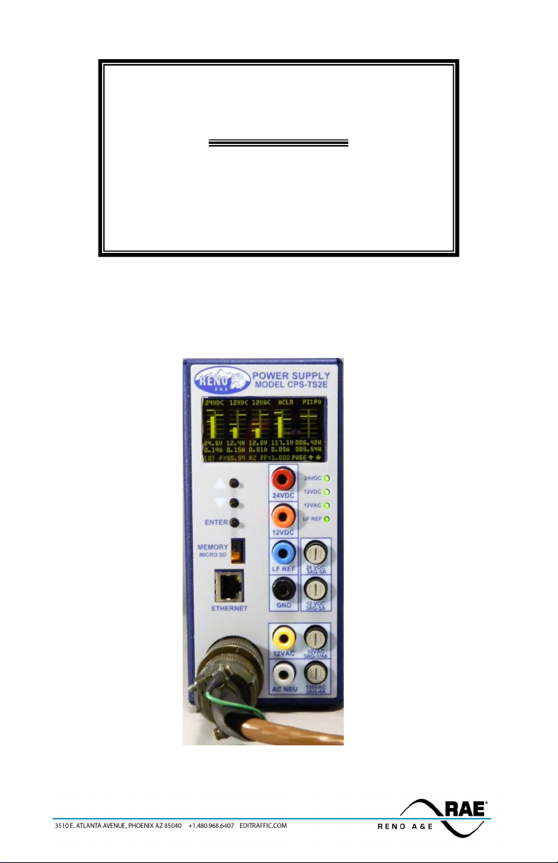
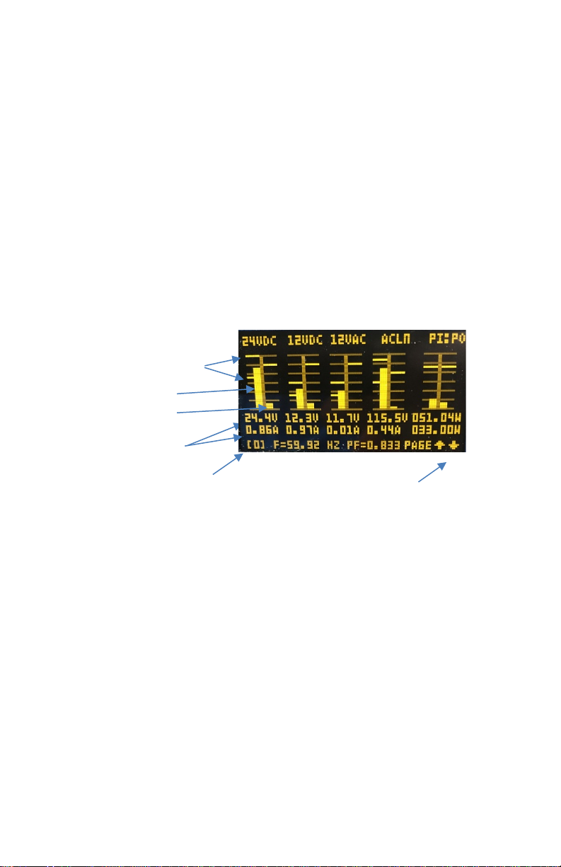
Locally at the CPS-TS2E PS, a very simple user interface is provided
enabling easy reading and tracking of all the measured values (for example

889-1429-00 CPS-TS2E Operation Manual Rev Apr 2021 Page 2
24VDC DC output voltage and current draw) with a single glance. The user
interface consist of a large OLED display and three momentary push-buttons
for firmware navigation and data entry. As mentioned all measured data is
saved onto a flash micro-SD card. Additionally, there are four processor
independent (hardware integral) LEDs providing the continuous status of the
DC and AC output voltages and AC Line input even if there is a processor
failure.
Even if the processor fails and cannot be reset, the power supply
will continue to function without interruption of safe regulated voltages
to the traffic cabinet.
On the front panel of the CPS-TS2E, the traffic technician has six
colored test jacks providing direct measurements with a multimeter of all AC
and DC outputs.
Section 2 Specifications
A. Physical
1. Size: 3.4 inches wide x 7.1 inches high x 7.4 inches deep
2. Weight: 2.71 pounds
3. Front Panel Connector: MS3106A-18-1SW
4. Mounting: Shelf
5. Circuit Boards: The printed circuit board is 0.062 inch thick FR4 material with
2 Oz. Copper. All holes are plated through. Circuit boards and components
are conformal coated with a polyurethane coating.
6. Enclosure: The enclosure is fabricated with powder coated alumi-num.
Attachment points are located on top and bottom for rigid mounting.
B. Environmental
1. Compliance: NEMA TS-2 2003 Standards
2. EMI Compliance: Radiated and conductive emissions are in compliance
with FCC part 15, Class A
3. Operating Ambient Temperature: -40º C to +85º C
C. Electrical Rating of Power Supply
1. AC Line Input Voltage: 80 VAC to 150 VAC
2. AC Line Input Frequency: 43 Hz to 65 Hz
3. AC Line Regulation: ±0.1%
4. Power Factor: ≥0.95
5. Efficiency: ≥80%
6. DC Outputs: 12 VDC ±2% @ 5 Amps and 24 VDC ±2% @ 5 Amps
7. Output Ripple: Less than 50 mV Peak to Peak

889-1429-00 CPS-TS2E Operation Manual Rev Apr 2021 Page 3
8. AC Output: unregulated 12 VAC, 60 HZ sine wave output referenced to AC
Line Neutral and supplies up to 250mARMS.
9. 12VAC Unregulated Output v.s. Load
10. Line Frequency Reference Output: The line frequency reference output is a
60 Hz square wave with amplitude of 24 VDC ±2% referenced to DC common.
The output can source or sink 100 mA. Transitions of the square wave occur
within ±50 microseconds of the AC zero crossing.
11. Soft Start: when starting up under heavy loads, power draw from the AC line
is ramped up over a 4 millisecond period.
12. In-Rush Current: In-rush current is limited to less than 3 Amps AC.
13. Self-Checking: Self-monitoring hardware shuts down the DC output in the
event of a failure or excessive load or over temperature.
14. Transient Voltage Protections
a. AC Input:
b. DC Outputs: 1500Watt, 30.8VDC transient voltage suppressor
c. AC Output: 1500 Watt, 33VAC transient voltage suppressor
d. Line Frequency Ref.: 3 Watt, 30 Volt Zener
15. Current Fold back on DC outputs: If current begins to exceed approximately
5.5 Amps on either the 12VDC or 24VDC outputs, the DC output will begin to
reduce the output voltage to maintain a fairly constant current output.
16. Non-Fused Over Current Protection: If the DC load exceeds 10 Amps for
longer than 100 milliseconds the DC output is shutdown. Once the excessive
load is removed the power supply recovers
17. Fuse Protection
a. AC Input: The AC Line input is protected with a 4 Amp slow blow 3AG
fuse (front panel accessible).
b. DC Outputs:The output is protected with 5 Amp 3AG Fast blow fuses
(front panel accessible).
c. AC Output: The output is protected with a 0.25 Amp 3AG front panel
slow blow fuse (front panel accessible).
d. Line Frequency Reference: The output is protected with a self-resetting
200 mA poly fuse.

889-1429-00 CPS-TS2E Operation Manual Rev Apr 2021 Page 4
D. Front Panel Indications
1. Not under processor control
a. DC Outputs: A red/green LED for the 12VDC and 24VDC outputs. The
LED will turn from green (in spec) to red (out of spec) color if either
measured voltage moves outside of +/- 1 VDC from the channels ideal
voltages of 12VDC and 24VDC. If either voltage disappears, its respective
LED goes dark.
b. AC Output: A green LED is illuminated with an intensity proportional to
the 12VAC voltage. As the voltage drops (such as with increasing load)
its intensity drops proportionally. If it goes away due for example a
blown fuse or loss of AC Line, it will go dark.
c. Line Frequency Reference: This green LED will flicker to indicate a
changing voltage. If 24 VDC output or AC Line Input or no square wave
is generated, the LED will go out.
2. Under Processor control
a. Front panel OLED Display: An organic light emitting diode display
providing outstanding readability from -30° C to +80° C. Allows viewing
and setup of all parameters and logs.
E. Front Panel Controls
1. Three momentary push buttons
a. Arrow Up: This button is typically used to increase a selected value or
during navigating the user screens to move the cursor up a tree view to
the next branch or to go to the next screen or when inside a text box
move the cursor to the right.
b. Arrow Down: This button is typically used to decrease a selected value
or during navigating the user screens to move the cursor down a tree
view to the next branch or to go to the next screen or when inside a text
box move the cursor to the left.
c. Enter: This button is typically used to select a value or a tree branch or
page during navigating the user interface.
F. Real-time Measurements
1. AC Line voltage: Root mean Square (RMS) voltage displayed is composed of
at least 512 measurements (samples) across each line cycle of AC line voltage
waveform.
2. AC Line voltage: Root mean Square (RMS) voltage displayed is composed of
at least 512 measurements (samples) across each line cycle of AC line voltage
waveform.
3. Power factor: determined from the ratio of real power to apparent power.

889-1429-00 CPS-TS2E Operation Manual Rev Apr 2021 Page 5
4. All DC and AC outputs and the AC input are continuously sampled once per
second by default; both the individual samples and a running average of the
measurements are recorded with the running average voltages and currents
being displayed. Input and output powers are continuously calculated based
on the running averages and displayed.
5. AC Line SAGs and Swells as defined by default or user definitions are counted
and recorded.
G. Events Logged (Time and Date Stamped records)
1. Low or High AC Line input Voltage, current, and frequency including SAGs,
Swells, and power bumping. Setpoints for alerts are user settable.
2. Low or High DC output Voltages and currents. Setpoints for alerts are user
settable.
H. Storage Capacity: A 2 GB µSD standard density card comes with the power supply.
µSD card port can handle up to the 4 GB of the standard density cards.
I. Networking Services
1. TCP Nano-server host built-in interactive webpage
2. UDP server with built in SNMP Agent
3. Remote procedure calls in both TCP and UDP server modes
Section 3 Navigating the User Interface
A. General
The user interface is straight forward and easy to navigate; it consist of
a set of main pages (or screens) each giving either status or configuration
parameters for the power supply.
In essence, there are two types of pages: Information and Configuration.
Info pages display either real-time measure of voltages and currents (for
example, bar graphs of DC and AC voltages and currents) or health metrics
of the actual power supply hardware and firmware (for example, uSD card
access time or number of writes since last reset). In addition, Info pages
provide status on alarms (on or off) and transmitted and received
messages.
On the other hand, Config pages allow adjustments on run-time
parameters as for example alarm setpoints or logging start and stop times.
Networking parameters like IP address or type of nano-server (UDP or
TCP) are fully configurable.

889-1429-00 CPS-TS2E Operation Manual Rev Apr 2021 Page 6
The different pages are listed in section B in increasing page number
with a detailed explanation for how to navigate and utilize each page.
1. How to scroll through the main pages. With the front panel Up and
Down pushbuttons (PBs), the pages are sequentially displayed as if
scrolling forwards or backwards through a list. The “ENTER”
pushbutton (PB) is pressed to select and enter into a specific main
page. Like a book, each page is numbered; and helpful on-screen
messages appear for navigating into and out of a main page.
2. How to scroll through a selected page Tree structure.With the
exception of the default page (page 0) and the general status page
(page 1), all other pages use a tree structured menu.
a. Once entering into a main page, the UP and Down PBs moves to any
main branch of the tree; that branch becomes highlighted. As each
main branch becomes highlighted, it opens up revealing any of its
sub-branches.
b. To exit a particular page navigate to the “ESC” main branch and then
press the Enter PB. Now, the UP and Down PBs will take you to a
different main page.
c. To explore a main branch sub-branches, simply push the Enter PB
for the highlighted main branch. The first sub-branch will brighten
and its value also appears (that is, the leaf of the sub-branch
appears). A leaf is the very end of a tree sub-branch and in which
resides the associated parameter; the parameter may or may not be
editable; some parameters are changeable like configuration
parameters and others are not as for example a measured voltage.
Use the Up and Down PBs to move to the different sub branches;
they will expand and collapse accordingly.
d. To return to the previous level of a tree (from Sub branch to Main
branch) navigate to the sub branch labeled “ESC” and press the
Enter PB.
3. How to edit a parameter. If a parameter in a leaf is changeable, while
that leaf is highlighted, pressing the Enter PB initiates the editing of
the parameter’s value; the first character of that parameter value
becomes highlighted. Pressing either the UP or Down PBs moves to the
next character either to the right or to the left; here, the Up PB moves
to the right and the Down PB moves to the left. To change a highlighted
character to a different value, momentarily press the Enter PB and
then use the UP and Down PBs to scroll through a list of

889-1429-00 CPS-TS2E Operation Manual Rev Apr 2021 Page 7
possible values. Once the desired value for the character is found (like
any number from 0 through 9 or any letter A through Z), press the
Enter PB again to select and lock in the new character at this position
of the parameter’s value. The UP and Down PBs are now once again
free to move to a different position where editing can then be repeated
if required. When the parameter’s value adjustment is complete, the
new value is updated and saved by moving to the asterisk (“*”) at the
end of the value and then press the Enter PB. This will take you out of
editing mode. Continue navigation of the sub-branches can resume
using the Up and Down PBs.
B. Available Pages (screens)
1. Overview Page (Default Page, Page 0)
Figure 2 – Overhead Display
When the power supply is powered on or after a processor reset,
this page appears as the default page. With a simple glance, the page
offers an overview of the DC and AC outputs and AC Line input
measured values.
If there is no activity with the front controls for 5 minutes, the
power supply will automatically return to this page from any other
main page. After 15 minutes of no activity with the front panel
controls, the display will go blank only to return if any front panel
button is pressed.
This page displays labeled bar graphs depicting the real-time
measure of the DC and AC voltages and currents, figure 2. Also, a bar
graph of the real input power and output power is calculated based
on these measurements. Each parameter is composed of two bar
graphs setting side by side with its name at the top. The bar graph to
Page Number
High and Low Voltage
Alarm Setpoints
UP and Down Button Status
Real time measured
voltage and current
Voltage Bar graph
Current Bar graph

889-1429-00 CPS-TS2E Operation Manual Rev Apr 2021 Page 8
the left is voltage and the bar graph to the right is the current. In the
case of the power bar graph, the bar graph to the left is real AC Input
power and the bar graph to the left is the total output power
delivered by the power supply to the cabinet.
At the very bottom of the page, the measured frequency and
power factor are also shown. If an alert occurs such as, for example, a
low AC line voltage, the frequency and power factor indication is
replaced with a blinking message of this alert. The frequency and
power factor returns when all alerts are cleared.
Towards the lower right hand corner of this page, is the word
“page” adjacent to an up and down arrow. This message indicates that
if the Up or Down PBs is momentarily pushed prior to pushing the
“Enter” button, the display navigates to a new main page. If the
“Enter” button is pushed first prior to the Up or Down PBs, the
Overview page is selected and entered into.
When this page is selected, the top 24VDC Label will begin to blink
and the “page” message next to the up and down arrows will
disappear replaced with the message “CHAN.” and the up and down
arrows begin to blink. If either the up or down buttons are now
pressed, the adjacent label for example 12VDC will begin to blink and
the previous label (in this case the 24VDC) will regain normal
intensity and stop blinking. When any of these top labels are blinking
and the “Enter” button is pushed, the overview page is replaced with
a strip chart (graph voltage and current amplitude verses time) for
the parameter specified by the previously blinking label.
Figure 3 – Strip Chart Display, AC Line Voltage and Current as example.
The strip chart graphs the 60 seconds of the selected parameter
voltage and current. The graph refreshes when it reaches 60 seconds.
Pressing “Enter” again returns to the overview page and the Up
and Down PBs are then again free to navigate to a new main page if
now pressed.

889-1429-00 CPS-TS2E Operation Manual Rev Apr 2021 Page 9
2. General Status Page, Page 1
From the previous page, if the Up button is pressed before the
Enter button, the general status page appears next. It is page 1.
This page depicts general information about the PS, see figure 4.
For example, the page conveniently provides not only the IP
Address assigned to the PS, but also the type of internet server
currently selected (TCP/IP versus UDP). Additionally, the number
of cleared alarms (alerts), SAG and SWELL events, firmware
version and serial number are provided.
Figure 4 – General Status Page
If there are any on-going alarm conditions (e.g., 24VDC output high
current), those alarms would list here instead of the general status
information with a time and date stamp of when the alarm(s) had
occurred. When all alarms clear, the general status information reappears.
On this page, the parameters displayed are not editable by the user.
Pressing the Enter button while this page is displayed has no effect.
Pressing the Down PB moves back to the Overview page, page 0.
And pressing the UP PB, moves to the next page, Device detail page, page
2.

889-1429-00 CPS-TS2E Operation Manual Rev Apr 2021 Page 10
3. Device Details Page, Page 2
Specific run-time status and metrics of the power supply hardware are
displayed on this page, figure 5. SD is the scan disk; and RT Clock is the
real time clock for example. Being measured, these parameters are not
editable.
Figure 5 – Device Detail Page
By momentarily pressing the Enter PB, entry is gained into this page. The
first item listed, the uSD Flash drive, expands into four branches, figure 6.
The up and down arrow on a branch indicates the assigned function of the
UP and Down PBs.
Figure 6 – Device Detail Page after Enter PB is pressed
To navigate to the other branches momentarily depress the Up or Down
PBs as desired. Subsequent branches will expand showing their sub-
branches, while the previously opened branch will collapse. Refer to
figure 7.
Figure 7 –Device Detail Page: Navigating the main branches

889-1429-00 CPS-TS2E Operation Manual Rev Apr 2021 Page 11
To navigate any leaf (or sub-branch), momentarily depress the Enter PB.
Now the Up and Down PBs will allow you to navigate these leaves. When
selected, the leaves display their current value. These values are
measured parameters and are not editable by the user.
Figure 8 – Device Detail Page: Navigating the leaves and their values
To return to the previous level of the tree, using the UP and Down PBs,
navigate to the leaf labeled “ESC” and then momentarily press the Enter
PB, figure 9.
Figure 9 – Device Detail Page: Navigating back to Main Branch
In order to escape the Detail Page and subsequently navigate to the next page,
use the UP or Down PB to move to the main branch labeled “ESC”. Then
momentarily depress the Enter PB. The “ESC” label becomes un-highlighted
and the message text in lower right corner of the display will change from
“Navigate” to “Exit Page”. Now pressing either the Up or Down PBs, the next or
previous page is displayed respectively. Refer to figure 10.
Figure 10 – Device Detail Page: Exiting and ready to go to next page

889-1429-00 CPS-TS2E Operation Manual Rev Apr 2021 Page 12
4. Alert (or Alarm) Setpoints Page, Page 3.
By pressing the UP PB from the previous page (Detail Page), Alert Levels
configuration page appears. See Figure 11. Like the previous page, the page is
organized as a tree with branches and leaves. Each branch contains the high
and low voltage setpoints and the high current setpoint for each DC and AC
outputs as well as the AC line input. Each leaf will contain the user editable
value of that setpoint.
Figure 11 – Alert Setpoint Page
Entering and subsequent navigating through this tree is accomplished in the
same way as described previously with the Device Detail Page, figure 12.
Figure 12 – Exploring the main branches
And as demonstrated previously in the Device Detail Page, selecting a sub-
branch to explore is accomplished by pressing the Enter PB and then using the
Up and Down PBs to further navigate the selected sub branch as the up and
down arrows now indicate, figure 13.
Figure 13 – Navigating the sub branches

889-1429-00 CPS-TS2E Operation Manual Rev Apr 2021 Page 13
To edit a particular leaf value of a sub branch, navigate to the desired branch
(highlighted), then momentarily depress the Enter PB. The first character of
the value is highlighted. See figure 14.
Figure 14 – Editing a Setpoint
The Up or Down PBs will move to any position in the leaf’s value. The Enter PB
selects that position for change. When a character in a particular position is
selected for change by momentarily pressing the Enter PB, pressing either the
UP or Down PBs will now scroll through the allowable values for that
character in that position. Once the desired value is found, select the choice by
again pressing the Enter PB. This changes the character and moves the cursor
to the next available character. The Up and Down PBs will then return to their
previous function of moving to different positions in the value.
To exit the value edit mode and save the new value, use the UP and Down PBs
to move to the asterisk (“*”) and then press the Enter PB. The UP and Down
PBs are now free to explore the other sub-branches and their respective leaves
can be navigated to as previously describe, Figure 15.
Figure 15 – Asterisk highlighted; ready to update and store new value
and exiting edit mode.
5. Parameters Page, page 4.
Page 4 provides the means to change how the power supply logs
measured data; see figure 16.
Figure 16 – Parameter Page prior to entry
Enter PB

889-1429-00 CPS-TS2E Operation Manual Rev Apr 2021 Page 14
Upon entering this page, figure 17, the user is able to adjust how the
power supply logs/records measured data to the uSD card, define the
SAG-Swell magnitudes’, and set the real time clock. The parameter main
branch provides the ability to re-instate factory default parameter values,
save any newly entered parameters into flash memory becoming the new
default values.
Navigating and editing parameters is accomplished in the same manner
as described and depicted earlier.
Figure 17 – Parameter Page after entry
6. Networking Page, page 5.
The Networking page, page 5, offers the means for configuring the LAN
connectivity of a power supply. For example, common networking
parameters such as IP address, IP mask, and Gateway are accessible for
alteration, figure 18.
Figure 18 – Networking Page before and after entry
Additionally, the TCP/IP or UDP server hosted by a power supply is
selectable and Ethernet ports are defined, figure 19.
Figure 19 – Navigating to the TCP or UDP Server branch.

889-1429-00 CPS-TS2E Operation Manual Rev Apr 2021 Page 15
Finally, under the security branch, password protection is enable or
disabled along with the ability to change the current password, figure 20.
If enabled, the password must be entered before any parameters can
undergo editing. Moreover, the password only opens up a 15 minute
window in which editable parameter values can undergo editing. After
the 15 minutes, the password (if enabled) must be re-supplied.
Figure 20 – Navigating to the TCP Server branch.
7. Physical Location Page, page 6
The Location page is the final main page; it allows the entry of a power
supply’s physical location by cross streets (x-cross), GPS coordinates,
and/or an identification code, figure 21.
Figure 21 – Navigating the Location page.

889-1429-00 CPS-TS2E Operation Manual Rev Apr 2021 Page 16
Section 4 TCP Nano-Server Default webpage
The default web page hosted by the power supply is fully written in html and
strictly adheres to a stark and simple design. Thus, the greatest diversity of internet
browser can use the web page to remotely configure and obtain measured data
from a power supply. Yet this does not prevent a user from designing a custom
external web page taking full advantage of the remote procedure calls to obtain and
configure a particular power supply.
On a LAN or directly connected to a power supply’s Ethernet port, a PC can connect
to a power supply by simply running the PC’s internet browser and typing into the
address bar the power supply’s assigned IP address. The default web page will
come up and display the real-time information, see figure 22.
Figure 22 – Default Web Page.

889-1429-00 CPS-TS2E Operation Manual Rev Apr 2021 Page 17
The operational parameters are by default hidden; yet appear by submitting a
“Y” or “Yes” to the question at the bottom of the web page, figure 23.
Figure 23 – Default Web Page, a few configuration parameters.
All the web page controls used are simple and intuitive to use for adjusting the
operational parameters.
Table of contents