4
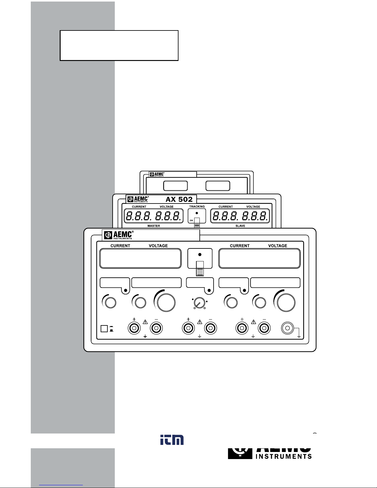
DC Power Supply Models AX501, AX502 and AX503
1.2 Definition of Measurement Categories
CAT I: FormeasurementsoncircuitsnotdirectlyconnectedtotheAC
supply wall outlet such as protected secondaries, signal level,
andlimitedenergycircuits.
CAT II: For measurements performed on circuits directly connected to
the electrical distribution system. Examples are measurements
onhouseholdappliancesorportabletools.
CAT III: For measurements performed in the building installation at
the distribution level such as on hardwired equipment in xed
installationandcircuitbreakers.
CAT IV: For measurements performed at the primary electrical supply
(<1000V) such as on primary overcurrent protection devices,
ripplecontrolunits,ormeters.
1.3 Receiving Your Shipment
Uponreceivingyourshipment,makesurethatthecontentsareconsistent
withthepackinglist.Notifyyourdistributorofanymissingitems.Iftheequip-
mentappearstobedamaged,leaclaimimmediatelywiththecarrierand
notifyyourdistributoratonce,givingadetaileddescriptionofanydamage.
Savethedamagedpackingcontainertosubstantiateyourclaim.
1.4 Ordering Information
DCPowerSupplyModelAX501.......................................... Cat. #2130.05
(Single output, 0 to 2.5A; 0 to 30VDC)
DCPowerSupplyModelAX502.......................................... Cat. #2130.06
(Dual output, 0 to 2.5A; 0 to 30VDC)
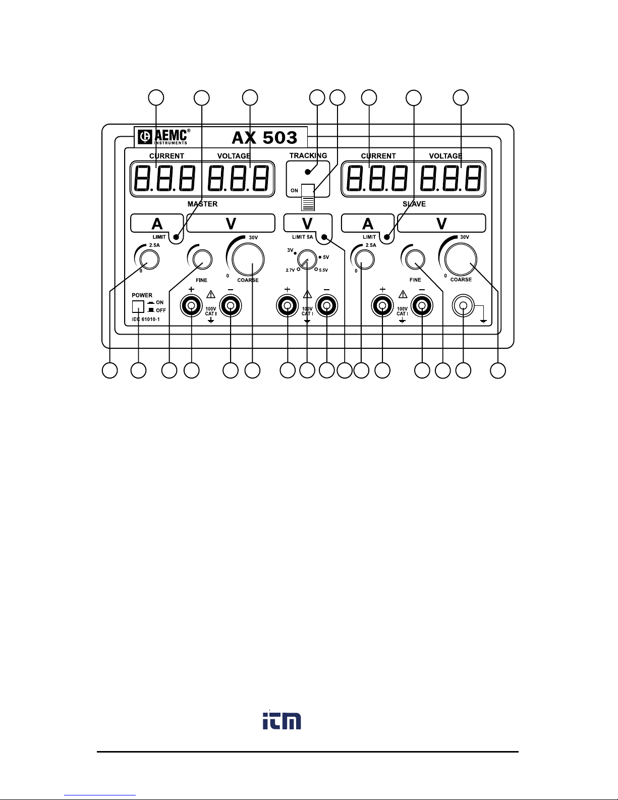
DCPowerSupplyModelAX503.......................................... Cat. #2130.07
(Triple output, two 0 to 2.5A; 0 to 30VDC; 5A; 2.7 to 5.5VDC)
All models
are shipped with a product warranty and registration card and user manual.
1.4.1 Accessories
LeadSet(2color-codedleads,1groundlead,
2alligatorclipsand2gripprobes)....................................... Cat. #2117.78
Setof5Fuses10A/250V,5x20mmSlowBlow ................... Cat. #2118.83
Order Accessories and Replacement Parts Directly Online
Check our Storefront at www.aemc.com/store for availability