CPS C3T User manual

CPS C3T 15kV
A
three
p
hase out
p
ut
User Manua
l

Pag. 52/53 MT-HC3TK15E1599NP-US 00

MT-HC3TKE301406NP-US 00 pag 3/53
INDEX
1.STORAGE........................................................................................................8
2.INSTALLATION ROOM.................................................................................8
3.PRELIMINARY OPERATIONS.....................................................................8
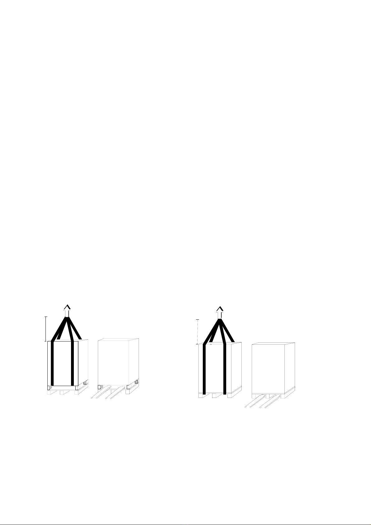
3.1Checking the packaging ................................................................................................. 8
3.2Positioning .....................................................................................................................9
4.SETTING UP THE ELECTRICAL SYSTEM................................................9
4.1Protection to be installed:..............................................................................................9
4.1.1Residual Current Detector (RDC)................................................................................................... 10
4.2Mains, load and battery connections ...........................................................................10
4.2.1Configuration with single mains supply.......................................................................................... 11
4.2.2Configuration with split bypass input.............................................................................................. 11
4.3Backfeed protection......................................................................................................12
4.3.1Emergency power off device (EPO) ................................................................................................ 12
4.4Mains, load and battery connections ...........................................................................13
4.5External Battery connections.......................................................................................14
4.6Connection of signals and remote commands..............................................................16
4.6.1EPO connector (emergency power off control)............................................................................... 16
4.6.2REMOTE COMMANDS AND ALARMS ......................................................................................... 16
4.6.3RS232............................................................................................................................................... 17
4.6.4Parallel (optional)........................................................................................................................... 18
4.6.5SLOTS 1-2 , the following cards may be inserted (optional):......................................................... 18
4.6.6REMOTE ALARMS (optional card) ................................................................................................ 19
4.6.7MULTI I / O (optional)................................................................................................................ 19
4.6.8REMOTE PANEL (OPTIONAL)...................................................................................................... 19
4.6.9Dual Bus System – UGS (optional) ................................................................................................. 19
4.6.10SWOUT and SWMB aux - External temperature sensor(optional)................................................. 20
4.7Start-up procedure .......................................................................................................23
4.7.1Battery operation check................................................................................................................... 24
4.8Operating modes ..........................................................................................................25
4.8.1On - line - factory setting - ............................................................................................................. 25
4.8.2Standby-on / Smart active................................................................................................................ 25
4.8.3Standby-off (with mains present the load is not powered).............................................................. 26
4.8.4Stabilizer (operation in on-line mode without battery) .................................................................. 26
4.8.5Frequency converter (from 50 to 60Hz or vice versa)..................................................................... 26
4.9Personalizations...........................................................................................................27
4.10Procedure to transfer the load from CPS onto maintenance by-pass..........................27
4.11CPS and load shutdown ............................................................................................... 28
4.12Block diagram ..............................................................................................................29
4.13Components of the block diagrams..............................................................................30
5.CPS IN PARALLEL CONFIGURATION.................................................................33
5.1Introduction..................................................................................................................33
5.2Electrical system set-up................................................................................................34
5.2.1Input................................................................................................................................................. 34
5.2.2Differential ...................................................................................................................................... 34
5.2.3Emergency power off device (EPO) ................................................................................................ 34

Pag. 52/53 MT-HC3TK15E1599NP-US 00
5.2.4External maintenance by-pass......................................................................................................... 35
5.3Mains, load and battery connections ...........................................................................36
5.3.1CPS AC input / output power connection........................................................................................ 36
5.3.2Power connections battery side....................................................................................................... 37
5.4Connection of signals...................................................................................................39
5.5Start-up procedure .......................................................................................................42
5.6Operating modes ..........................................................................................................43
5.7By-pass for maintenance..............................................................................................45
6.MAINTENANCE.................................................................................................49
7.SPECIFICATIONS .......................................................................................50
8.APPENDIX A-REMOTE COMMANDS AND ALARMS CARD -................................52
Thank you for choosing our product.
Symbols used in the manual
In this manual, some operations are shown by graphic symbols to alert the reader to the dangerous nature of the
operations:
Possibility of serious injury or substantial damage to the device, unless adequate
precautionary countermeasures are taken.
This symbol indicates some important information which must be read with care.
It is recommended to read this part of the manual.
N.B. In the picture or table the word CPS means CPS.

MT-HC3TKE301406NP-US 00 pag 5/53
Protective equipment to be worn
No maintenance operations must be carried out on the device without wearing the Personal Protective Equipment (PPE)
described below.
Personnel involved in the installation or maintenance of the equipment must not wear clothes with wide sleeves or
laces, belts, bracelets or other items that may be dangerous, especially if they are metallic. Long hair must be tied in
such a way as to ensure that it is not a hazard.
The following signs show the protective equipment that should be worn. The various items of PPE must be selected and
sized according to the nature of the hazard (particularly electrical) posed by the equipment.
Accident prevention footwear
Use: always
Protective eyewear
Use: always
Protective clothing
Use: always
Helmet
Use: When there are suspended loads
Work gloves
Use: always

Pag. 52/53 MT-HC3TK15E1599NP-US 00
Definition of “operator” and “specialized technician”
The professional figure responsible for accessing the equipment for ordinary maintenance purposes is defined with the
term operator.
This definition covers personnel that know the operating and maintenance procedures for the equipment, and that have
been:
1. trained to operate in accordance with the safety standards relating to the dangers that may arise where
electrical voltage is present;
2. trained to use Personal Protective Equipment and to carry out basic first aid.
The professional figure responsible for the installation and start-up of the equipment, and for any extraordinary
maintenance, is defined with the term specialized technician.
This definition covers personnel that, in addition to the requirements listed above for a general operator, must also:
1. have been suitably trained by the manufacturers or their representative.
2. be aware of installation, assembly, repair and service procedures, and have a specific technical qualification.
3. must have a background of technical training, or specific training relating to the procedures for the safe use
and maintenance of the equipment.
Emergency interventions
The following information is of a general nature.
First aid interventions
Company regulations and traditional procedures should be followed for any first aid intervention that may be required.
Firefighting measures
1. Do not use water to put out a fire, but only fire extinguishers that are suitable for use with
electrical and electronic equipment.
2. If exposed to heat or fire, some products may release toxic fumes into the atmosphere.
Always use a respirator when extinguishing a fire.

MT-HC3TKE301406NP-US 00 pag 7/53
GENERAL PRECAUTIONS
This manual contains detailed instructions for the use, installation and start-up of the CPS . Read the
manual carefully before installation. For information on using the CPS , the manual should be kept close
at hand and consulted before carrying out any operation on the device.
This device has been designed and manufactured in accordance with the standards for the product, for normal use
and for all uses that may reasonably be expected. It may under no circumstances be used for any purposes other
than those envisaged, or in any other ways than those described in this manual. Any interventions should be carried
out in accordance with the criteria and the time-frames described in this manual.
PRECAUTIONS AND SAFETY REGULATIONS
Refer to the “Safety and Compliance Manual” supplied with the CPS (0MNA141_NE).
ENVIRONMENTAL PROTECTION
In the development of its products, the company devotes abundant resources to analysing the
environmental aspects.
All our products pursue the objectives defined in the environmental management system developed by
the company in compliance with applicable standards.
No hazardous materials such as CFCs, HCFCs or asbestos are used in this product.
When evaluating packaging, the choice of material has been made favouring recyclable materials.
For correct disposal, please separate and identify the type of material of which the packaging is made in the table
below. Dispose of all material in compliance with applicable standards in the country in which the product is used.
DESCRIPTION MATERIAL
Box Cardboard
Protective bag Polythene
Accessories bag Polythene
DISPOSING OF THE PRODUCT
The CPS contain electronic cards and batteries which are considered TOXIC and HAZARDOUS waste. When the
product reaches the end of its operating life, dispose of it in accordance with applicable local legislation.
Disposing of the product correctly contributes to respecting the environment and personal health.

Pag. 52/53 MT-HC3TK15E1599NP-US 00
1. STORAGE
If the CPS is not to be installed immediately it must be stored within the original packaging and protected from
moisture and weather. The area used to store the equipment must have the following characteristics:
Temperature: -25°÷ + 60°C (-13°÷140°F)
Relative humidity: 90% max
The recommended storage temperature is between +10° to 30°C (+50° e 86°F).
2. INSTALLATION ROOM
The CPS and its battery cabinet are designed for indoor installation. The following points should be observed when
choosing the place of installation:
avoid dusty environments;
ensure that the floor is level and able to support the weight of the CPS and the battery cabinet;
avoid sites that are too narrow as this may impede normal maintenance operations;
the ambient relative humidity must not exceed 95%, non-condensing;
avoid positioning in sites exposed to direct sunlight or hot air;
ensure that the ambient temperature, with the CPS operating, remains between :
operating temperature: 0 ÷ + 40 °C
maximum temperature for 8 hours a day: + 40°C
mean temperature for 24 hours: + 35°C
Note: - The recommended operating temperature for the CPS and for the batteries life is between 20 and 25°C.
To keep the temperature of the installation room within the range indicated above, a system has to be provided to
remove the dissipated heat (for the value of the kcal/kW dissipated by the CPS refer to the “SPECIFICATIONS”).
3. PRELIMINARY OPERATIONS
3.1 Checking the packaging
When you receive the CPS check that the packaging has not been damaged during transportation. Confirm that neither
of the two anti-shock/tilt devices fixed to the packaging have been activated. If this has happened follow the
instructions provided on the packaging. Be careful when removing the packaging materials so as not to scratch the
CPS cabinet.
The equipment must be handled with care as it could be damaged if it is dropped or banged.
The CPS is supplied with:
user instruction manual
CD-ROM with the CPS management software & communications cable
RIMOZIONE DEL PALLET / TO REMOVE THE PALLET
1000
MOVIM ENTAZIONE CON IMBALLO / HANDLING WITH PACKING
1000

MT-HC3TKE301406NP-US 00 pag 9/53
3.2 Positioning
The air enters the CPS through ventilation grills located in the front door and exit through the fan grills located on the
rear panel. The following should be taken into account when choosing a position for the CPS:
a space of at least one meter must be kept clear in front of the equipment for start-up/shutdown operations and any
maintenance operations that may be required
leave a minimum distance of 60cm between the top of the CPS and the ceiling of the room, to enable adequate
circulation of the air exiting from the system
leave a minimum distance of 30cm between the rear of the CPS and the relative wall of the room, to enable
adequate circulation of the air exiting the system
The AC-DC INPUT/OUTPUT cables enter from the bottom of the CPS. Access to the power and auxiliary
terminals and the switchgear is from the front.
For the mechanical dimension of the CPS refer to the installation diagram supplied with the USER MANUAL
The installation diagram identifies:
- the position of the holes in the base plate through which the equipment can be bolted to the floor;
- the base view to design a pedestal (if the CPS is to be located on a raised floor);
- cable entry position;
- position of the fans on the rear of the CPS.
4. SETTING UP THE ELECTRICAL SYSTEM
4.1 Protection to be installed:
- Connection table -
15
INPUT (F)
Imax (*) [A] 33
Fuse gG type [A] 50
BYPASS (G) (*)
Current [A] 26
Fuse gG type [A] 32
OUTPUT
Rated current [A] 22
BATTERY
Battery eq. permanent current [A] 38
(*) 120% load, nominal input voltage and battery recharging. External protection can be inserted at the CPS input..
Ac input
On the incoming mains supply of the the CPS, in the distribution cabinet, must be install a overcurrent protections.
This protection shall be made with fuse type as shows in the table or with equivalent circuit breaker.
For dual incoming supplies, separate protective devices must be installed for the Rectifier and the Bypass inputs.
Battery
ATTENTION
Any battery cabinet must have its own fuses on its output terminals “+” and “-“.
Remember that those fuses must be able to open the dc voltage.
If using the “Rapid” fuse, type gG/gL NH,
the MAXIMUM size of the battery fuse must be below 2 times the nominal battery capacity.
If using the “Ultra Rapid” fuse, type aR NH,
the MAXIMUM size of the battery fuse must be below 2.5 times the nominal battery capacity.
For example: battery type 150Ah we can use 250A gG/Gl or 315A aR.

Pag. 52/53 MT-HC3TK15E1599NP-US 00
4.1.1 Residual Current Detector (RDC)
A differential switch (RCD) must be inserted into the mains supply input (CPStream).
The differential switch located CPStream must have the following characteristics:
- Sensitivity 500mA;
- sensitive to d.c and unidirectional pulses (class B)
- insensitive to transient current pulses
- class A or class B
- delay greater or equal to 0,1s
In the standard version, where there is no isolation transformer in the by-pass line, the neutral input from the mains
supply is directly connected to the output from the CPS.
INPUT NEUTRAL CONNECTED TO OUTPUT NEUTRAL
THE ELECTRICAL SYSTEMS LOCATED CPSTREAM AND DOWNSTREAM OF THE CPS ARE IDENTICAL
When operating in the presence of mains supply, a differential breaker (RCD) installed on the input will intervene as
the output circuit is not isolated from the input circuit.
When operating without mains supply (from battery) the input differential breaker will intervene only if it is able to
switch as a result of leakage current without any voltage at its poles (for example a differential breaker with an
auxiliary relay is not suitable). However it is possible to install additional differential breakers on the output of the CPS,
possibly coordinated with those on the input.
4.2 Mains, load and battery connections
THE FOLLOWING OPERATIONS DESCRIBED IN THIS CHAPTER MUST BE PERFORMED BY
TRAINED PERSONNEL.
THE FIRST CONNECTION TO BE MADE IS THE GROUND/EARTH CONNECTION TO THE TERMINAL
MARKED 'PE'. THE CPS CANNOT OPERATE WITHOUT CONNECTION TO THE GROUND/EARTH SYSTEM.
Before connecting, ensure that that the CPS equipment is totally isolated from any external power sources, battery and
mains line, and that all of the CPS switches are open, in particular:
- the CPS mains supply input is completely isolated
- all of the switches on the CPS: SWIN, SWBY, SWOUT, SWMB, are in the OFF position
- the output switch of the battery cabinet is in the open position
- always ensure that no hazardous voltages are present by measuring with a multi-meter.
For the power cable connection to the CPS terminal board refer to installation diagram supplied with USER
MANUAL
.

MT-HC3TKE301406NP-US 00 pag 11/53
4.2.1 Configuration with single mains supply
NOTE: The feed must be three-phase
with neutral. The CPS cannot work
without input neutral (*).
F - For the installation of the protective
devices on the input, refer to the
“connection table”.
(*)The operation without input neutral
is admitted only with transformer
(delta-star) on the input line .
The links between the SWIN and SWBY switches are pre-fitted.
The cables must be terminated using pre-insulated crimp terminals and should be connected as shown in installation
diagram supplied.
4.2.2 Configuration with split bypass input
NOTE: The by-pass supply must be
three-phase with neutral. The CPS
cannot work without input neutral
on the by-pass line (*).
F - For the installation of the
protective devices on the input, refer
to the “connection table”.
(*) The operation without input
neutral is admitted only with
transformer (delta-star) on the input
bypass line .
- remove the links between mains
line and by-pass line
The cables must be terminated using
pre-insulated crimp terminals and
should be connected as shown in
installation diagram supplied.

Pag. 52/53 MT-HC3TK15E1599NP-US 00
4.3 Backfeed protection
The CPS is provided with a device to prevent voltage backfeed on the input line due to an internal fault. This
protection device works by switching off the inverter if the current flow is faulty, thereby causing voltage backfeed on
the by-pass line during operation from the inverter. If the fault occurs when the CPS is operating from the battery, the
load will not be powered.
Should it be required to avoid the shutting down of the inverter in order to keep the load powered by the inverter even
in the event of a double fault, the system can be customized to control the opening coil of a switch located CPStream by
reprogramming one of the relays on the “REMOTE COMMANDS AND ALARMS” card.
The control logic allows the function of the relay to be reconfigured, for example for the backfeed alarm, and then the
free voltage contact can be used to control the triggering of a switch located on the CPS input.
4.3.1 Emergency power off device (EPO)
The CPS is pre-set to be connected to a remote emergency power off device as laid down in standard EN 62040-1-2. If
the remote device (not supplied with the equipment) is activated, the inverter output voltage is cut.
The connection procedure is shown below.
a - EPO terminal board located on the CPS
b - EPO switch (not provided).
On the CPS , the jumper on the EPO terminals (page 16) must be removed, and the wires from the auxiliary contact of
the button must be connected in place of the jumper.
The contact must be closed with the button in the rest position and must open when the button is pressed.
UPS
a
b

MT-HC3TKE301406NP-US 00 pag 13/53
4.4 Mains, load and battery connections
The operations described in this chapter must be carried out exclusively by a specialized technician.
The first connection to be made is the earth conductor.
THE CPSMUST NOT OPERATE WITHOUT AN EARTH CONNECTION
Before making the connection, open all the switches on the device and ensure that the CPS is completely isolated from
the power sources: battery and AC power line. More specifically, check that:
- the CPS input line or lines are completely isolated;
- the battery cabinet disconnector / fuse (if present) is open;
- all the CPS disconnectors - SWIN, SWBY, SWOUT and SWMB - are in the open position;
- check with a multimeter that there are no dangerous voltages on the terminal board.
For connection of the power cables to the terminal boards, refer to the “INSTALLATION DRAWINGS”
provided with the CPS and with the battery cabinet, if present.
Input neutral
The power supply to the CPS input (by-pass line) must be three-phase with neutral.
The neutral conductor is necessary only on by-pass line.
Input line without neutral.
The transformer must be inserted either on the mains supply line or on the by-pass line (as shown in the drawings).
-transformer on the bypass line only
MAINS LINE
UPS
LOAD
3Ph+N
or
OPTIONAL
MAINS LINE
UPS
LOAD
3Ph+N
BY-PASS LINE
or
OPTIONAL

Pag. 52/53 MT-HC3TK15E1599NP-US 00
-The transformer supply bypass and mains lines
\ Input and output line without neutral
If the input line and the load are three-phase without neutral type (and only in this case), a kit to create
the signal neutral (optional) may be used. The kit may only be used by a specialized technician.
4.5 External Battery connections
BATTERY CABINET if present:
The battery cabinet must be provided with a fuses to be connected to the CPS.
Up to 3 battery cabinets can be connected in parallel,
in accordance with the diagram below.
MAINS LINE
UPS
LOAD
3Ph
OPTIONAL
UPS
-
Battery cabinet
+
Battery cabinet
SWBAT2
-
max 3 battery cabinet
+
SWBAT3
-
+

MT-HC3TKE301406NP-US 00 pag 15/53
CABINET DISCONNECTOR
For systems with 4 or more battery cabinets, use a Battery switch cabinet where the cables can be
parallel-connected (refer to the marketing department). For the sizing of the cables and connection
procedures, refer to the “INSTALLATION DRAWING” attached to the battery cabinet.
For back-up times requiring a greater number of Battery cabinets, contact the marketing department.
Battery switch cabinet
+
+
-
-
SW
Battery cabinet
UPS
-
+
Battery cabinet
SWBAT1
+
-
SWBAT4
-
+

Pag. 52/53 MT-HC3TK15E1599NP-US 00
4.6 Connection of signals and remote commands
To the position of the signal and remote connection, refer to the “INSTALLATION DRAWINGS” supplied with the
CPS.
4.6.1 EPO connector (emergency power off control)
If the jumper on the connector is opened, the voltage on the CPS output
will be cut.
The CPS is factory-fitted with the EPO terminals shortcircuited. If this
input is used, the CPS can be shut down in a hazardous situation from a
remote position simply by pressing a button.
If only the power supply is removed, for example by opening the switch
of the power supply panel, the CPS will keep the load powered using
the energy in the batteries.
4.6.2 REMOTE COMMANDS AND ALARMS
The card is equipped with a terminal board with 12 positions which has the following:
POWER SUPPLY 1 power supply 12Vdc 80mA(max.) [pins 10 and 11];
ALARMS 3 potential-free change-over contacts for alarms;
COMMAND 1 command programmable from the panel [pins 11 and 12];
The functions of the three contacts and the command may be reprogrammed via the display panel. The ALARMS and
the COMMAND are factory-set in the following way:
- ALARMS
- RL1 Bypass / fault, the contact changes position when the CPS switches the load onto the
by-pass line either during normal operation (e.g. due to overload) or as a result of a
fault in the inverter stage;
- RL2 Battery discharging, the contact changes position when the load is powered from the
battery due to a mains power failure;
- RL3 End of battery discharge, the contact changes position when, during a mains outage,
the remaining time for battery discharge has reached the minimum value defined.
Once this time has passed, the load will remain unpowered (the factory-set end of
discharge pre-alarm value is 5 minutes);
- COMMAND
IN 1 Inverter OFF. Connect pin 11 to pin 12 (for at least 2 seconds) .
- In “NORMAL OPERATION”,
if the INVERTER OFF command is received, the CPS switches the power supply of
the load onto the by-pass line (load is not protected should there be a mains outage).
- In “EMERGENCY OPERATION”,
if the STOP INVERTER command is received, the CPS shuts down (load is not
powered).
With the jumper present, the CPS remains switched on the by-pass line when the
mains power supply is restored.
With no jumper present, the CPS will restart in NORMAL OPERATION.

MT-HC3TKE301406NP-US 00 pag 17/53
The position of the contacts shown is without the alarm present. The contacts can take a max. current of 1A with
250Vac.
Please refer to APPENDIX A for the list of alarms and commands that can be programmed. The change of
function may be made by the technical support personnel.
4.6.3 RS232
Nr. 2 DB9 connectors are available for RS232 connection. The factory-set
transmission protocol is the following:
9600 baud, -no parity, -8 bits, -1 stop bit.
The transmission speed may be varied from 1200 to 9600 baud, using the
PERSONALIZATIONS menu on the CONTROL PANEL. Depending on the
distance of transmission, the recommended values for the transmission speed
are: 9600 baud 50m, 4800 baud 100m, 2400 baud 200m, 1200 baud 300m.
See the diagrams below for the connection procedure.
DB9 female RS232-2
For connection with a computer use a standard RS 232
cable. See the diagram for connection with a modem.
1
2
3
4
5
6
7
8
9
1
2
3
4
5
6
7
8
9
1
2
3
4
5
6
7
8
9
1
2
3
4
5
6
7
8
9
female
femmina
DB9
female
femmina
DB9
male
maschio
DB9
male
maschio
DB9
UPS
RS232-1
computer
Modem
1
2
3
4
5
6
7
8
9
1
2
3
4
5
6
7
8
9
1
2
3
4
5
6
7
8
9
1
2
3
4
5
6
7
8
9
female
femmina
DB9
female
femmina
DB9
male
maschio
DB9
male
maschio
DB9
UPS
RS232-1
1
2
3
4
5
6
7
8
9
10
11
12
12V
-
+
RL 1
RL 2
RL 3
IN 1

Pag. 52/53 MT-HC3TK15E1599NP-US 00
1
2
3
4
5
6
7
8
9
1
2
3
4
5
6
7
8
9
1
2
3
4
5
6
7
8
9
1
2
3
4
5
6
7
8
9
female
femmina
db9
female
femmina
db9
male
maschio
db9
male
maschio
db9
UPS
RS232-2
Computer
1
2
3
4
5
6
7
8
9
1
2
3
4
5
6
7
8
9
1
2
3
4
5
6
7
8
9
1
2
3
4
5
6
7
8
9
female
femmina
DB9
female
femmina
DB9
male
maschio
DB9
male
maschio
db9
UPS
RS232-2
Modem
DB9 male RS232-1
For connection with a modem use a cable
standard.
See the diagram for connection with a modem.
4.6.4 Parallel (optional)
To be used for the connection of CPSs in parallel configuration. See the chapter “parallel version” on page 33.
4.6.5 SLOTS 1-2 , the following cards may be inserted (optional):
NetMan 102 Plus (on SLOT 1 main or SLOT 2 aux)
Device for the management of the CPSs on the Ethernet. It
can send information on the status of the device with various
protocols:
TCP/IP UDP (compatible with Watch&Save);
SNMP (for communications with NMS or with
PowerNETGuard);
HTTP (to display the status with a browser);
TFTP (to configure or update the device when connected to the network).
The main function of this device is to integrate the CPS into the LAN network ensuring a high level of reliability of
communication with the server to enable full management and control of the CPS.
- MULTICOM card (on SLOT 1 main or SLOT 2 aux )
This device may be used to:
- add a serial port to the CPS;
- monitor the CPS using MODBUS/JBUS protocol on RS485 or PROFIBUS (Multicom 401)
N.B. each card connected precludes the use of a standard RS232 port, as follows.
the use of SLOT 2 (aux) inhibits the use of RS232-2
For the full and updated list of communication accessories, please see the website www.riello-CPS.com.

MT-HC3TKE301406NP-US 00 pag 19/53
4.6.6 REMOTE ALARMS (optional card)
Nr. 6 outputs: potential-free contacts for alarms (programmable from the
display panel), 2 inputs (programmable from the panel) and one 12V DC
maximum 100mA auxiliary input.
4.6.7 MULTI I / O (optional)
The function of this accessory is to convert external signals from the CPS(e.g. temperature of environment, temperature
of battery premises, etc.) into signals by means of relay contacts or via serial output RS485 in MODBUS protocol.
It has the following characteristics:
- 8 inputs (e.g. humidity, smoke, etc. sensors)
- communication with the CPS via serial port
- 8 relays configurable with 8 events on the CPS
- RS232 output port with configurable messages
- RS 485 output port MDBUS /JUBUS with configurable messages.
4.6.8 REMOTE PANEL (OPTIONAL)
The remote panel allows the CPS to be monitored from a distance and the user to have a detailed overview of the state
of the machine in real time. Using this device, it is possible to keep the electrical mains, output and battery
measurements etc, under control and to detect any alarms.
For details relative to use and connection, refer to the specific manual.
4.6.9 Dual Bus System – UGS (optional)
Two independent systems may be configured with Dual Bus with a single source or a separate source.
The synchronization option (UGS) keeps the outputs of the two systems always synchronized, regardless of the input
variations and when the system is running from the battery. Each system may be made up of a maximum of 4 parallel-
connected CPSs. This system has been designed for configurations using STSs (Static Transfer Switches) since this
guarantees switching from one uninterruptible source to another without affecting the loads.

Pag. 52/53 MT-HC3TK15E1599NP-US 00
4.6.10 SWOUT and SWMB aux - External temperature sensor(optional).
A = connection to external output CPS switch
auxiliary;
B = connection to external bypass CPS switch
auxiliary ;
T = external temperature sensor connection.
SWOUT and SWMB aux
Terminals to be used for the connection of the
auxiliary contacts of switches inserted in the
CPS system, see also the section on “Insertion
of additional system sectioning devices” on
page 35.
Inserting additional disconnectors to
supplement those already in the CPS means
that the whole equipment can be replaced
without interrupting the power supply to the
load.
- Q01 additional output disconnector, Q02
additional disconnector of the external
maintenance by-pass.
The auxiliary contacts Q02 must be connected
to terminals B.
Contact Q02 must be in the opposite position
(auxiliary open with switch closed, vice versa
with switch open)
B
UPS
T
B
- 30 ÷ 80 kVA -
A
Table of contents
Other CPS Power Supply manuals
Popular Power Supply manuals by other brands

Altronix
Altronix ALTV2416 Series installation guide

BE QUIET!
BE QUIET! Pure Power 11 700W CM user manual

Streetwize
Streetwize SWPP9 instruction manual

Pulsar
Pulsar PSC12015 manual

Kerbl
Kerbl TITAN N 3800 instruction manual

Alpha Technologies
Alpha Technologies ALPHA OUTBACK ENERGY LPS36 Installation & operation manual