Reno EVC10 User manual

Electric Vehicle AC Charger
Installation Instructions

1 2
TABLE OF CONTENTS
1. IMPORTANT SAFETY INSTRUCTIONS ................................... 2
2. PRODUCT INTRODUCTIONS................................................... 6
3. VERIFY CONTENTS.................................................................. 8
4. GATHER TOOLS ..................................................................... 10
5. PLAN THE MOUNTING........................................................... 11
6. MOUNT THE CHARGING STATION ....................................... 13
7. WIRE THE CIRCUIT................................................................ 15
8. OPERATE YOUR DEVICE....................................................... 16
9. LIGHT CODES......................................................................... 20
10. WARRANTY AND MAINTENANCE....................................... 21
WARNING & CAUTION
WARNING & CAUTION
1. Important Safety Instructions
1.1 Overall Warnings & Cautions
WARNING: To avoid fire, injury or death, carefully read and follow the instructions during
installation, operation and maintenance.
- DO NOT put fingers into the electric vehicle connector.
- DO NOT use this product if the flexible power cord or EV cable is frayed, insulation-broken, or
any other signs of damage.
- DO NOT use this product if the enclosure or the EV connector is broken, cracked, open, or
shows any other indication of damage.
- DO NOT remove cover or attempt to open the enclosure because of risk of electric shock.
WARNING: This device should be supervised when used around children.
WARNING: This device must be grounded.
WARNING: To avoid a risk of fire or electric shock, do not use this device with an extension cord.
WARNING: The suitability of the use of flexible cord in accordance with CE code, part I, rule
4-012, is to be determined by the local inspection authority.
WARNING: To reduce the risk of fire, connect only to a circuit provided branch circuit over-current
protection in accordance with the CSA C22.1–15 Canadian Electrical Code, Part 1 (Canada) or
NOM-001-SEDE Electrical installations (utility) (Mexico) or ANSI / NFPA 70 National Electrical
Code (USA).
Circuit Breaker Options table
Output Amperage (A) 16A
20A
32A
40A
40A
50A
48A
60A
70A
90A
80A
100A
Circuit Breaker Options (A)
USER MANUAL USER MANUAL

3 4
WARNING & CAUTION
Consignes De Sécurité Importantes
1.1 Avertissement & Mise En Garde Généraux
AVERTISSEMENT : Pour éviter les risques d’incendie, de blessure ou de mort, il faut lire et suivre
soigneusement les instructions pendant l’installation, l’utilisation et l’entretien.
-Ne mettez pas les doigts dans le connecteur du véhicule électrique.
- N'utilisez pas ce produit si le cordon d'alimentation flexible ou le câble EV est effiloché, isolé ou
présentant tout autre signe de dommage.
- N'utilisez pas ce produit si le boîtier ou le connecteur EV est cassé, fissuré, ouvert ou montre
toute autre indication de dommage.
Ne retirez pas le couvercle et n'essayez pas d'ouvrir le boîtier en raison du risque de choc
électrique.
AVERTISSEMENT : Cet appareil doit être surveillé lorsqu'il est utilisé à proximité d'enfants.
AVERTISSEMENT : Cet appareil doit être mis à la terre.
AVERTISSEMENT : Pour éviter tout risque d'incendie ou de choc électrique, n'utilisez pas cet
appareil avec une rallonge électrique.
AVERTISSEMENT : L'adéquation de l'utilisation du cordon flexible conformément au code ce,
partie i, règle 4-012, doit être déterminée par l'autorité d'inspection locale compétente.
AVERTISSEMENT : Pour réduire les risques d'incendie, ne connecter qu'à un circuit protection
contre les surintensités des circuits de dérivation conformément à la norme canadienne CSA
C22.1-15 Code électrique, partie 1 (Canada) ou NOM-001-SEDE Installations électriqu (Mexique)
ou ANSI / NFPA 70 National Electrical Code (États-Unis).
WARNING & CAUTION
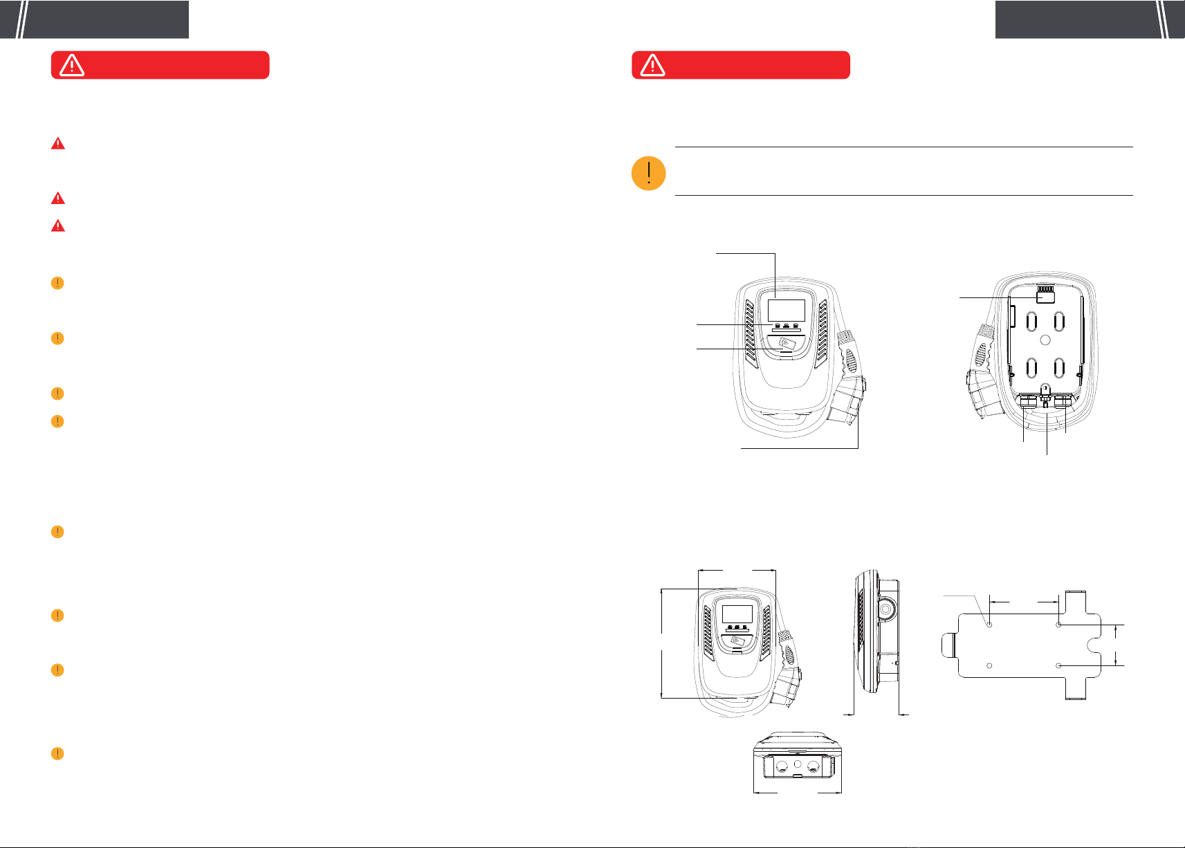
1.2 Installation Requirements
WARNING: Disconnect electrical power prior to installing the charging station.
WARNING: Be sure to preview the user manual and ensure local building and electrical codes are
reviewed before installing the AC charger.
WARNING: The AC charger should be installed by a qualified technician according to the user
manual and local safety regulations.
CAUTION: Use appropriate protection when connecting to the main power distribution cable.
CAUTION: Type B, C or D breaker with the rating current for table should be installed in the
upstream AC distribution box.
CAUTION: The device shall be mounted at height between 2 feet and 4 feet from ground.
CAUTION: Please keep the charger in a clean area with low humidity. Not recommended to be
installed in coastal environments with high humidity or high dust.
1.3 Daily Maintenance
CAUTION: Avoid moisture or water in the charger. If there is water or moisture ingress in the
charger, it is necessary to immediately power off to avoid immediate danger, and notify the
professionals to carry out maintenance before next use.
CAUTION: Please use the charger properly. Do not hit or press hard on the enclosure. If it is
damaged, please contact a professional technician.
CAUTION: Avoid placing the charger near hot objects and at high temperature locations and
away from dangerous substances such as flammable gases and corrosive materials.
CAUTION: Do not put heavy objects on the charger to avoid danger.
Circuit Breaker Options table
Output Amperage (A) 16A
20A
32A
40A
40A
50A
48A
60A
70A
90A
80A
100ACircuit Breaker Options (A)
USER MANUAL USER MANUAL

5 6
WARNING & CAUTION
2. Product Introductions
2.1 Basic Interface
2.2 Basic Dimension
WARNING & CAUTION
1.2 Exigence Avant L’installation
AVERTISSEMENT : Assurez-vous de consulter le manuel d'utilisation et assurez-vousque les
codes locaux du bâtiment et de l'électricité sont passés en revue avant d'installer le chargeur.
AVERTISSEMENT : Débranchez l'alimentation électrique avant d'installer la station decharge.
AVERTISSEMENT : Le chargeur CA doit être installé par un technicien qualifié conformément au
manuel d'utilisation et aux réglementations de sécurité locales.
MISE EN GARDE : Utilisez une protection appropriée lors de la connexion au câble de distribution
d'alimentation principal.
MISE EN GARDE : Un disjoncteur de type B, C ou D avec le courant nominal indiqué dans le
tableau doit être installé dans le boîtier de distribution CA en amont.
MISE EN GARDE : Cet appareil doit être monté à une hauteur entre 2 feet and 4 feet du sol.
MISE EN GARDE : Veuillez conserver le chargeur dans un endroit propre et peu humide. Il n’est
pas recommandé de l'installer dans des environnements côtiers à forte humidité ou à forte
poussière.
1.3 Entretien Quotidien
MISE EN GARDE : Évitez l'humidité ou l'eau dans le chargeur. En cas d'infiltration d'eau ou
d'humidité dans le chargeur, il est nécessaire de l'éteindre immédiatement pour éviter tout danger
immédiat et d'avertir le personnel professionnel d'effectuer l'entretien avant la prochaine utilisation.
MISE EN GARDE : Veuillez utiliser le chargeur correctement. Ne frappez pas ou n'appuyez pas
trop fort sur le boîtier. Si le boîtier est endommagé, veuillez contacter un technicien professionnel.
MISE EN GARDE : Évitez de placer le chargeur à proximité d'objets chauds et à des endroits à
haute température et loin de substances dangereuses telles que des gaz inflammables et des
matériaux corrosifs.
MISE EN GARDE : Ne placez pas d'objets lourds sur le chargeur pour éviter tout danger.
CAUTION: Avoid placing the charger near hot objects and at high temperature locations
and away from dangerous substances such as flammable gases and corrosive materials.
LED Light
Indication
4.3” LCD Screen
RFID Card
SAE J1772 AC Charging
Connector
Enclosure Wall-Mounted Bracket
9.8inch
13.8inch
Rear Notch
Charging Cable Inlet AC Power Inlet
LAN Cable Inlet
5.12inch
9.84inch
4-Φ0.35inch
2.83inch
4.8inch
USER MANUAL USER MANUAL

7
USER MANUAL USER MANUAL
3. Verify Contents
Check the box to ensure you have this installation guide and these parts:
Electric Vehicle AC Charger
Installation Instructions
1 2 3
4 5 6
7 8
8
2.3 Specifications
EVC10 Version
208/240VAC
16/32/40/48/70/80A
50-60 Hz
UVP, OVP, RCD, SPD, Ground Fault Protection
OCP, OTP, Control Pilot Fault Protection
SAE J1772AC Charging Connector
-40°F to 158°F
-22°F to 122°F
95% RH Maximum
95% RH Maximum
LAN Version /Wi-Fi Version/4G version
10M / 100M Base-T
802.11 b/g/n
GSM/3G/4G
18ft (25ft optional)
Type 3
Wall-Mounted
≤6561ft
Red, Green, Blue LED
Model Number
Rated Input Voltage
Rated Output Current
AC Power Frequency
Input Protection
Output Protection
Output Interface
Storage Temperature
Operation Temperature
Relative Operation Humidity
Relative Storage Humidity
Network Connection
Internet Function
Wi-Fi Function
3G/4G Function
Cable Length
Protection Level
Installation Type
Altitude
Status Indication

9
USER MANUAL USER MANUAL
4. Gather Tools
Tools required before installing the Wall-Mounted charger, gather the following tools:
1. Wire stripper
2. Adjustable Wrench
3. Voltmeter or digital multi-meter (for measuring AC voltage at the installation site)
4. Level
5. Pencil or marker
6. Drill
7. Phillips screwdriver
Note: The above tools are very important, please gather them all.
1 2 3
4 5 6 7
10
1 1
1
1
4
1
1
2
2
2
3
4
5
6
7
8
AC Charger With attached input power cable and
output charging cable
Please read carefully before use
For mounting the charging station to
the wall/structure
For securing the charging station to
the Mounting Bracket
For installing the Mounting Bracket
to the wall/structure
For tightening M5 Screws
For easy drilling of 4 screws holes
for wall-mounted bracket.
Control the charger start/stop
User Manual
Wall-Mounted Bracket
M5 Anti-Theft Round
Head Screws
M6 Hexagonal Expansion
Screws
Allen Wrench
Corrugated Mounting
Template
RFID Card (Optional)
Product Name DescriptionNo. Quantity

11 12
5. Plan The Mounting
WARNING: In areas with frequent thunderstorms, add surge protection at the service
panel for all circuits. Ensure all power and ground connections, especially those at the
breaker and bus bar, are clean and tight.
Tighten 13 screws on the front cover after the front
cover is put back, the recommended screw torque is
1.0 N.m (9.6 lbf.in) (for 4G Version).clean and tight.
Select the appropriate mounting location with electri calcapacity:
I. Ensure the owner has chosen a mounting location that
allows the charging cable to reach the car’s charging port
while still providing slack.
II. The device must be anchored into mounting such as
3.14’’ x 5.11’’ stud or a solid wall.
III. The device shall be mounted at height between 2 feet and 4 feet from ground.
Drill 4 Screw Holes with a diameter of 0.32’’and a depth
of 2.04’’ by using our mounting template. Please drill screw
holes in the direction of the template arrow.
CAUTION: Not recommended to be installed in coastal environments with high humidity
or high dust.
Use screwdriver to loosen the 13 fixed screws on the rear
of charger, then remove the front cover (for 4G Version).
USER MANUAL USER MANUAL
STEP 1 (Only for 4G Version)
STEP 3 (Only for 4G Version)
Insert the SIM card according to the picture's
instruction (for 4G Version).
STEP 2 (Only for 4G Version)
2
3
4
5
6
7
8
9
10
11
12
13 1
2
3
4
5
6
7
8
9
10
11
12
13 1
STEP 4
STEP 5
Wall-Mounted Bracket

13 14
6. Mount the Charging Station
Use 4 sets Hexagonal Expansion Screws to secure the
wall -mounted bracket on the wall. Then level the brackets.
Align the rear notch of charger with the
wall-mounted bracket and fit the screw holes of
the right and left side.
Tighten two M5 anti-theft screws to
complete the installation.
Overall outlook picture after installation.
Wall-mounted cable winding Optional cable hanging (optional accessory)
USER MANUAL USER MANUAL
STEP 4
STEP 1
STEP 2 STEP 3

15 16
7. Wire The Circuit
For safe use of electricity, please set circuit
breaker protection in the input part of EV Charger
The wiring is not complicated, just need to follow
the instructions below:
Connect the L1 lead to the grid L1, connect the L2
lead to the grid L2, connect the PE lead to the grid PE.
USER MANUAL USER MANUAL
WARNING: This device must be grounded. Disconnect electrical power prior to installing
the charging station.
CAUTION: Use appropriate protection when connecting to the main power distribution
cable.
WARNING: Improper connection of the equipment-grounding conductor would result in a
risk of electric shock. Check with a qualified electrician or serviceman if you are not sure
whether the product is properly grounded. Do not modify the plug provided with the
product – if it doesn’t fit the outlet, have a proper outlet installed by a qualified electrician.
8. Operate Your Device
8.1 Operating Steps with Plug and Charge
Standby Mode:
After being powered on,the lights will be all on, blue light (READY),green light (CHARGE)
and red light(FAULT).Then the blue light (READY) is constantly on in standby mode.
WARNING: This device should be supervised when used around children.
CAUTION: Do not put heavy objects on the charger to avoid danger.
CAUTION: Please use the charger properly. Do not hit or press hard on the enclosure. If
the case is damaged, please contact a professional technician.
Circuit Breaker Options table
Output Amperage (A)
Circuit Breaker Options (A)
16A
20A
32A
40A
40A
50A
48A
60A
70A
90A
80A
100A
STEP 1
READY

17 18
Charging finished: When the charging is finished,
the green light (CHARGE) is constantly on, pull out
the charging connector.
8.2 Operating Steps with RFID (Optional)
USER MANUAL USER MANUAL
Standby Mode:
After power-on, blue light (READY), green light (CHARGE) and red light (FAULT) all on. The blue light
(READY) is constantly on when in standby mode.
STEP 1
Ready to charge:
Please plug the charging connector into the vehicle charging inlet. When the green light (CHARGE) is
constantly on, the user can swipe the RFID Card.
STEP 2
Plug the Charging Connector:
Please plug the charging connector into the
vehicle charging inlet.
STEP 2
STEP 4
Charging:
The green light (CHARGE) turns to flash
automatically, charging is in process.
● If the red light (FAULT) is on, plug the vehicle
connector again.
● If red light is still on, please refer to "Error and
Warning Messages".
STEP 3
CHARGE
CHARGE
CAUTION: Please keep your RFID card properly to avoid unnecessary loss.
READY

19 20
Charging finished:
When the charging is finished or swipe your RFID
card, the green light (CHARGE) is constantly on.
Please press the button on connector and pull out
the charging connector.
Swipe the RFID Card:
Swipe the RFID card first and plug in the charging
connector within 120 seconds, otherwise you need
to swipe the RFID card again.
9. Light Codes
USER MANUAL USER MANUAL
STEP 3
STEP 5
Charging:
The green light (CHARGE) turns to flash automatically,
charging is in process.
● If the red light (FAULT) is on, plug in the charging
connector again.
● If red light is still on, please refer to "Error and
Warning Messages".
STEP 4
CHARGE
CHARGE
9.1 After Start UP
9.2 Error and Warning Messages
Remark
Auto Recover
Auto Recover
Auto Recover
Auto Recover
Auto Recover
Auto Recover
Auto Recover
Red
1 flashes followed by 3 sec pause
2 flashes followed by 3 sec pause
3 flashes followed by 3 sec pause
4 flashes followed by 3 sec pause
5 flashes followed by 3 sec pause
6 flashes followed by 3 sec pause
Flicker
Constantly Bright
Constantly Bright
Constantly Bright
Rotate to Reset Emergency Button
Contact Customer Service
Status
Input OVP
Input UVP
Output OCP
OTP
RCD Abnormal
Ground Fault
Control Pilot Fault
Emergency Fault
Constantly Bright Contact Customer ServiceMCU Self-Test Fail
Constantly Bright Contact Customer ServiceRCD Self-Test Fail
Constantly Bright Contact Customer Service
Relay Self-Test Fail
Constantly Bright Contact Customer ServiceRCD Abnormal Stop Charging
Output OCP Stop Charging
OTP Stop Charging
Standby,
waiting to plug
in
Waiting to
charge,
communicating
with vehicle
Charging in
progress
Finished
charging Fault
Solid Blue Solid Green Green Blinking Solid Green Solid Red

21 22
USER MANUAL USER MANUAL
10. Warranty and Maintenance
• The warranty period for this charger is three years.
• During the warranty period for any malfunction under normal use according to the User Manual
(to be determined by certified maintenance technicians of sellers), the product shall be repaired free of
charge. Except for the following situations, the charger shall be subject to the above warranty terms:
1. The warranty certificate cannot be provided or the contents of the warranty certificate are modified
or inconsistent with the label indication of the repaired product.
2. Those who are unable to provide valid proof of purchase.
3. Those who exceed the manufacturer's specified warranty period.
4. Those who damage the product due to not following the product service instruction for use,
maintenance and storage.
5. Damage or malfunction caused by external object entering.
6. Unauthorized repair, disassembly or modification.
7. Damage caused by force majeure (such as lightning, excessive voltage, earthquake, fire, flood,etc.).
8. Malfunction and damage caused by other unavoidable external factors. Malfunction and damage
caused by improper use of equipment, such as water or other solutions entering into the equipment.
9. Malfunction and damage caused by the grid power supply and voltage which is not specified for use
with the charger equipment.
The above guarantees shall be made solely, and no other express or implied warranties shall be made
(including the implied warranties of merchant ability, particular and applicable reason- ableness and
adaptability, etc.) whether in the contract, civil negligence, or other aspects, the Company shall not be
responsible for any special, incidental or consequential damages.
Table of contents
Popular Batteries Charger manuals by other brands

Altronix
Altronix LPS3WP12 installation guide

Associated Equipment
Associated Equipment US20 Operator's manual

Clas Ohlson
Clas Ohlson V-3150-UK instruction manual

Leviton
Leviton T5633 quick start guide

Supra
Supra DisplayKEY installation instructions

EggTronic
EggTronic Wireless Charging Pad 2X DPWH10 user manual

Hawker
Hawker EnerSys LifeSpeed IQ Safety and use instructions

Schumacher
Schumacher XC75 owner's manual

Common Sense RC
Common Sense RC Lectron Pro Power Mini instruction manual

Medion
Medion AutoXS MD 18559 user manual

MSW
MSW S-CHARGER-6V12-10A user manual

Mastervolt
Mastervolt MASS 24/50-2 installation manual