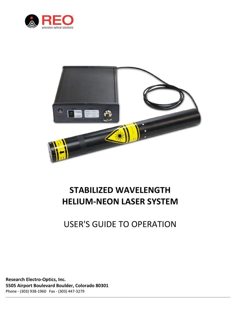
REO 32734 Quick start guide

VISIBLE WAVELENGTH
HELIUM-NEON LASER SYSTEM
USER'S GUIDE TO OPERATION
Research Electro-Optics, Inc.
5505 Airport Boulevard Boulder, Colorado 80301
Phone - (303) 938-1960 Fax - (303) 447-3279
_______________________________________________________________________________________________________________________________

REF-177
UNPACKING................................................................................................................................................................. 3
SHIPPING INVENTORY ................................................................................................................................................. 3
SAFETY INFORMATION ................................................................................................................................................ 3
COMPLIANCE............................................................................................................................................................... 5
FIGURE 1: LASER HEAD LABEL PLACEMENT DIAGRAM................................................................................................................. 6
FIGURE 2: POWER SUPPLY LABEL PLACEMENT DIAGRAM............................................................................................................. 6
OPERATING INSTRUCTIONS FOR POWER SUPPLIES ..................................................................................................... 7
FIGURE 3: FRONT PANEL OF POWER SUPPLY ............................................................................................................................. 7
FIGURE 4: BACK PANEL OF POWER SUPPLY ............................................................................................................................... 8
FIGURE 5: CONFIGURING INPUT LINE VOLTAGE SELECTOR ............................................................................................................ 8
FIGURE 6: CONFIRMING SELECTED VOLTAGE ............................................................................................................................. 9
FIGURE 7: TWO POSITION SHUTTER ASSEMBLY ........................................................................................................................ 10
OPERATING INSTRUCTIONS FOR LASER HEAD WITH POWER SUPPLY ........................................................................ 10
BASIC TROUBLESHOOTING ........................................................................................................................................ 10
PRODUCT WARRANTY STATEMENT ........................................................................................................................... 11
EU DECLARATION OF CONFORMITY........................................................................................................................... 13

REF-177
3
UNPACKING
•Inspect the packing container for any damage that may have occurred during shipment.
•Contact the shipper immediately if the laser or power supply has been damaged during
shipping.
•Packing materials are specifically designed to protect against shipping damage.
•Carefully remove the laser system from the packing container.
•Inspect for damage including dents, scratches, or broken glass within the laser housing.
•Contact retailer immediately if the laser head or power supply appears to be damaged.
SHIPPING INVENTORY
The equipment included in this shipment will match the packing slip attached to the box. Verify
that the correct product was shipped to you by matching the serial number(s) on the packing list.
Notify retailer immediately if the shipment is incomplete or if an incorrect item was shipped.
Note: Please keep and store all packaging materials received with your product in case a return
needs to be made.
This package contains the following:
1 –Cylindrical Laser Head
1 –Power supply
2 –Keys
1 –Remote Interlock Connector
1 –Fuse Assembly, Fuse, and Manual Voltage Selector
1 –115V Power Cord
1 –230V Power Cord
SAFETY INFORMATION
This laser is safe to operate provided that the user complies with all safety warnings. It is
recommended that all personnel who will operate or be in the vicinity of the laser during operation
read and be familiar with this manual as well as be made aware of the following safety warnings.
•Alterations, modifications, or improper installation can result in shock, visible
and/or infrared radiation exposure, and void of the warranty in part or entirety.
•Ensure that the laser head is securely connected to the power supply. To
prevent faulty operation make sure that the male connector is fully
seated in the back of the power supply.
•The helium neon laser can collect charge during operation acting as a
capacitor. Once the power supply is turned off, best practice is to leave
the high voltage cable connected to the power supply. If the high voltage
cable is removed from the power supply the prongs should be shorted

REF-177
4
together to discharge any remaining energy. A way to accomplish this is
to simultaneously touch both prongs to a conductor.
•Do not attempt to open the sealed laser housing or the power supply.
The power supply and laser is not user accessible and service operations
inside the enclosure must only be performed by authorized and trained
personnel. Opening the laser or power supply will result in loss of
warranty.
•Avoid direct exposure to the laser beam.
•Laser emissions can be hazardous to the eyes.
•Never look directly into the laser light source or at scattering laser light
from reflective surfaces.
•Never sight down the beam into the source of the laser emissions.
•Install the laser so that the laser beam is not at eye level.
•Whenever the laser is operating and the beam is not in use, block the
beam with the shutter on the output aperture.
•As a precaution against accidental exposure to either the laser beam or
its reflection, operators need to wear laser safety glasses designed for
this type of laser.
Table 1: Recommended Eyewear Optical Density, Maximum Permissible Exposure, and Nominal
Ocular Hazard Distance by Part Number.
Part Number Description
Recommended Eyewear
Optical Density (OD)
Maximum Permissible
Exposure (MPE) W/cm2
Nominal Ocular
Hazard Distance (NOHD) (m)
32734 LASER SYSTEM, 633nm, STBLZD, >1.5mW 0.28 0.0026 5.63
32172 LASER SYSTEM, 3.39µm, 2.0mW, POL 0 0.1 0
30990 LASER SYSTEM, 633nm, 5.0mW, RANDOM 0.74 0.0026 13
30025 LASER SYSTEM, 633nm,1.5mW,POL, 9.5" 0.3 0.0026 5.63
TUNABLE LASER, 633nm,4.0 mW, POL 0.74 0.0026 13
TUNABLE LASER, 612nm, 2.5 mW,POL 0.48 0.0026 7.02
TUNABLE LASER, 604nm,0.5 mW, POL 0 0.0026 0
TUNABLE LASER, 594nm, 0.6 mW,POL 0.18 0.0026 3.68
TUNABLE LASER, 543nm,0.3 mW,POL 0 0.0026 0
31007 LASER SYSTEM, 633nm, 0.8mW, POL 0 0.0026 0
31008 LASER SYSTEM, 633nm, 0.5mW, RAN 0 0.0026 0
30968 LASER SYSTEM, 543nm, 0.5mW, POL 0 0.0026 0
30993 LASER SYSTEM, 633nm, 12.0mW, POL 1.08 0.0026 19.3
33361 LASER SYSTEM, 543nm, 1.5mW, POL 0.3 0.0026 5.63
30967 LASER SYSTEM, 543nm, 0.5mW, RAN 0 0.0026 0
30988 LASER SYSTEM, 633nm, 2.0mW, RAN 0.48 0.0026 7.02
33141 LASER SYSTEM, 1.52UM, 1.0mW, POL 0 0.1 0
30992 LASER SYSTEM, 633nm, 12.0mW, RANDOM 1.08 0.0026 19.3
39582 LASER SYSTEM, 594nm, 2.0mW, POL 0.48 0.0026 7.02
39635 LASER SYSTEM, 633nm, 17.0mW, RANDOM 1.23 0.0026 24.8
38766 LASER SYSTEM, 633nm, STABILIZED, AP 0.26 0.0026 5.63
39727 LASER SYSTEM, 633nm, STBLZD, >1.2mW 0.15 0.0026 3.68
39581 LASER SYSTEM, 543nm, 1.0mW, POL 0.11 0.0026 3.68
40094 LASER SYSTEM, 594nm, 1.0mW, POL 0.18 0.0026 3.68
40138 Laser System, 1.15/3.39µm, 5.0mW, POL 0/0 .0059/.1 0/0
40137 Laser System, 1523/633nm, 1.0mW, POL 0/0 0.1/.0026 0/3.68
40136 Laser System, 1.15um, 1.0mW, Pol 0 0.0059 0
40141 Laser System, 543nm, 0.5mW, Multimode 0 0.0026 0
14309 LASER SYSTEM,633nm,35mW,POL 1.58 0.0026 36.4
14354 Laser System, 633nm, 3.0mW, ORTHOG POL , OPIS 0.54 0.0026 9.15
39568 Laser System, 543nm, 1.0mW, RAN 0.11 0.0026 3.68
Calculations performed by "The Evaluator" From Laser Institute of America, INC. www.lia.org
30602/30603

REF-177
5
•High voltage is present at all times when the key switch on the control
box is in the “ON” position.
•The power cord and plug are provided with a ground line. To avoid
possible shock ensure that the plug is properly connected to a ground
point at the electrical connection.
•Do not perform any operating or maintenance procedure that is not
described in the user’s manual as shock or injury may result.
•Do not operate this product if the cover has been removed.
•This product is for indoor use only. To prevent potential fire or shock
hazard, do not expose the unit to any source of excessive moisture.
•Disconnect power cord before replacing fuses.
•Clean laser head and power supply with dry, soft cloth. Do not use
liquids.
CAUTION: Use of controls or adjustments, or performance of procedures other than those specified herein
may result in hazardous radiation exposure. Avoid unnecessary exposure to laser or collateral radiation that
exceeds the accessible emission limits as determined by the National Center for Devices and Radiological
Health (CDRH). Unauthorized modifications to the laser or power supply may cause irreversible damage to
the system, as well as result in possible hazardous radiation exposure. These modifications will void all
warranties.
COMPLIANCE
Each Helium-Neon laser system that is certified to be in compliance with the CDRH regulations,
is equipped with a key-switch, remote interlock connector, emission indicator, time delay relay
(built into the power supply), a shutter (located in the front bezel of the laser housing), and all
appropriate warning labels.
Below are examples of compliance symbols and approximate placement on the laser head (Figure
1) and the power supply (Figure 2).
A. Laser Head Manufacturing Label Includes the Following:
•Model Number
•Date of Manufacture
•Minimum Specified Power Rating
•Maximum Power Rating
•Wavelength
•Serial Number
•Mandatory Compliance Symbols and Conformance Labels
B. International Laser Beam Hazard Symbol
C. Safety Warning and Laser Class Call-Out
D. Laser Aperture Identification/Warning
E. Caution Label for Voltage Input Selector
F. Power Supply Manufacturing Label Includes the Following:
•Model Number

REF-177
6
•Power
•Date of Manufacture
•Serial Number
G. Power Supply Manufacturing Label Includes the Following:
•Model Number
•Serial Number
•Input Power
•Replacement Fuse Information
Figure 1: Laser Head Label Placement Diagram
Figure 2: Power Supply Label Placement Diagram

REF-177
7
Research Electro-Optics (REO) certifies that our laser heads and lab power supplies meet the
appropriate CE requirements. For the CE regulations to be met, all lab power supplies must be
used with an input line cord with a length of less than 3 meters.
The below symbol on the product or on its packaging indicates that this product must not be
disposed of with regular waste. It is the user responsibility to dispose of waste equipment
according to the local laws. The separate collection and recycling of the waste equipment at the
time of disposal will help to conserve natural resources and ensure that it is recycled in a manner
that protects human health and the environment. For further information about where the user
OPERATING INSTRUCTIONS FOR POWER SUPPLIES
The power supply is key switch operated. It incorporates all of the appropriate safety features
required by international regulations.
Figure 3: Front Panel of Power Supply

REF-177
8
Figure 4: Back Panel of Power Supply
Fuse Assembly/Power Cord Installation
The power supply will not operate until the fuse assembly is correctly installed. The enclosed
fuse assembly can be found with a 250V - 5A slow blow fuse installed. A component within this
fuse assembly is the input line voltage selector. The input line voltage selector configures the
correct input line voltage for the local environment. This can be accomplished by sliding the input
line voltage selector into the side of the fuse assembly (Figure 5). The desired input line voltage
can be seen right side up in the window on the face of the fuse assembly. Select the proper voltage
for your region of the world. Once the correct line voltage is selected, insert the fuse assembly into
the power cord connector located on the back of the unit. The fuse assembly will be flush with the
face of the AC connector when properly installed.
Note: Use only 250V-5A slow blow fuses with this product (5mm dia x 20mm length). Failing to
select the correct input line voltage will result in failure of the unit and will void the warranty.
Figure 5: Configuring Input Line Voltage Selector

REF-177
9
Once the fuse assembly and voltage selector are correctly installed, insert the supplied US
IEC320 Female to Nema 5-15P power cord into the power supply unit. To ensure proper and
optimal laser operation, only use the power supply that is appropriate for the HeNe laser head in
use.
Figure 6: Confirming Selected Voltage
Fuse Replacement
To remove the fuse assembly, insert a flat blade screw driver into the groove on top of the fuse
assembly and carefully remove from the power cord connector. Remove the fuse and replace with
a 250V-5A slow blow fuse (Fuse Type 2AG). While replacing the fuse assembly as described above,
ensure that the input voltage selector is still properly configured.
Remote Interlock Operation
To use the remote interlock connector, remove the shorting conductor from the connector
provided. The connector may then be wired into the interlock system. The circuit is designed to
activate the laser output when the two contacts of the connector are shorted together. This can be
achieved via a simple switch or with relay contacts.
The voltage on this connector is nominally 5VDC and is generated internally within the power
supply unit. It is completely isolated from the AC line voltage. Failure of the remote interlock
feature due to improper application of external voltages is not covered by warranty.
Operating Procedures
The system is equipped with a key switch located on the front panel. This is used by the
customer to activate and deactivate the laser. The emissions indicator on the front panel will come
on to warn of imminent laser emission. A 10-15 second delay will begin after the key switch is
turned to the “ON” position. The laser system will be “OFF” when the key is in the vertical position.
The laser emissions can be controlled from the remote interlock connector. If the factory
supplied remote interlock plug is removed while the laser is in operation, laser emissions will cease
immediately. If the remote interlock plug is inserted into the remote interlock connector, laser
emissions will resume after a 10-15 second safety delay. If the remote interlock connector has
been interfaced to external circuits, laser emissions will be controlled in a similar manner.
•The system will start within 10-15 seconds after engaging the key switch.
•Laser intensity will stabilize at or above the specified power output after thirty minutes of
continuous operation.
•Open the beam shutter located on the laser head at the output of the laser (indicated by
the arrow on the aperture label).

REF-177
10
Figure 7: Two Position Shutter Assembly
Maintenance & Service
The power supply unit contains no user serviceable parts. Return the power supply unit to
Newport for any service issues that may arise.
OPERATING INSTRUCTIONS FOR LASER HEAD WITH POWER SUPPLY
The cylindrical construction of the laser head allows for easy mounting in ring clamps, V-blocks,
or similar mounting hardware without affecting the laser's alignment. Use caution when clamping
onto the laser as too much pressure can damage the aluminum housing or cause misalignment.
The front bezel has four each 4-40 Unified National Coarse Thread (UNC) holes to secure an
optional accessory mounting ring. The ring (part number R-30646), which is available for purchase
from Research Electro-Optics, has 1" diameter, 32 threads-per-inch (TPI) female threads.
Installation
Laser system includes a laser head and a power supply.
•Configure the AC power supply as directed in the “Operating Instructions for Power
Supplies” section above.
•Insert the remote interlock connector into the back of the power supply.
•Plug the two prong high voltage cable from the laser into the front of the power supply.
Confirm that the plug is well seated.
•Insert the key into the front panel of the power supply.
BASIC TROUBLESHOOTING
Once the laser and power supply have been properly connected, the laser system will operate
without maintenance. Below are some guidelines if your system is not operating. When
troubleshooting take all precautions as if the laser system is fully operational.

REF-177
11
•No emission light above the key switch after key has been turned to the on position:
oVerify that the power cord is connected to the back of the power supply as well as a
verified power source.
oVerify that the remote interlock is fully engaged in the back panel of the power
supply.
•No laser emission:
oVisually verify that the high voltage cable is connected and well seated to the front
of the power supply.
oVerify the shutter is open.
oIf laser does not ignite within one minute switch the control box off, wait several
minutes and retry.
PRODUCT WARRANTY STATEMENT
Research Electro-Optics (REO) lasers and power supplies are warranted for twelve (12) months
from the date of shipment. Items will be free from defects in material and workmanship, and will
conform to the specifications provided on the REO website and published specification sheets,
under normal use and service when correctly installed and maintained. REO will either repair or
replace (at REO’s sole option) any defective or nonconforming Product or part thereof which is
returned at Buyer’s expense to REO’s facility, provided, that Buyer notifies REO in writing promptly
after discovery of the defect or nonconformity and within the Warranty Period.
Repairs made or Products or components replaced under warranty are warranted for the
remaining unexpired duration of the original Warranty Period for such Products or components.
REO’s standard repair charges shall be applicable forproducts returned for repair that are not
covered under warranty. Out-of-warranty repairs are warranted for ninety (90) days from date of
shipment of the repaired Product.
The foregoing warranty does not apply to Products or components thereof which are (a)
repaired, modified or altered by any party other than REO; (b) used in conjunction with equipment
not provided or authorized by REO; (c) subjected to unusual physical, thermal, electrical or optical
stress, improper installation, misuse, abuse, tampering, accident, contamination, or negligence in
use, storage, transportation or handling; or (d) considered a consumable item or an item requiring
repair or replacement due to normal wear and tear. The foregoing warranty will also not apply if
the “Warranty Void If Broken” seal located on any Product has been removed, broken or otherwise
tampered with. On-site warranty repair is not covered under the foregoing warranty.
THE FOREGOING WARRANTY IS EXCLUSIVE AND IN LIEU OF ALL OTHER WARRANTIES. EXCEPT AS
EXPRESSLY PROVIDED HEREIN, REO MAKES NO WARRANTIES, EITHER EXPRESS OR IMPLIED, EITHER IN FACT
OR BY OPERATION OF LAW, STATUTORY OR OTHERWISE, REGARDING THE PRODUCTS, SOFTWARE OR
SERVICES. REO EXPRESSLY DISCLAIMS ANY IMPLIED WARRANTIES OF MERCHANTABILITY OR FITNESS FOR A
PARTICULAR PURPOSE FOR THE PRODUCTS, OR SERVICES. THE OBLIGATIONS OF REO SET FORTH IN THIS
PARAGRAPH SHALL BE REO’S SOLE LIABILITY, AND BUYER’S SOLE REMEDY, FOR BREACH OF THE FOREGOING
WARRANTY. End

REF-177
12
Warranty Procedure
Products may only be returned by Buyer when accompanied by a return material authorization
number (“RMA#”) issued by REO’s Customer Support Center, with freight prepaid by Buyer. REO
will not be responsible for any damage occurring in transit or obligated to accept Products
returned for warranty repair without a RMA#. Buyer bears all risk of loss or damage to the
Products until delivery at REO’s designated facility. REO will pay for shipment back to Buyer for
Products repaired under warranty.
Note: HeNe lasers are constructed from glass vacuum tubes and are very fragile. REO strongly
recommends taking appropriate precautions in preparing your laser for shipment. Make sure the
tube is well padded (equivalent to 3 inch thick high density foam on all sides) and insure that the
power supply and tube are secured within the box so they do not move during shipment. REO will
not assume responsibility for any shipping damages unless the laser is sent in REO-supplied
packaging. REO will provide appropriate shipping materials at cost if you do not have the original
shipping materials.
To request a RMA#, contact REO’s Customer Support Center at:
Phone- (303) 938-1960
Fax- (303-447-3279)
Email- [email protected]
Following the receipt of your assigned RMA number return the product to Research Electro-Optics
in the proper packaging with freight prepaid. Please, clearly mark the assigned RMA number on the
outside of the packaging with the address as follows:
Research Electro-Optics, INCRMA# (Assigned RMA Number)
5505 Airport Blvd Boulder, CO 80301 USA

REF-177
13
EU DECLARATION OF CONFORMITY
CE Compliance refers to following model numbers:
Year mark verified: 2016
Type of Equipment: Electrical equipment for measurement, control and laboratory use in industrial
locations.
Manufacturer: Research Electro-Optics, Inc.
5505 Airport Blvd.
Boulder, CO, 80301
United States of America
Compliance was demonstrated to the following standards:
•IEC/EN 60825-1 | Laser Safety
•IEC/EN 61010-1 | Electrical Safety
•IEC/EN61326 | EMC
Note: The lasers listed in the table are designed to operate in a controlled electromagnetic environment; i.e., industrial
laboratory settings. Lasers may interfere with R.F. communications such as mobile telephones and wireless networks.
Brian P. Turner
Product Line Manager
Research Electro-Optics, Inc.
5505 Airport Blvd
Boulder, CO 80301 USA
Part Number Description
32734 LASER SYSTEM, 633NM, STBLZD, >1.5MW
32172 LASER SYSTEM, 3.39UM, 2.0MW, POL
30990 LASER SYSTEM, 633NM, 5.0MW, RANDOM
30025 LASER SYSTEM, 633NM,1.5MW,POL, 9.5"
31007 LASER SYSTEM, 633NM, 0.8MW, POL
31008 LASER SYSTEM, 633NM, 0.5MW, RAN
30968 LASER SYSTEM, 543NM, 0.5MW, POL
30993 LASER SYSTEM, 633NM, 12.0MW, POL
33361 LASER SYSTEM, 543NM, 1.5MW, POL
30967 LASER SYSTEM, 543NM, 0.5MW, RAN
30988 LASER SYSTEM, 633NM, 2.0MW, RAN
33141 LASER SYSTEM, 1.52UM, 1.0MW, POL
30992 LASER SYSTEM, 633NM, 12.0MW, RANDOM
39582 LASER SYSTEM, 594NM, 2.0MW, POL
39635 LASER SYSTEM, 633NM, 17.0MW, RANDOM
38766 LASER SYSTEM, 633NM, STABILIZED, AP
39727 LASER SYSTEM, 633NM, STBLZD, >1.2MW
39581 LASER SYSTEM, 543NM, 1.0MW, POL
40094 LASER SYSTEM, 594NM, 1.0MW, POL
40138 Laser System, 1.15/3.39um, 5.0mW, POL
40137 Laser System, 1523/633nm, 1.0mW, POL
40136 Laser System, 1.15um, 1.0mW, Pol
40141 Laser System, 543nm, 0.5mW, Multimode
14309 LASER SYSTEM,633NM,35MW,POL
14354 Laser System, 633nm, 3.0mW, ORTHOG POL , OPIS
39568 Laser System, 543nm, 1.0mW, RAN
Other manuals for 32734
2
This manual suits for next models
27
Table of contents
Other REO Measuring Instrument manuals
Popular Measuring Instrument manuals by other brands

Electroswitch
Electroswitch 25-1000 Operation manual

Triplett
Triplett PQC300 user manual

Endress+Hauser
Endress+Hauser Proline Promag 50H technical information

PCB Piezotronics
PCB Piezotronics ICP S112A23 Installation and operating manual

Hanna Instruments
Hanna Instruments pHep+ HI 98108 instruction manual

Tormach
Tormach 31101 Technical document