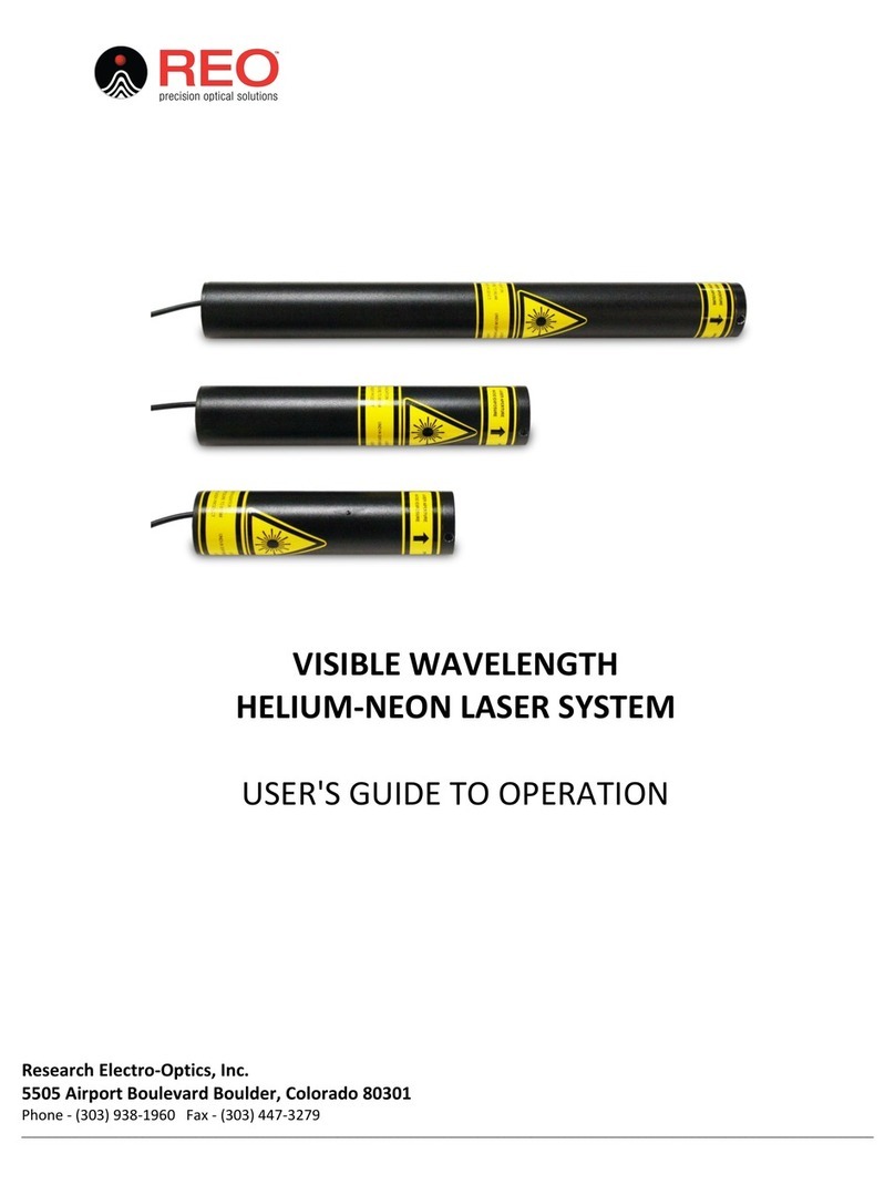
REO 32734 Quick start guide

LINE TUNABLE
HELIUM-NEON LASER SYSTEM
USER'S GUIDE TO OPERATION
Research Electro-Optics, Inc.
5505 Airport Boulevard Boulder, Colorado 80301
Phone - (303) 938-1960 Fax - (303) 447-3279
_______________________________________________________________________________________________________________________________

REF-174
UNPACKING......................................................................................................................................................3
SHIPPING INVENTORY.....................................................................................................................................3
SAFETY INFORMATION...................................................................................................................................3
TABLE 1: EYEWEAR OPTICAL DENSITY,MAXIMUM PERMISSIBLE EXPOSURE,AND NOMINAL OCULAR HAZARD DISTANCE. ........................ 4
FIGURE 1: LINE TUNABLE LASER LABEL PLACEMENT DIAGRAM ...................................................................................................... 5
LASER SYSTEM................................................................................................................................................6
FIGURE 2: BACK PANEL OF LASER SYSTEM................................................................................................................................. 6
OPERATION ......................................................................................................................................................6
FIGURE 3: COLOR SELECTOR AND TRANSVERSE ADJUSTMENT VALUES ON LABEL............................................................................... 7
FIGURE 4: INPUT VOLTAGE CALL-OUT ON LABEL ........................................................................................................................ 8
FIGURE 5: TWO POSITION SHUTTER ADJUSTMENT ...................................................................................................................... 8
FIGURE 6: REMOTE PLUG PROPERLY INSTALLED ......................................................................................................................... 9
FIGURE 7: FUSE REPLACEMENT ............................................................................................................................................... 9
PRODUCT WARRANTY STATEMENT.............................................................................................................9
EU DECLARATION OF CONFORMITY..........................................................................................................11

REF-174
3
UNPACKING
•Inspect the packing container for any damage that may have occurred during shipment.
•Contact the shipper immediately if the laser or control box has been damaged during
shipping.
•Packing materials are specifically designed to protect against shipping damage.
•Carefully remove the laser system from the packing container.
•Inspect for damage including dents, scratches, or broken glass within the laser housing.
•Contact retailer immediately if the laser system appears to be damaged.
SHIPPING INVENTORY
The equipment included in this shipment will match the packing slip attached to the box. Verify
that the correct product was shipped to you by matching the serial number(s) on the packing list.
Notify retailer immediately if the shipment is incomplete or if an incorrect item was shipped.
Note: Please keep and store all packaging materials received with your product in case a return needs to be
made.
This package contains:
1 –Line Tunable Laser System
2 –Keys
1 –Remote Interlock Connector
1 –115V Power Cord or 230V Power Cord
SAFETY INFORMATION
This laser is safe to operate provided that the user complies with all safety warnings. It is
recommended that all personnel who will operate or be in the vicinity of the laser during operation
read and be familiar with this manual as well as be made aware of the following safety warnings.
•Alterations, modifications, or improper installation can result in shock, visible
and/or infrared radiation exposure, and void of the warranty in part or entirety.
•Do not attempt to open the sealed laser system. The laser system is not
user accessible and service operations inside the enclosure must only be
performed by authorized and trained personnel. Opening the laser
system will result in loss of warranty.
•Avoid direct exposure to the laser beam.
•Laser emissions can be hazardous to the eyes.
•Never look directly into the laser light source or at scattering laser light
from reflective surfaces.
•Never sight down the beam into the source of the laser emissions.
•Install the laser so that the laser beam is not at eye level.

REF-174
4
•Whenever the laser is operating and the beam is not in use, block the
beam with the shutter on the output aperture.
•As a precaution against accidental exposure to either the laser beam or
its reflection, operators need to wear laser safety glasses designed for
this type of laser.
Table 1: Recommended Eyewear Optical Density, Maximum Permissible Exposure, and Nominal
Ocular Hazard Distance by Newport Part Number.
•High voltage is present at all times when the key switch is in the “ON”
position.
•The power cord and plug are provided with a ground line. To avoid
possible shock ensure that the plug is properly connected to a ground
point at the electrical connection.
•Do not perform any operations or maintenance procedure that is not
described in the user’s manual as shock or injury may result.
•Do not operate this product if the cover has been removed.
•This product is for indoor use only. To prevent potential fire or shock
hazard, do not expose the unit to any source of excessive moisture.
•Disconnect power cord before replacing fuses.
•Clean exterior of laser system with a dry, soft cloth. Do not use liquids.
CAUTION: Use of controls or adjustments, or performance of procedures other than those specified herein
may result in hazardous radiation exposure. Avoid unnecessary exposure to laser or collateral radiation that
exceeds the accessible emission limits as determined by the National Center for Devices and Radiological
Health (CDRH). Unauthorized modifications to the laser or power supply may cause irreversible damage to
the system, as well as result in possible hazardous radiation exposure. These modifications will void all
warranties.
Part Number Description
Recommended Eyewear
Optical Density (OD)
Maximum Permissible
Exposure (MPE) W/cm2
Nominal Ocular
Hazard Distance (NOHD) (m)
32734 LASER SYSTEM, 633nm, STBLZD, >1.5mW 0.28 0.0026 5.63
32172 LASER SYSTEM, 3.39µm, 2.0mW, POL 0 0.1 0
30990 LASER SYSTEM, 633nm, 5.0mW, RANDOM 0.74 0.0026 13
30025 LASER SYSTEM, 633nm,1.5mW,POL, 9.5" 0.3 0.0026 5.63
TUNABLE LASER, 633nm,4.0 mW, POL 0.74 0.0026 13
TUNABLE LASER, 612nm, 2.5 mW,POL 0.48 0.0026 7.02
TUNABLE LASER, 604nm,0.5 mW, POL 0 0.0026 0
TUNABLE LASER, 594nm, 0.6 mW,POL 0.18 0.0026 3.68
TUNABLE LASER, 543nm,0.3 mW,POL 0 0.0026 0
31007 LASER SYSTEM, 633nm, 0.8mW, POL 0 0.0026 0
31008 LASER SYSTEM, 633nm, 0.5mW, RAN 0 0.0026 0
30968 LASER SYSTEM, 543nm, 0.5mW, POL 0 0.0026 0
30993 LASER SYSTEM, 633nm, 12.0mW, POL 1.08 0.0026 19.3
33361 LASER SYSTEM, 543nm, 1.5mW, POL 0.3 0.0026 5.63
30967 LASER SYSTEM, 543nm, 0.5mW, RAN 0 0.0026 0
30988 LASER SYSTEM, 633nm, 2.0mW, RAN 0.48 0.0026 7.02
33141 LASER SYSTEM, 1.52UM, 1.0mW, POL 0 0.1 0
30992 LASER SYSTEM, 633nm, 12.0mW, RANDOM 1.08 0.0026 19.3
39582 LASER SYSTEM, 594nm, 2.0mW, POL 0.48 0.0026 7.02
39635 LASER SYSTEM, 633nm, 17.0mW, RANDOM 1.23 0.0026 24.8
38766 LASER SYSTEM, 633nm, STABILIZED, AP 0.26 0.0026 5.63
39727 LASER SYSTEM, 633nm, STBLZD, >1.2mW 0.15 0.0026 3.68
39581 LASER SYSTEM, 543nm, 1.0mW, POL 0.11 0.0026 3.68
40094 LASER SYSTEM, 594nm, 1.0mW, POL 0.18 0.0026 3.68
40138 Laser System, 1.15/3.39µm, 5.0mW, POL 0/0 .0059/.1 0/0
40137 Laser System, 1523/633nm, 1.0mW, POL 0/0 0.1/.0026 0/3.68
40136 Laser System, 1.15um, 1.0mW, Pol 0 0.0059 0
40141 Laser System, 543nm, 0.5mW, Multimode 0 0.0026 0
14309 LASER SYSTEM,633nm,35mW,POL 1.58 0.0026 36.4
14354 Laser System, 633nm, 3.0mW, ORTHOG POL , OPIS 0.54 0.0026 9.15
39568 Laser System, 543nm, 1.0mW, RAN 0.11 0.0026 3.68
Calculations performed by "The Evaluator" From Laser Institute of America, INC. www.lia.org
30602/30603

REF-174
5
Each helium-neon laser system that is certified to be in compliance with the CDRH regulations,
is equipped with a key-switch, remote interlock connector, emission indicator, time delay relay
(built into the laser system), a beam attenuator (or shutter, located in the front bezel of the laser
housing), and all appropriate warning labels.
Below are examples of compliance symbols and approximate placement on the body of the line
tunable laser assembly.
A. Laser Manufacturing Label Includes the Following:
•Model Number
•Date of Manufacture
•Minimum Specified Power Rating Per Wavelength
•Maximum Power Rating Per Wavelength
•Wavelengths
•C-Value: Color Selector Value
•T-Value: Transverse Selector Value
•Serial Number
B. International Laser Beam Hazard Symbol
C. Safety Warning and Laser Class Call-Out
D. Laser Aperture Identification/Warning
Figure 1: Line Tunable Laser Label Placement Diagram

REF-174
6
LASER SYSTEM
The line tunable laser system comes packaged in an aluminum housing which contains all of the
components of the system. The housing is equipped with a sliding beam attenuator (or shutter)
mounted to the front panel. The shutter assembly has four each 4-40 Unified National Course
Thread (UNC) holes to secure the optional accessory mounting ring. The ring (part number 30646),
which is available for purchase from Research Electro-Optics, incorporates 1” diameter, 32
threads-per-inch (TPI) female threads. The back panel of the laser system contains the key-switch,
remote interlock connector, fuse access, the color adjustment knobs, and a three-foot long power
cord for connecting to either 115 VAC (System Model Number 30602) or 230 VAC (System Model
Number 30603) input power.
Figure 2: Back Panel of Laser System
Assembly of Laser System
•Plug the laser AC power cord into the power connector on the back panel.
•With the key switch in the “OFF” (vertical) position, plug the AC power cord into an
appropriate power source.
•Insert the remote plug into the interlock receptacle.
OPERATION
•Turn the key switch to the “ON” (horizontal) position and the emission indicator LED will
illuminate.
•Slide the two position shutter assembly to the “ON” position.
•Use a neutrally colored diffusively reflective card (e.g. card stock) or panel placed
approximately 10” (25cm) in front of output aperture in order to see lasing beam while
adjustments are made.

REF-174
7
•Turn both the color selector knob and the transverse adjustment knob clockwise until they
stop. Do not force knobs past stopping point.
•Look at laser label for proper settings of color selector knob and transverse adjustment
knob.
•The color selector and transverse adjustment value corresponds to the number of full
counter-clockwise revolutions of respective adjustment knob to achieve lasing at 633nm.
Figure 3: Color Selector and Transverse Adjustment Values on Label
Note: C and T values are noted on label are specific to
each individual laser and may vary from above figure.
•Color selector must be tuned first, followed by the transverse selector.
•Adjust knobs counter-clockwise according to the settings that are displayed on the laser
manufacturing label.
•When settings are properly dialed-in the laser will lase at 633nm.
•User can make small adjustments to the color selector knob and transverse selector knob in
order to maximize power.
•To tune the laser to a different wavelength, slowly turn the color selector knob counter-
clockwise until the laser is lasing at the desired color.
oIt is possible to overshoot the desired color wavelength by turning the color selector
knob too quickly.
oIf laser emission is observed briefly, slowly turn the color selector knob clockwise
until desired laser emission is once again obtained.
•The wavelengths will appear in the following order:
o633nm- Red
o612nm- Dark Orange
o604nm- Orange
o594nm- Yellow
o543nm- Green
•Laser can be optimized for each wavelength by making small adjustments to the color
selector knob and the transverse adjustment knob once the desired wavelength is
achieved.
In this example to achieve lasing at 633nm:
•Color Selector Knob would be
rotated eight and one half rotations
counter clockwise.
•Transverse Adjustment Knob
would be rotated five and one half
rotations counter clockwise.

REF-174
8
BASIC TROUBLESHOOTING
Once power is applied to the laser it will emit a beam of light within 10-15 seconds. If this does
not happen, the following are some quick checks that can be performed to troubleshoot the laser
system.
•Check to make sure the unit is plugged in and receiving the correct input voltage:
oThe “Input Voltage” line on the serial number tag will indicate which input voltage
the system is wired for (115 VAC or 230 VAC).
Figure 4: Input Voltage Call-Out on Label
•If the laser has power and the key is in the “ON” (horizontal) position the indicator light will
illuminate when power is applied to the laser tube.
•Make sure that the shutter is in the “ON” position according to the diagram below.
Figure 5: Two Position Shutter Adjustment
•Check that the remote plug, located on the rear panel of the laser system, is installed. The
remote plug is necessary for the device to operate normally.

REF-174
9
Figure 6: Remote Plug Properly Installed
Remote Plug Missing Remote Plug Properly Installed
•Fuse Replacement.
oThe fuse is located in the back panel of the laser system. The fuse can be removed
by inserting a flat tool into the slot and turning counter-clockwise. These can be
replaced with 2A/250V standard fuses.
Figure 7: Fuse Replacement
PRODUCT WARRANTY STATEMENT
Research Electro-Optics (REO) lasers and power supplies are warranted for twelve (12) months
from the date of shipment. Items will be free from defects in material and workmanship, and will
conform to the specifications provided on the REO website and published specification sheets,
under normal use and service when correctly installed and maintained. REO will either repair or
replace (at REO’s sole option) any defective or nonconforming Product or part thereof which is
returned at Buyer’s expense to REO’s facility, provided, that Buyer notifies REO in writing promptly
after discovery of the defect or nonconformity and within the Warranty Period.
Repairs made or Products or components replaced under warranty are warranted for the
remaining unexpired duration of the original Warranty Period for such Products or components.
REO’s standard repair charges shall be applicable forproducts returned for repair that are not
covered under warranty. Out-of-warranty repairs are warranted for ninety (90) days from date of
shipment of the repaired Product.

REF-174
10
The foregoing warranty does not apply to Products or components thereof which are (a)
repaired, modified or altered by any party other than REO; (b) used in conjunction with equipment
not provided or authorized by REO; (c) subjected to unusual physical, thermal, electrical or optical
stress, improper installation, misuse, abuse, tampering, accident, contamination, or negligence in
use, storage, transportation or handling; or (d) considered a consumable item or an item requiring
repair or replacement due to normal wear and tear. The foregoing warranty will also not apply if
the “Warranty Void If Broken” seal located on any Product has been removed, broken or otherwise
tampered with. On-site warranty repair is not covered under the foregoing warranty.
THE FOREGOING WARRANTY IS EXCLUSIVE AND IN LIEU OF ALL OTHER WARRANTIES. EXCEPT AS
EXPRESSLY PROVIDED HEREIN, REO MAKES NO WARRANTIES, EITHER EXPRESS OR IMPLIED, EITHER IN FACT
OR BY OPERATION OF LAW, STATUTORY OR OTHERWISE, REGARDING THE PRODUCTS, SOFTWARE OR
SERVICES. REO EXPRESSLY DISCLAIMS ANY IMPLIED WARRANTIES OF MERCHANTABILITY OR FITNESS FOR A
PARTICULAR PURPOSE FOR THE PRODUCTS, OR SERVICES. THE OBLIGATIONS OF REO SET FORTH IN THIS
PARAGRAPH SHALL BE REO’S SOLE LIABILITY, AND BUYER’S SOLE REMEDY, FOR BREACH OF THE FOREGOING
WARRANTY. End
Warranty Procedure
Products may only be returned by Buyer when accompanied by a return material authorization
number (“RMA#”) issued by REO’s Customer Support Center, with freight prepaid by Buyer. REO
will not be responsible for any damage occurring in transit or obligated to accept Products
returned for warranty repair without a RMA#. Buyer bears all risk of loss or damage to the
Products until delivery at REO’s designated facility. REO will pay for shipment back to Buyer for
Products repaired under warranty.
Note: HeNe lasers are constructed from glass vacuum tubes and are very fragile. REO strongly
recommends taking appropriate precautions in preparing your laser for shipment. Make sure the
tube is well padded (equivalent to 3 inch thick high density foam on all sides) and insure that the
power supply and tube are secured within the box so they do not move during shipment. REO will
not assume responsibility for any shipping damages unless the laser is sent in REO-supplied
packaging. REO will provide appropriate shipping materials at cost if you do not have the original
shipping materials.
To request a RMA#, contact REO’s Customer Support Center at:
Phone- (303) 938-1960
Fax- (303-447-3279)
Email- [email protected]
Following the receipt of your assigned RMA number return the product to Research Electro-Optics
in the proper packaging with freight prepaid. Please, clearly mark the assigned RMA number on the
outside of the packaging with the address as follows:
Research Electro-Optics, INCRMA# (Assigned RMA Number)
5505 Airport Blvd Boulder, CO 80301 USA

REF-174
11
EU DECLARATION OF CONFORMITY
CE Compliance refers to following model numbers:
Year mark verified: 2016
Type of Equipment: Electrical equipment for measurement, control and laboratory use in industrial
locations.
Manufacturer: Research Electro-Optics, Inc.
5505 Airport Blvd.
Boulder, CO, 80301
United States of America
Compliance was demonstrated to the following standards:
•IEC/EN 60825-1 | Laser Safety
•IEC/EN 61010-1 | Electrical Safety
•IEC/EN61326 | EMC
Note: The lasers listed in the table are designed to operate in a controlled electromagnetic environment; i.e., industrial
laboratory settings. Lasers may interfere with R.F. communications such as mobile telephones and wireless networks.
Brian P. Turner
Product Line Manager
Research Electro-Optics, Inc.
5505 Airport Blvd
Boulder, CO 80301 USA
Part Number Description
32734 LASER SYSTEM, 633NM, STBLZD, >1.5MW
32172 LASER SYSTEM, 3.39UM, 2.0MW, POL
30990 LASER SYSTEM, 633NM, 5.0MW, RANDOM
30025 LASER SYSTEM, 633NM,1.5MW,POL, 9.5"
31007 LASER SYSTEM, 633NM, 0.8MW, POL
31008 LASER SYSTEM, 633NM, 0.5MW, RAN
30968 LASER SYSTEM, 543NM, 0.5MW, POL
30993 LASER SYSTEM, 633NM, 12.0MW, POL
33361 LASER SYSTEM, 543NM, 1.5MW, POL
30967 LASER SYSTEM, 543NM, 0.5MW, RAN
30988 LASER SYSTEM, 633NM, 2.0MW, RAN
33141 LASER SYSTEM, 1.52UM, 1.0MW, POL
30992 LASER SYSTEM, 633NM, 12.0MW, RANDOM
39582 LASER SYSTEM, 594NM, 2.0MW, POL
39635 LASER SYSTEM, 633NM, 17.0MW, RANDOM
38766 LASER SYSTEM, 633NM, STABILIZED, AP
39727 LASER SYSTEM, 633NM, STBLZD, >1.2MW
39581 LASER SYSTEM, 543NM, 1.0MW, POL
40094 LASER SYSTEM, 594NM, 1.0MW, POL
40138 Laser System, 1.15/3.39um, 5.0mW, POL
40137 Laser System, 1523/633nm, 1.0mW, POL
40136 Laser System, 1.15um, 1.0mW, Pol
40141 Laser System, 543nm, 0.5mW, Multimode
14309 LASER SYSTEM,633NM,35MW,POL
14354 Laser System, 633nm, 3.0mW, ORTHOG POL , OPIS
39568 Laser System, 543nm, 1.0mW, RAN
Other manuals for 32734
2
This manual suits for next models
27
Table of contents
Other REO Measuring Instrument manuals