resideo ADEMCO 4208SN Assembly instructions

ADEMCO 4208SN
V-Plex Eight Zone Expander
Installation and Setup Guide
FEATURES
The ADEMCO 4208SN is a V-Plex
®
eight zone expander for use with
Resideo controls that support serial number V-Plex (polling loop)
devices. Characteristics of this device include:
•Can be optionally powered from the control panel aux. power
supply to reduce the amount of current draw from the polling loop.
•Uniquely identifies 8 EOLR supervised zones (all zones use 10k
resistors, supplied).
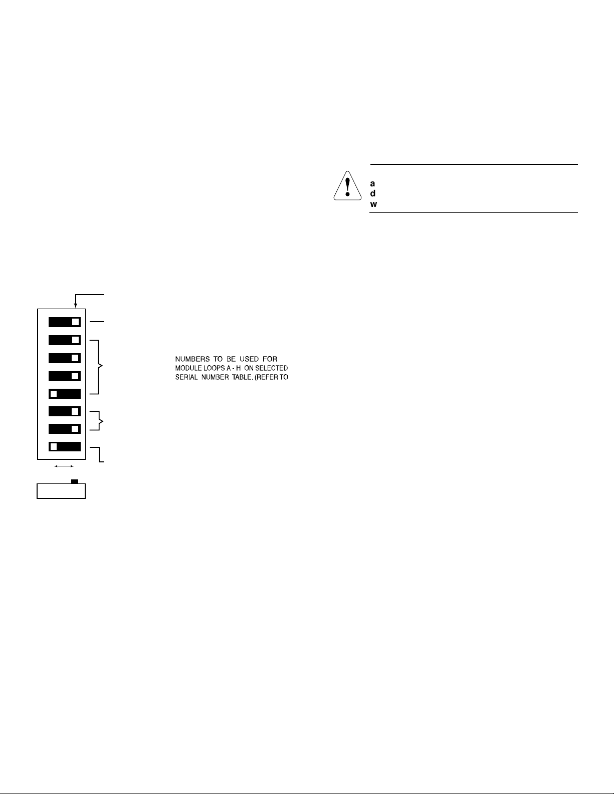
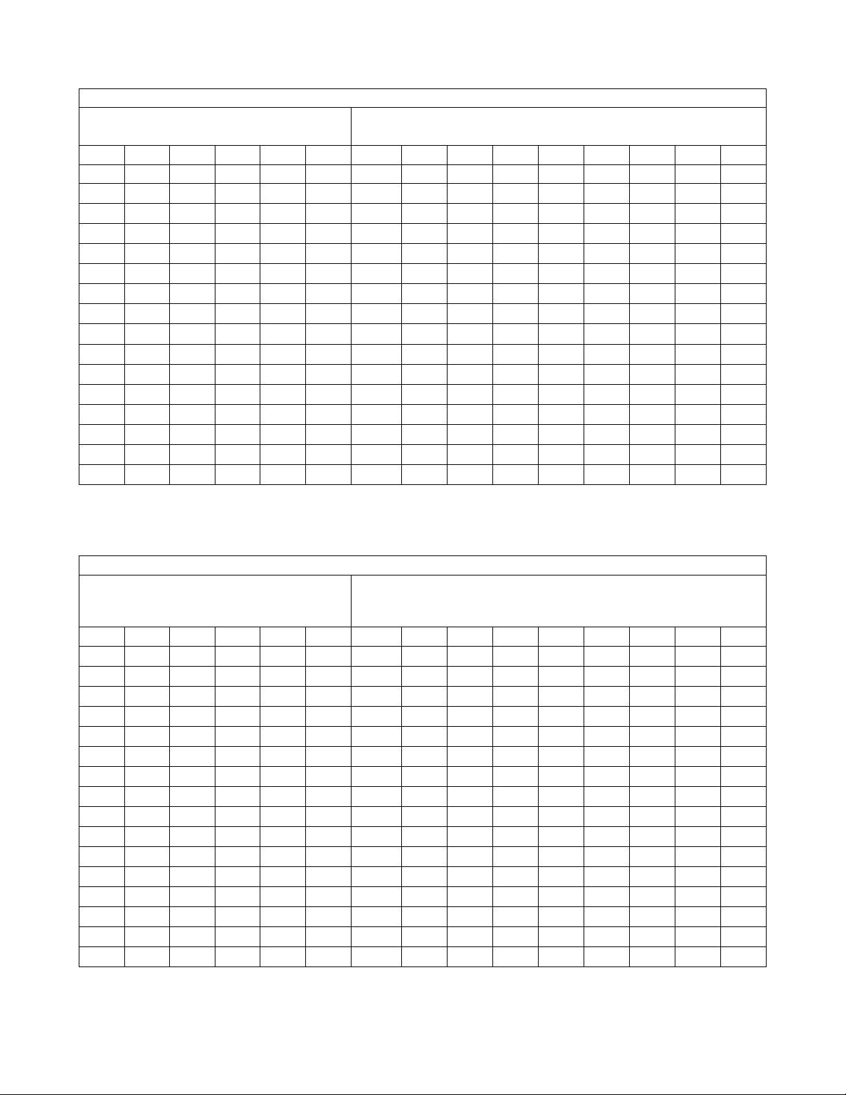
•Each zone is identified by a unique serial number, which is
assigned via on-board DIP Switches.
•Detects faults on all zones within 400ms of occurrence. Loops A
& B can be programmed for fast (10ms) response.
•Provides cover tamper protection, which may be enabled or
disabled via on-board DIP Switches.
MOUNTING
!
1. Power should be disconnected before
proceeding.
2. Be sure to mount the 4208SN before making any
wire connections.
When mounted remotely, tamper protection is required. Holes on the
back of the module’s housing permit it to be mounted horizontally or
vertically. Wires can exit from the side or the breakout on the back of
the housing. To enable tamper protection, set DIP Switch 8 to OFF
and attach the tamper magnet (provided) (Figure 1) to the module
inside cover. Be sure to enable the expansion zone tamper option at
the control (program field *24 = 0). If the module’s cover is removed,
the magnet attached to the cover (positioned near the reed switch) will
cause a tamper signal to be sent to the control for every active zone on
the 4208SN module. When the installation is complete, install the
cover and affix the Serial Number and Zone Assignment Tables to the
inside cover of the control.
When mounted inside the cabinet with the control, the 4208SN should
be mounted horizontally and does not need tamper protection,
provided the cabinet is supervised. Insert two screws into the raised
metal tabs leaving the heads app. 1/8” exposed, then hang the
4208SN using the two slots on the back.
1. INSERT BOTTOM TABS FIRST.
2. ENGAGE TOP WITH CLIP. 4219-002-V0
Figure 1. Tamper Magnet Installation
WIRING
CE
For CE installations, ADEMCO N6361 EMI
suppression bead is required. Refer to the N6361
installation guide for wire routing instructions.
Polling loop and protection loop wires can be brought in either through
the back or front of the unit by removing the knockouts. Use 22 gauge
twisted pair wire for polling loop connections. All protection loops use
10k EOL resistors (included). A maximum resistance of 300 ohms is
allowed on protection loops (excluding EOLR). See Figure 2 for all
connections. Keep in mind that connections to the polling loop are
always required, while aux. power connections are optional.
UL
For UL commercial and household fire installations,
no more than one wire per terminal may be
connected.
4208SN-SOC-V1
NOTES:
4208SN
NOT
USED
( ) GR OUND
(+) 12V
( )
(+)
1
2
3
5
4
4 65
TB2
TB1
REED (TAMPER) SWITCH
10k 10k
LOOPS: A B C D E F G H
(EACH LOOP'S MAX
RESISTANCE:
300 ohms + 10k EOLR)
ON
DIP Switches
1 3
2 10 12
11
7 9
8
10k 10k 10k 10k10k 10k
8
12345 6 7
TO POLLING LOOP
(USE TWISTED P AIR)
IF USING AUXILIARY POWER ON COMMECRICAL
FIRE/BURG COMBINATION SYSTEMS
(e.g.VISTA-128FBP), DO NOT CONNECT THE
POLLING LOOP GROUND ON TERMINAL 2.
AUXILIARY POWER CAN ONLY BE USED IN
BURGLARY APPLICATIONS.
FOR CE INSTALLATIONS A N6363 EMI
SUPPRESSION BEAD IS REQUIRED.
OPTIONAL AUX.
POWER INPUT.
SEE NOTE 1.
1.
2.
Figure 2. Wiring Diagram
UL
1. For dry, indoor use only.
2. Do not install in air-handling spaces.
3. All circuits are supervised and power-limited.
4. Use only 14-22 AWG wire.
5. Refer to the control panel installation
instructions for specific programming /
installation requirements.
UL
For all fire (NFPA) and UL Commercial Burglary
installations, the 4208SN must be tamper protected
or mounted in a tamper-protected cabinet.
This device is NFPA
-
72 Compliant.

DIP SWITCH SETTINGS
The DIP Switches are used to assign serial numbers to loops A
through H. You can assign the serial number of any module loop to
any of the control panel’s expansion zones. You do not lose zone
numbers if you do not use all eight module loops. To select serial
numbers for loops A through H, follow the steps below using Figure 3
and Tables 1 through 4 for DIP Switch settings:
1.
Select fast/slow response for loops A and B using DIP Switch 1:
Fast = OFF (10msec) Slow = ON (400msec). Do not select fast
response for a zone dedicated for Fire usage.
2.
Select Serial Number Assignment Table containing the desired
group of 8 serial numbers (Tables 1 through 4) using DIP switches
6 and 7.
3.
Select the group of 8 serial numbers using DIP switches 2, 3, 4,
and 5. See the Table selected in step 2 for serial number
assignments. If using more than one 4208SN be sure to set each
one to a different group setting.
4.
Select the Tamper Protection setting using DIP Switch 8: Tamper
Disabled = ON Tamper Enabled = OFF. Tamper will report for
every active zone on the 4208SN module.
2 3 4 5 61 7 8
SIDE VIEW
POSITIONS 6-7:
POSITION 8:
OFF ON
SELECT TAMPER PROTECTION
SETTING (SHOWN
OFF = TAMPER ENABLED).
POSITION 1:
DIP SWITCHES (TYPICAL SETTING:
ALL SWITCHES SHIPPED IN "ON" POSITION) .
SELECT RESPONSE TIME FOR
LOOPS A & B.
(SHOWN ON = SLOW: 400msec).
POSITIONS 2-5:
SELECT ROW OF SERIAL
SWITCH POSITIONS 6 & 7 FOR
CORRECT TABLE TO USE.)
SELECT SERIAL NUMBER TABLE
TO BE USED
6 ON, 7 ON = TABLE 1
6 ON, 7 OFF = TABLE 2
4208SN-001-V0
Figure 3. Dip Switch Settings
PANEL PROGRAMMING
When the 4208SN is used as a zone expander, each of the module
loops that will be used must be assigned to one of the control panel’s
expansion zones. To accomplish this, assign a module loop’s serial
number to a control panel’s expansion zone using procedures
contained in the control panel’s installation instructions. Expansion
zones must be programmed as INPUT TYPE “6”−SL (Serial Number
V-Plex Loop Device), which will enable the control panel to accept the
serial number. Module loops can be programmed in any order and can
be assigned to any legitimate control panel expansion zone.
!
If enrolling a serial number by faulting its
associated loop, be sure that other V-Plex
loop
dev
ices are not activated, as they may interfere
with the device being enrolled.
When prompted to “enroll” the serial number for a particular zone, you
may enter the serial number for the associated module loop manually
through the keypad, through the V-Link downloader, or by momentarily
.faulting (shorting) and restoring the terminals of the associated
module loop twice when prompted by the keypad. If entering a serial
number manually through the keypad, enter the serial number and
press “*” to advance to the next prompt, which will ask you for the loop
number. Enter a “1” for the loop number for each serial number
entered.
If enrolling or entering a serial number, and the message “Duplicate of
Zone XX” is displayed, another device with that same serial number is
aready in the system. In that case, use a different serial number group
setting on the 4208SN.
If desired, peel the label corresponding to the serial number
assignment table used from the sheet of labels supplied, and apply it to
the outside of the case cover or next to the module for future
reference.
VERIFICATION OF PROGRAMMING
To verify proper 4208SN wiring and programming, fault each of the
module loops that are used and verify that the control panel displays
the correct zone number on the keypad.
WARRANTY
For the latest warranty information, please go to:www.resideo.com

– 3–
Table 1: 4208SN Serial Number Assignments
THE DIP SWITCH SETTINGS PRESET THE LOOPS TO THE APPLICABLE SERIAL NUMBERS
Dip Switch Settings
(6 &7 ON selects serial numbers in this table)
Loop Serial Number
2 3 4 5 6 7 Prefix A B C D E F G H
ON ON ON ON ON ON 006- 5540 5541 5542 5543 5548 5549 5550 5551
ON ON ON ON ON 019- 6612 6613 6614 6615 6620 6621 6622 6623
ON ON ON ON ON 013- 9268 9269 9270 9271 9276 9277 9278 9279
ON ON ON ON 020- 8900 8901 8902 8903 8908 8909 8910 8911
ON ON ON ON ON 027- 8532 8533 8534 8535 8540 8541 8542 8543
ON ON ON ON 034- 8164 8165 8166 8167 8172 8173 8174 8175
ON ON ON ON 041- 7796 7797 7798 7799 7804 7805 7806 7807
ON ON ON 048- 7428 7429 7430 7431 7436 7437 7438 7439
ON ON ON ON ON 055- 7060 7061 7062 7063 7068 7069 7070 7071
ON ON ON ON 062- 6692 6693 6694 6695 6700 6701 6702 6703
ON ON ON ON 069- 6324 6325 6326 6327 6332 6333 6334 6335
ON ON ON 076- 5956 5957 5958 5959 5964 5965 5966 5967
ON ON ON ON 083- 5588 5589 5590 5591 5596 5597 5598 5599
ON ON ON 090- 5220 5221 5222 5223 5228 5229 5230 5231
ON ON ON 097- 4852 4853 4854 4855 4860 4861 4862 4863
ON ON 104- 4484 4485 4486 4487 4492 4493 4494 4495
Table 2: 4208SN Serial Number Assignments
THE DIP SWITCH SETTINGS PRESET THE LOOPS TO THE APPLICABLE SERIAL NUMBERS
Dip Switch Settings
(6 ON, 7 OFF selects serial numbers in this
table)
Loop Serial Number
2 3 4 5 6 7 Prefix A B C D E F G H
ON ON ON ON ON 006- 5796 5797 5798 5799 5804 5805 5806 5807
ON ON ON ON 019- 6868 6869 6870 6871 6876 6877 6878 6879
ON ON ON ON 013- 9524 9525 9526 9527 9532 9533 9534 9535
ON ON ON 020- 9156 9157 9158 9159 9164 9165 9166 9167
ON ON ON ON 027- 8788 8789 8790 8791 8796 8797 8798 8799
ON ON ON 034- 8420 8421 8422 8423 8428 8429 8430 8431
ON ON ON 041- 8052 8053 8054 8055 8060 8061 8062 8063
ON ON 048- 7684 7685 7686 7687 7692 7693 7694 7695
ON ON ON ON 055- 7316 7317 7318 7319 7324 7325 7326 7327
ON ON ON 062- 6948 6949 6950 6951 6956 6957 6958 6959
ON ON ON 069- 6580 6581 6582 6583 6588 6589 6590 6591
ON ON 076- 6212 6213 6214 6215 6220 6221 6222 6223
ON ON ON 083- 5844 5845 5846 5847 5852 5853 5854 5855
ON ON 090- 5476 5477 5478 5479 5484 5485 5486 5487
ON ON 097- 5108 5109 5110 5111 5116 5117 5118 5119
ON 104- 4740 4741 4742 4743 4748 4749 4750 4751

SPECIFICATIONS
Physical:
Width:
6-7/16” (163mm)
Height:
4
-
1/4” (108mm)
Depth:
1
-
1/4” (32mm)
Electrical:
Current: 33.6mA when polling loop provides power to module;
0.6mA when using external power. See Table 5.
Polling
Loop Voltage:
11V nominal; 8
-
11
VDC
range
Power Input (optional): 12VDC @ 33mA (from control
panel’s auxiliary power)
Exp
ander Sensor Loop Response:
Slow:
400msec (all loops)
Fast:
10msec (option for loops A and B)
Note: These currents apply when polling loop input = 11VDC
and 12VDC input is not connected to external
supply.
Sensor Loop Max. Resistance:
Up to 300 ohms of wire
resistance + 10k EOLR.
SEE THE CONTROL PANEL’S INSTALLATION INSTRUCTIONS FOR COMPLETE INFORMATION REGARDING LIMITATIONS OF THE
ENTIRE SECURITY SYSTEM.
Table 5. Current Draw Calculations
Power Input Source (8 – 11VDC)Current Draw (all zones shorted)
From Polling Loop From Control Panel Aux. Power
Polling Loop Only 33.6mA N/A
Polling Loop and External Power Input
0.6mA 33mA
UL
Do not use a remote power supply. On commercial fire panels, when using optional aux. power
and ground from the control, do not additionally connect the polling loop ground to this device.
For UL Listed Commercial Fire Usage:
Use N.O. contacts. Style B, supervise these loops using Model
# EOL 100 fire listed 10k EOLRs (purchased separately).
For UL Listed Commercial Burglary Usage:
Use N.O. or N.C. contacts. Supervise using EOLRs supplied
.
FEDERAL COMMUNICATIONS COMMISSION (FCC) STATEMENTS
The user shall not make any changes or modifications to the equipment unless authorized by the Installation Instructions or User's Manual.
Unauthorized changes or modifications could void the user's authority to operate the equipment.
CLASS B DIGITAL DEVICE STATEMENT
NOTE: This equipment has been tested and found to comply with the limits for a Class B digital device, pursuant to part 15 of the FCC Rules.
These limits are designed to provide reasonable protection against harmful interference in a residential installation. This equipment generates, uses
and can radiate radio frequency energy and, if not installed and used in accordance with the instructions, may cause harmful interference to radio
communications. However, there is no guarantee that interference will not occur in a particular installation. If this equipment does cause harmful
interference to radio or television reception, which can be determined by turning the equipment off and on, the user is encouraged to try to correct
the interference by one or more of the following measures:
•Reorient or relocate the receiving antenna.
•Increase the separation between the equipment and receiver.
•Connect the equipment into an outlet on a circuit different from that to which the receiver is connected.
•Consult the dealer or an experienced radio/TV technician for help.
INDUSTRY CANADA (IC) STATEMENTS
This device complies with RSS210 of Industry Canada. Operation is subject to the following two conditions: (1) This device may not cause harmful
interference, and (2) This device must accept any interference received, including interference that may cause undesired operation.
This Class B digital apparatus complies with Canadian ICES-003.
Cet appareil numérique de la classe B est conforme à la norme NMB-003 du Canada.
Responsible Party / Issuer of Supplier’s Declaration of Conformity: Ademco Inc., a subsidiary of Resideo Technologies, Inc., 2 Corporate Center Drive., Melville, NY
11747, Ph: 516-577-2000.
The product should not be disposed of with other household waste. Check for the nearest authorized collection centers or authorized recyclers. The correct disposal of
end-of-life equipment will help prevent potential negative consequences for the environment and human health.
Any attempt to reverse-engineer this device by decoding proprietary protocols, de-compiling firmware, or any similar actions is strictly prohibited.
This product manufactured by Resideo Technologies, Inc. and its affiliates
K0797V2C 3/09 Rev. C
2 Corporate Center Drive, Suite 100
P.O. Box 9040, Melville, NY 11747
2020 Resideo Technologies, Inc.
www.resideo.com
UL Listings:
Commercial Fire: UL864
Household Burg: UL1023
Household Fire: UL985
Commercial Burg: UL365, UL609, UL1076, UL1610
Other resideo Extender manuals
Popular Extender manuals by other brands

Rose electronics
Rose electronics CrystalView USB2 Installation and operation manual

NORAUTO
NORAUTO START PLUS 2223450 instruction manual

hager
hager REH311X quick start guide

Abtus
Abtus CAT-HD14TA-G User's operation guide

Aurora Multimedia
Aurora Multimedia ASP-FIBRS2 user manual

DVIGear
DVIGear DVI-7317-TX quick start guide