resideo Braukmann CBU145 User manual

Instructions
Braukmann
CBU145
Compact Booster Unit - double pump
To ensure the quality of potable water according to EN1717
32303722-001

EN
Resideo Technologies
2
Translation of original - EN1H-1375GE23 R1020
Contents
1. Safety Guidelines............................................................................ 3
1.1 Safety instructions in this manual ...................................................... 3
1.2 Safety instructions in the system ....................................................... 3
1.3 General safety instructions................................................................ 3
1.4 Further safety regulations.................................................................. 3
1.5 Unauthorised operation types............................................................ 3
1.6 Residual dangers in handling the compact booster unit...................... 3
1.6.1 Mechanical residual dangers.................................................... 3
1.6.2 Residual dangers pertaining to fluids........................................ 4
1.6.3 Residual electrical hazards ...................................................... 4
1.6.4 Thermal hazards...................................................................... 4
1.6.5 Residual biological hazards...................................................... 4
1.6.6 Residual chemical hazards ...................................................... 4
1.6.7 Consequences and dangers that result from not observing the
manual.................................................................................... 4
1.7 Basic Safety Measures ..................................................................... 5
1.7.1 Keep information available....................................................... 5
1.7.2 For environmental protection.................................................... 5
1.7.3 Modifications to the compact booster unit ................................. 5
1.8 Duty of due care of the operator ........................................................ 5
1.9 Safety instructions for the operator/operating personnel ..................... 5
1.10Safety instructions for maintenance, inspections andassembly work .. 5
1.11Requirements for operating personnel............................................... 5
1.11.1Operating personnel................................................................ 5
1.12Personal safety equipment................................................................ 5
2. General information........................................................................ 6
2.1 Conformity with the following norms .................................................. 6
2.1.1 Warranty and liability ............................................................... 6
2.1.2 Storage and perfect condition................................................... 6
2.1.3 Illustrations.............................................................................. 6
2.1.4 Symbols.................................................................................. 6
2.2 Other applicable documents.............................................................. 6
2.3 Glossary........................................................................................... 6
3. Description...................................................................................... 7
3.1 Intended use..................................................................................... 7
3.2 Non-intended use ............................................................................. 7
3.3 Version............................................................................................. 7
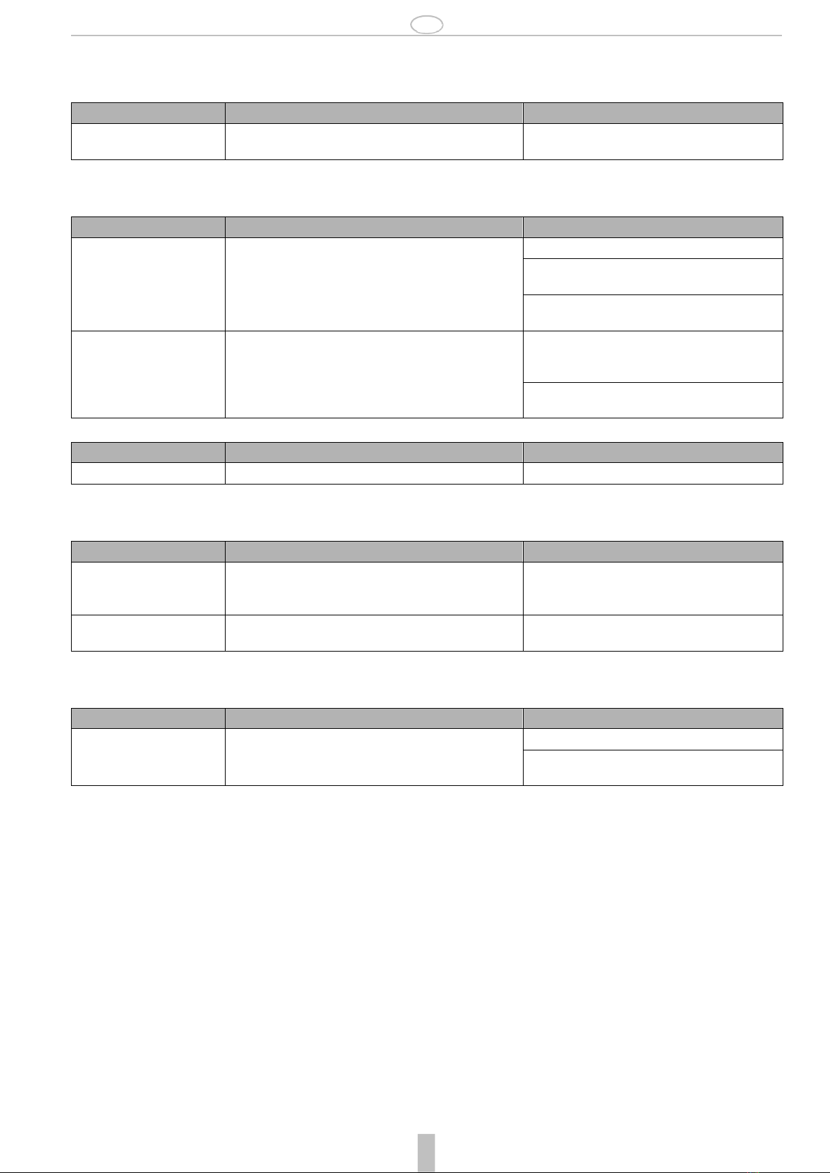
3.3.1 Structure ................................................................................. 7
3.4 Function ........................................................................................... 8
3.4.1 Installation type ....................................................................... 8
3.4.2 Inlet side ................................................................................. 8
3.4.3 Outlet side............................................................................... 8
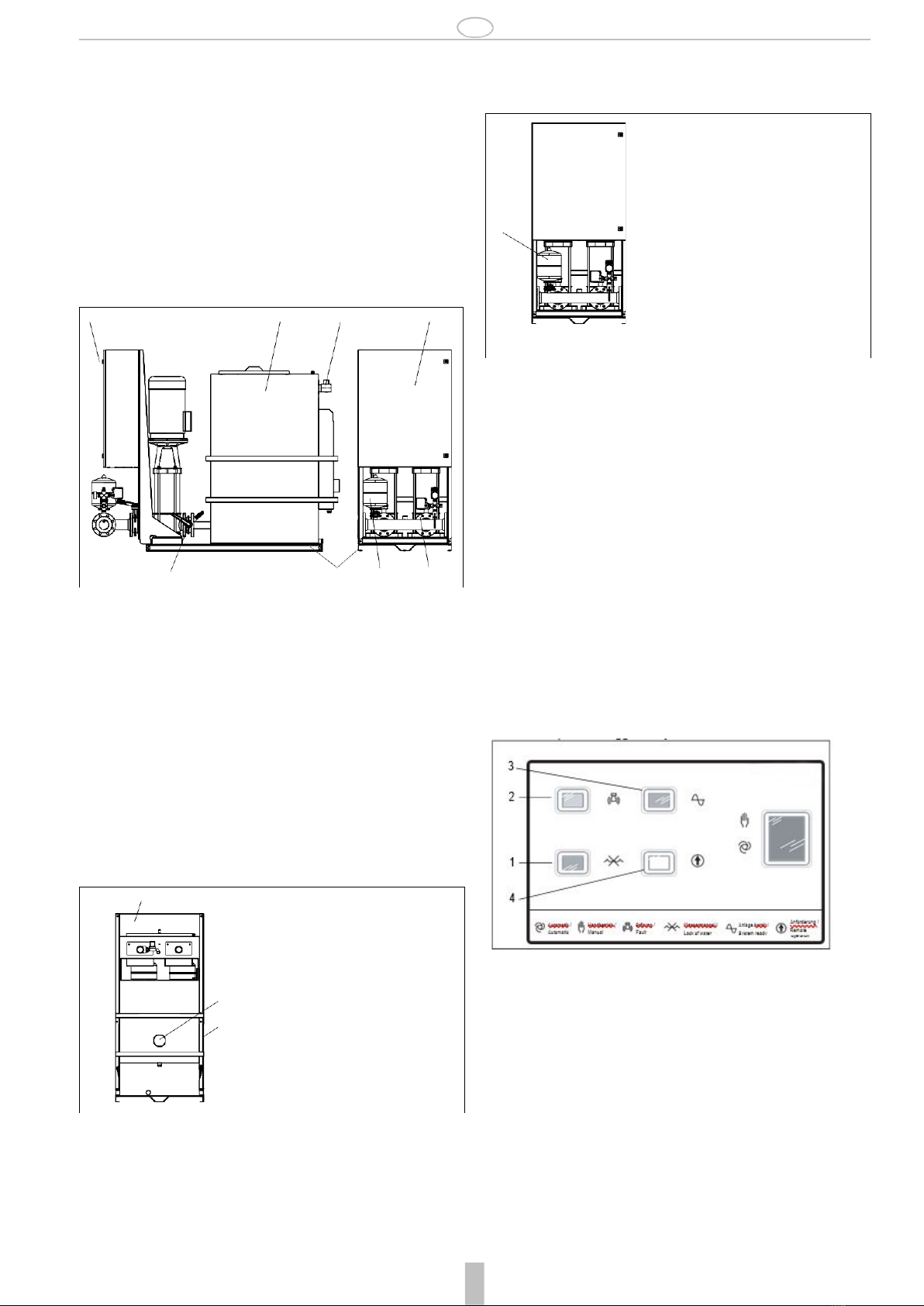
3.4.4 Switch cabinet ......................................................................... 8
3.5 Mode of operation............................................................................. 9
3.5.1 Mode of automatic operation.................................................... 9
3.5.2 Mode of manual operation ....................................................... 9
3.5.3 Mode of operation for testing.................................................... 9
3.5.4 Mode of operation for protection against dry running................. 9
3.5.5 Mode of operation for temperature monitoring........................... 9
3.5.6 Mode of operation for refilling................................................... 9
3.5.7 Mode of operation for flushing.................................................. 9
3.5.8 Mode of operation for separation of potable water..................... 9
3.5.9 Mode of operation in the event of power loss ............................ 9
3.6 Options............................................................................................. 9
4. Technical data................................................................................10
4.1 Construction dimensions..................................................................11
4.2 Noise expectancy values..................................................................11
4.3 Authorised environmental conditions ................................................11
5. Shipping.........................................................................................12
5.1 Check condition upon delivery..........................................................12
5.2 Transportation .................................................................................12
6.
Assembly.......................................................................................12
6.1 General safety instructions...............................................................12
6.2 Installation according toDIN 14462 ..................................................12
6.3 Installation according toDIN 1988....................................................12
6.4 Inspection before assembly..............................................................13
6.4.1 Installation site .......................................................................13
6.5 Installing the compact booster unit....................................................13
6.6 Installing the pipelines......................................................................13
6.6.1 Connecting the overflow .........................................................13
6.6.2 Installing the compensator (optional).......................................13
6.7 Buffer tank.......................................................................................13
6.8 Protection against dry running..........................................................13
6.9 Installing valves...............................................................................13
6.10Electrical connection........................................................................13
6.10.1Safety instructions..................................................................14
6.10.2Connection specifications.......................................................14
6.10.3Connecting electrical accessories...........................................14
6.10.4Connecting the limit switch .....................................................14
6.10.5Potential-free contacts............................................................14
6.11Standby indicator.............................................................................15
7. Start-up..........................................................................................15
7.1 Safety instructions for start-up..........................................................15
7.2 Start-up requirements ......................................................................15
7.3 Initial operation................................................................................15
7.3.1 Settings .................................................................................16
7.4 Switching the system on ..................................................................16
7.5 Start-up checklist.............................................................................16
8. Maintenance ..................................................................................17
8.1 Safety instructions for maintenance..................................................17
8.2 Inspection .......................................................................................17
8.2.1 Buffer tank .............................................................................17
8.2.2 Monitoring Operation..............................................................18
8.2.3 Mode of operation in the event ofpower loss...........................18
8.2.4 Checklist for Inspection...........................................................18
8.3 Maintenance ...................................................................................19
8.3.1 Setting the precharge pressure for the membrane pressure
vessel....................................................................................19
8.3.2 Cleaning the dirt trap ..............................................................19
8.3.3 Checklist for maintenance work...............................................19
9. Troubleshooting............................................................................19
9.1 Possible malfunctions / Errors..........................................................19
9.2 Possible causes / Elimination...........................................................20
10. Shut-down, restart.........................................................................21
10.1Shutting down the compact booster unit ...........................................21
10.2Restarting the compact booster unit .................................................21
11. Storage ..........................................................................................21
11.1Short-term storage...........................................................................21
11.2Storage/Preservation.......................................................................21
11.3Storage conditions
...........................................................................21
12. Disassembly, disposal ..................................................................21
12.1Safety instructions for disassembly...................................................21
13. Spare parts ....................................................................................22
13.1Parts index CBU145........................................................................22
14. Start-up protocol ...........................................................................23
15. Declaration of no objection ...........................................................24
16. Proof of Maintenance ....................................................................25

EN
EN1H-1375GE23 R1020 - Translation of original
3
Resideo Technologies
1. Safety Guidelines
1.1
Safety instructions in this manual
Danger
Places with this sign signify that death, severebodily injury orsignificant
property damage will occur if the appropriate precautionary measures
are not followed!
Warning
Places with this sign signify that death, severebodily injury orsignificant
property damage may occur if the appropriate precautionary measures
are not followed!
Caution
Places with this sign signify that small bodily injury or slight property da-
mage may occur if the appropriate precautionary measures are not fol-
lowed!
Places with this sign provide technical information and tips on usage
that damage to the machine must be avoided.This symbol is not a safe-
ty indication.
Places with this sign provide information about possible hazards to the
environment
Please notice that a safety symbol never can replace the text of the
safety instruction itself - the text of the safety instruction must be read
entirely!
1.2
Safety instructions in the system
Danger of burning on hot surfaces of pump housing
1.3
General safety instructions
This manual contains basic instructions which are to be observed in trans-
port, assembly, start-up, operation, maintenance, shut-down, storage and
waste disposal.
The following safety instructions have to be observed while operating the
compact booster unit:
•When using the compact booster unit, the data, operation and usage
conditions specifically authorised in the technical data sheet and the
operating manual have to be observed.
•Never exceed the permissible limits pertaining to pressure, temperature,
etc. as stated in the documentation.
•Observe all safety instructions as well as the operating instructions of the
manual.
•Instructions that are directly attached to the system have to be observed
and must be kept completely legible. This applies for exampleto:
-Safety instructions
-Arrow for rotation direction
-Connection labels
-Type label
•Before assembly and start-up, the manual has to be read by the operator
as well as by the responsible technical/operating personnel and has to be
stored at the site of the compact booster unit at alltimes.
•Installation and maintenance work may only be performed by authorised
specialist personnel with the appropriate tools.
•The technical condition of the compact booster unit has to be checked
regularly (at least once a year) by the operating company.
•The local safety and accident regulations have to be observed when
operating the compact booster unit.
•The general technical rules must be observed when planning the usage
and operating the device.
•Modification of the compact booster unit is not permitted and leads to the
loss of warranty.
•Afteran interruption of the electrical or fluid supply, a defined or controlled
re-run of the process must be ensured.
•The operator is responsible for complying with local regulations that are
not covered by the manual.
1.4
Further safety regulations
Besides the safety instructions presented in this manual and its intended
use, the following safety regulations are valid:
•Accident prevention regulations, safety and operating regulations
•Safety regulations for handling hazardous substances
•Applicable standards and laws
1.5
Unauthorised operation types
The limits that are stated in the documentation have to always be complied
with. The delivered system is only guaranteed to operate reliably when it is
used as intended.
1.6
Residual dangers in handling the compact booster unit
Danger and adverse effects may result from use of the compact booster unit
•for the body and life of the operator or third person
•for the compact booster unit itself
•to other property.
The basis for safe and error-free operation of the compact booster unit is
knowledge of the instructions for safety and operation in this manual.
1.6.1
Mechanical residual dangers
During normal operation, no danger is threatened from mechanical compon-
ents.

EN
Resideo Technologies
4
Translation of original - EN1H-1375GE23 R1020
1.6.2
Residual dangers pertaining to fluids
During normal operation, no danger is threatened by hydraulic components.
Hazards might result solely under the following conditions.
Danger area
Type of hazard
Reduction of hazard
Pipelines
Injury through high pressure
Clear pipelines of pressure and medium prior to assem-
bly, maintenance, shut-down!
1.6.3
Residual electrical hazards
During normal operation, no danger results from the electrical equipment of the compact booster unit.
Hazards might result solely under the following conditions.
Danger area
Type of hazard
Reduction of hazard
Injury from cables
Danger to life !
Electric shock of 230/400V from electric voltage
Connect up protective earth system!
Always switch off power supply and secure against swit-
ching on again during maintenance and servicing work!
Comply with the valid accident prevention and safety re-
gulations for electrical devices!
Electrostatically endangered
components / subassemblies
The device contains electronic componental elements that react
sensitively to electrostatic discharge (ESD). Contact with electro-
statically charged persons or objects endangers these compo-
nental elements. Worst case scenario: they will be immediately
destroyed or fail after start-up.
Comply with requirements according to EN 100 015 - 1,
in order to minimise or avoid damage through shock-
type
electrostatic discharge!
Do not touch electronic componental elements when the
power supply is on!
1.6.4
Thermal hazards
Danger area
Type of hazard
Reduction of hazard
Hot surfaces of the pump housing
Contact can cause burning
Wear personal safety equipment!
1.6.5
Residual biological hazards
During normal operation, no biological danger results from the compact booster unit.
Hazards might result solely under the following conditions.
Danger area
Type of hazard
Reduction of hazard
Buffer tank
Danger of microbial contamination
Set the automatic rinsing device according to local condi-
tions!
Clean the buffer tank regularly!
Inlet lines from the potable water
network
Danger of contamination caused by stagnant water
Make sure the inlet lines from the potable water network
are equipped with a rinsing device!
1.6.6
Residual chemical hazards
During normal operation, no chemical danger results from the compact booster unit.
Hazards might result solely under the following conditions.
Danger area
Type of hazard
Reduction of hazard
Use of detergents
Danger through contact with or breathing in dangerous fluids, ga-
ses, fumes, vapours or dust
Wear personal safety equipment!
Pay attention to the safety specifications sheet of deter-
gent manufacturers!
1.6.7
Consequences and dangers that result from not observing themanual
•Not observing this manual will lead to loss of the warranty and make damage claims invalid.
•Failure to observe the manual can lead, for example, to the following dangers:
-Hazard to persons caused by electrical, thermal, mechanical, and chemical influences
-Loss of important product functions
-Failure to perform required maintenance and service measures
-Environmental hazard caused by leakage of hazardous substances

EN
EN1H-1375GE23 R1020 - Translation of original
5
Resideo Technologies
1.7
Basic Safety Measures
1.7.1
Keep information available
This manual has to be stored. It has to be ensured that all persons who
operate the compact booster unit have access to the manual at all times.
1.7.2
For environmental protection
When operating or servicing the compact booster unit, the regulations
concerning waste avoidance and the proper recycling or disposal of wa-
ste must be observed.
Particular attention must be paid that materials and agents dangerous
to the groundwater such as fats, oils, coolants, solvent-based liquid de-
tergents, etc. do not pollute the ground or access the sewage system.
These materials must be caught in suitable tanks, stored, transported
and properly disposed of.
1.7.3
Modifications to the compact booster unit
When using externally procured parts, there is no guarantee that these are
designed and constructed to tolerate demands made upon them or whether
they comply with safety regulations.
For safety reasons, no unauthorised modifications may be made to the
compact booster unit.
Parts and special equipment not delivered by Resideo are also not autho-
rised by Resideo for use.
1.8
Duty of due care of the operator
This compact booster unit was designed and constructed according to a risk
assessment and after careful selection of the harmonised standards that
apply, as well as according to further technical specifications. It thus
complies with best practice and guarantees the highest safety standard.
This level of safety can only be attained during operational practice if all
required safety measures have been taken. It is the duty of care of the
operator of the compact booster unit to plan these measures and enforce
their implementation.
In particular, the operator must ensure that
•the compact booster unit is only operated as intended
•the compact booster unit is only operated in perfect workingcondition.
•the required personal safety gear for operating, maintenance and repair
personnel is available and is used
•the manual has to be kept legible at all times and stored on-site with the
compact booster unit.
•the compact booster unit is assembled, commissioned, operated, main-
tained, and shut down solely by sufficiently qualified and authorised
personnel.
•this personnel is regularly instructed on all relevant questions of work
safety and environmental protection, and has also read and understood
the manual and particularly the safety instructions itcontains.
•none of the safety and warning signs attached to the compact booster unit
are removed and all remain legible.
•a hazard assessment (according to the Safety at Work Act § 5) is
conducted to detect further hazards that may arise from the particular
working conditions on-site where the compact booster unit is operated.
•all further information and safety instructions which arise from the hazard
assessment process shall be summarised in operating instructions
(according to the work equipment regulation § 6).
•measures for the decontamination of systems that pump hazardous
medium are stated in the operating manual
•the drain output lines are sufficiently dimensioned
1.9
Safety instructions for the operator/operating personnel
•Provide on-site protection against contact for hot,cold, and moving parts
and check if they function properly.
•Do not remove the protection against contact during operation of the
pump.
•Eliminate hazards caused by electrical energy (for details refer to the
country specific regulations and/or local power supplycompanies).
1.10
Safety instructions for maintenance, inspections and
assembly work
•Alterations or modifications of the system are only permitted with the
consent of the manufacturer.
•Use only original parts or parts authorised by the manufacturer.
•Use of parts other than those authorised may lead to loss of liability for
any damage they may cause.
•Perform service on the system only when the machine is off.
•The pump housing has to be at ambient temperature.
•The pump housing has to be depressurised and empty.
•The procedures described in the manual for shutting down the system
have to be observed under all circumstances.
•Decontaminate systems that pump hazardous medium.
•Reinstall safety equipment and protective devices and activate them
again immediately after work on the system has been completed. Before
starting up again, observe the start-up checklist.
•Keep unauthorised persons (e.g. children) away from the system.
1.11
Requirements for operating personnel
1.11.1
Operating personnel
This compact booster system may only be asembled, started, operated,
maintained, and shut down by persons who have been trained, instructed
and authorised to do so.
In some cases, training can be arranged by the manufacturer if asked by the
operator.
Training or personnel to operate system may only be conducted under the
supervision of specialised technicians.
The relevant authorisations of the personnel are to be specified by the
operating company in the form of an operating instruction.
Over and above this, special qualifications are required for the following
tasks:
•Only electricians may perform work on electrical equipment.
•Assembly, maintenance, servicing and repair work may only be
performed by qualified, specialist personnel
The basic regulations on work safety and accident prevention are to be
observed.
1.11.1.1 Qualified personnel
Qualified personnel are persons who on account of their training, experience
and instruction also their knowledge of the relevant norms, regulations, acci-
dent prevention regulations and operating conditions, including those
persons responsible for the safety of the system, have been authorised to
perform the relevant and required tasks, meanwhile being able to recognise
and avoid dangers. This includes required knowledge of First Aid measures
and the local ambulance services and facilities.
1.12
Personal safety equipment
No personal safety equipment is required to operate the compact booster
unit.

EN
Resideo Technologies
6
Translation of original - EN1H-1375GE23 R1020
2. General information
The manual is a part of the series and the versions as mentioned on the title
page. The manual describes the safe and proper use in all modes of opera-
tion.
The type label indicates the series and size, the most important operating
data and the order number. The factory number/serial number describes the
identifies the system uniquely and serves this purpose for all further busi-
ness transactions.
In order to maintain the warranty, in the event of damage immediately
contact the nearest Resideo service centre.
2.1
Conformity with the following norms
Pump unit: Machinery Directive 2006/42/EG
Pump unit: EMC Directive 2004/108/EG
2.1.1
Warranty and liability
As a matter of principle, the general sales and delivery terms of the Honey-
well Company apply. Warranty and liability claims for injury to persons and
damage to property are ruled out if they arise from one or more of the follo-
wing causes.
•Non-intended use of the compact booster unit
•Improper assembly, start-up, operation and maintenance of the compact
booster unit
•Failure to comply with the instructions in the manual concerning transport,
storage, assembly, start-up, operation, maintenance, and service of the
compact booster unit
•Unauthorised constructional modifications of the compact boosterunit
•Negligent monitoring of components subject to stress
•Improperly performed repairs
•Catastrophes through effect of a foreign object or force majeure
2.1.2
Storage and perfect condition
This instruction manual is a part of the compact booster unit and has to be
complete and accessible at all times. Any instruction or page that is missing
has to be replaced immediately.
2.1.3
Illustrations
The illustrations used are examples of one possible version of the compact
booster unit and might differ in individual cases from the actual compact
booster unit version.
2.1.4
Symbols
1. Start of a task description
2. Next work step
- Result of an action
•List of several options
Reference to other documents
2.2
Other applicable documents
Data sheet CBU145
Operating instructions of the operating company
Data sheets
Documentation fortheswitch cabinet/circuit diagram
Wiringschemefor the external remote on/off control
Instructions for the pump
Instructions for the pressure switch
Instructions for the throttle valve
Instructions for the membrane pressure vessel
Instructions for the check valves
Instructions for magnetic valves
Declaration of Conformity
2.3
Glossary
Pump requirements
Pump actuation means that a pump starts up when a start signal is sent by a
pressure switch, from a wall hydrant (limit switch), by remote on/off, or from
the wire breakage and short circuit monitoring relays.
Automatic operating mode
The pump is switched on and off either by pressure control or by a contact
on the wall hydrant.
EN 1717
European standard that specifies technical regulations for potable water
installations.
DIN 14462
German standard that pertains to extinguishing water equipment and with
which fire extinguisher systems have to comply.
Membrane pressure vessel
The membrane pressure vessel is for compensating pressure drops in the
pipeline network behind the compact booster unit, that can occur because of
loss of minimal quantities.
That minimises the frequency of operation of the compact booster.
Noise expectancy values
The expected noise emission, stated here as sound pressure level (SPL) in
dB(A).
Manual operation
During manual operation, the compact booster unit is connected directly to
the mains and independent of the control unit.
Certificate of no objection
A certificate of no objection is a declaration that the system has been
cleaned properly so that parts that have been in contact with medium are not
dangerous for health and environment.
Danger source
Consequence of non-compliance
Avoidance
Pictogram Danger classification

EN
EN1H-1375GE23 R1020 - Translation of original
7
Resideo Technologies
3. Description
Resideo Compact Booster Unit - double pump CBU145 as a safety device to
separate potable water from category 5 fluids according to DIN EN 1717 for
fire extinguisher applications according to DIN 14462 and DIN1988-600 with
free outlet type AB and vertical high-pressure pumps.
Fully automatic, fully wired Compact Booster Unit-double pump with modular
design comprising a double pump system with redundant operation and a
buffer tank for the hygienic separation of potable water and category 5 fluids
according to DIN EN 1717, on a common base frame. The modular design
makes it possible to disconnect modules for installation in buildings with
limited space. The system is switched on and off regulated bypressure.
Separation of systems as a means to protect potable water from being
contaminated by fluids of the category 5 according to EN 1717
Pump medium Non-potable water
Without aggressive, abrasive and solid
components
Flow rate max. 48 m3/h (13,3 l/s)
Pumping head up to 125 m
Medium temperature up to 30 °C
Ambient temperature up to 40 °C
Pressure rating PN16
Inlet pressure
3.3
Version
The Compact Buster Unit comprises the following modules, that can be
disassembled (for example for transport purposes).
•The double pump booster unit has two pumps, a control unit, valves and
connected piping. The pressure switch and temperature sensor are
installed, wired and preset with standard default values in thefactory.
•Buffer tank with inlet and flushing apparatus as well as level, overflow and
dry running monitor. The components are assembled and preset in the
factory. The electrical components are connected to the control unit of the
booster station with plug connections. Thus if required an electric separa-
tion can be made.
•A common base frame for the double pump booster unit and the supply
container that allows tranportation with a standard pallet hand forklift.The
pumps and base frame are equipped with vibration dampers.
3.3.1
Structure
Double pump system with redundant operation, including back-up pump
unit, made up of:
•two normal sucking, vertical high-pressure rotary pumps with all compon-
ents in contact with the medium made of stainless steel
•Standard-motor each pump, energy efficiency class IE2
•Check valves for each pump
•Shut-off valves on the inlet and outlet sides of each pump
•Diaphragm expansion vessel on the outlet side as vessel
•Vibration damper for each pump
up to 18 m3/h
up to 36 m3/h
up to 48 m3/h
min. 1,5 bar, max. 8 bar
min. 3 bar, max. 8 bar
min. 4 bar, max. 8 bar
•Pressure gauge display
•Isolation valves, lockable
•Pump protection through temperature related minimum flow
Supply voltage 2 x 3/N/PE, AC 400 V, 50 Hz
3.1
Intended use
The compact booster unit may only be operated in such areas as described
in the other applicable documents.
Non-intended operation of the compact booster unit can result in danger to
persons, systems, the surroundings and the environment.
•Operate the compact booster unit only if it is in perfect working condition.
•Do not operate the compact booster unit if it is only partially assembled.
•The compact booster unit may only be used to pump the medium as
described in the documentation of the respective version.
•Never operate the compact booster unit without pump medium.
•Observe the values for minimum pumping rates (avoiding damage
because of overheating, storage damage, ...).
•Observe the values for maximum pumping rates (to avoid damage due to
overheating, floating ring seal damage, cavitation damage, storage
damage, ...).
•Do not throttle the input of the compact booster unit (to avoid cavitation
damage).
•Other modes of operations, if not mentioned in the documentation, have
to be coordinated with the manufacturer.
3.2
Non-intended use
The compact booster unit is not designed for operation outside. Tempera-
ture, light and moisture can lead to malfunctions and damaging devices.
•Do not operate the compact booster unit outside.
•Operate the compact booster unit only as intended.
•Do not fill aggressive or flammable medium into the medium lines of the
system.
•No mechanical stress on housings (e.g. by depositing objects or as a
step).
•Do not perform any external modifications on the device housing. Do not
paint housing parts and screws!
•Do not disassemble the compact booster unit more than is necessary for
purposes of installation and maintenance.
•Piping made of chrom-nickel-steel alloy
•The system is connected to the installation pipeline with circularflanges
•Base frame made of coated steel
Two complete, electrically independant electrical
switching apparatus each with an electro-mechanical control unit
comprising:
•Power supply via 3/N/PE, 400V AC, 50Hz
•Main switch that is protected against unauthorised operation
•Control transformer 400V / 230V- 24V
•Green indicator light for standby
•Red indicator light for water shortage
•Yellow indicator light for malfunction
•White indicator light for operation on demand
•Manual/automatic switch
•Timer for 24 hour functional operation and weekly flushing cycle
•Remote on/off, protected against wire breakage and short circuit
•Phase monitor relays with rotation monitoring and phase failure protection
•Smooth operated start-up
•Motor protection device, in case of failure only indicates an alarm
•Terminal strip with markings for all connections
•Plug connectors for easy connection of electrical equipment on the buffer
tank
Terminal strip for potential-free contact for time-delayed potable water
separation (adjustable)
•Control voltage 230V, AC 6A
Buffer tank made of polyethylene with:
•Non-circular, free overflow according to EN 13077, Type AB
•Drainage connection DN 100 (nozzles) with integrated siphon trap
•Usable volume 540 litres
•Refilling of potable water via float valve
•Automatic flushing device via solenoid valve
•Sensors for monitoring of dry running and overflow

EN
Resideo Technologies
8
Translation of original - EN1H-1375GE23 R1020
3.4
Function
The system comprises two multi-speed high-pressure rotary pumps with
inlet and outlet shut-off valves. They can be locked with padlocks against
unauthorised closing. They make it possible to disassemble the pumps or
the check valves without having to empty the pipeline system. The check
valve on the pumping side prevents liquid from backing up on the pump and
flowing backwards through it, and it relieves the floating ringseal.
The fully automatic Compact Booster Unit with compact design comprising:
•vertical high-pressure pumps
•electro-mechanical control unit to ensure the required supply pressure is
provided for the consumers
•buffer tank with automatic refilling
construction and operation is according to DIN 1988, DIN 14462, EN 1717
and EN 13077.
3.4.3
Outlet side
On the outlet side there is a diaphragm expansion vessel as well as two
pressure switches and a pressure guage.
Figure 1:
1 Inlet
CBU145 Structure
2 Buffer tank
3.4.4
Switch cabinet
The switch cabinet is connected to the pump base frame and completely
wired with the Compact Booster Unit. Power supply for water level measure-
ment and solenoid valve is made possible via a plug connection to the
switch cabinet.
3.4.4.1 Automation
•Electro-mechanical control unit
•Timer for 24 hour functional operation and weekly flushingcycle
•Manual/automatic switch
•Phase monitor relays with rotation monitoring and phase failure protection
•Protection against dry running and Motor protection switching, only as a
message during automatic operating mode
•Terminal strip/clamps with labels for all connections
•Easy starter
•Remote on/off, protected against wire breakage and shortcircuit
3 Display 4 Switch cabinet
5 Pump 6 Base frame
7 Temperature monitor 8 Outlet shut-off valve
9 Bypass
3.4.1
Installation type
•Fixed installation
3.4.2
Inlet side
On the inlet side there is a buffer tank with a float valve to refill water. Addi-
tionally the Compact Booster Unit has a solenoid valve for hygienic flushing
of the inlet pipe. In the buffer tank there are two float switches with which the
water level is measured and in the case of water shortage and overflow
messages are sent.
Figure 2: CBU145 Inlet side
3.4.4.2 Messages given out by indicator lights
•Red: Water shortage
•Yellow: Malfunction
•Green: Normal operation
•White: Operation triggered by remote on/off
Figure 4: CBU145 Indicator lights
1 Water shortage 2 Malfunction
3 normal operation 4 Operation triggered by remote
on/off
3.4.4.3 Messages sent via potential-free terminal clamps to, for
example, the central building control system
•Water shortage
•Switch to position manual/automatic
•Buffer tank overflow
•Remote actuation via remote on/off
•Collective error message
•Separation of potable water
1Diaphragm expansion vessel
2Pressure switch
3Pressure gauge
1
Figure
3: CBU145 Outlet side
3 2 1 4
8 6 5 7
1 1 Buffer tank
2Float switch
3Overflow
4Siphon trap
3
4

EN
EN1H-1375GE23 R1020 - Translation of original
9
Resideo Technologies
3.5
Mode of operation
3.5.1
Mode of automatic operation
The system is switched on and off by a pressure regulated electro-mecha-
nical control unit. If the preset pressure pE is not reached, the pump is acti-
vated via the pressure switch. If water consumption decreases, the pump
shuts off after a preset follow-up time (up to 10 minutes).
The system can be controlled by remote on/off independently of the pres-
sure switch (for example by switches in wall hydrants for fire extinguisher
systems). Pressure switch and remote on/off inputs are monitored for wire
breakage and short circuits. If wire breakage or a short circuit is detected,
the system is automatically turned on and the yellow indicator light signals a
malfunction.
In automatic mode, all systemsafety equipment (dry running protection,
motor protection) are disabled because pumping has the priority during
a fire. The motor is still monitored, but once the motor protection switch
has been activated, the motor remains unmonitored in the network and
an error message is displayed.
The required amount of water is fed into the system via the inlet valve. For
this purpose, the float valve on the potable water inlet opens and closes fully
automatically.
3.5.2
Mode of manual operation
Manual operation is also possible in addition to automatic mode as an
exception.
3.5.6
Mode of operation for refilling
Refilling is done automatically via a float valve. Water shortage and overflow
are indicated as an error by the switch cabinet.
Refilling has to be done with 25 m3/h (for design flow
18 m3/h) and with 50 m3/h (for design flow 36 m3/h and
48 m3/h) and system pressures of 1.5 bar (at 18 m3/h), 3.0 bar (at
36 m3/h) and 4.0 bar ( at 48 m3/h) and a maximum of 8 bar.
The flow rate has to be set by a throttle valve on the system. If refilling
works properly, the tank is filled up to just below the overflow hole in the
middle after the refilling valve is closed. The overflow with integrated si-
phon trap is designed corresponding to the refilling. The system opera-
tor is responsible for ensuring the drain outlet lines are sufficiently
dimensioned.
According to DIN 1988-600, the maximum flow rate in a single inlet line
to the extinguishing water transfer point may not exceed a calculated
flow rate of 5 m/s.
3.5.7
Mode of operation for flushing
Flushing of the potable water pipeline connected upstream can be activated
by setting the digital timer in the switching cabinet via the solenoid valve.
The flushing water is discharged though the integrated overflow. The flus-
hing time is estimated with respect to the required flushing volume (refer to
the following figure). For larger flushing volumes (more than 200 l), it can be
increased by 7 l (25 m3/h) and 14 l (50 m3/h) with each further second.
A manual/automatic switch for the pump is on the switch cabinet. In the posi-
tion Manual the pump is connected to the network, independent of the auto-
matic mode (pressure switch or remote on/off).
Manual operation is only for emergency!
Continuous operation of the system in manual mode can lead to exces-
sive water and energy consumption due to the bypass line.
To keep the pump and the pump medium from overheating during manaul
operation in the case of zero delivery, a minimum amount has to be pumped.
If not, the magnetic valve in the bypass is opened when the pump mantle
reaches a programmable temperature, in order to ensure that a minimum
amount of medium is pumped.
220
200
180
160
140
120
100
80
60
40
20
0
50 m3
25 m3
8 9 10 11 12 13 14 15 16 17 18 19 20
Rinsing time [s]
3.5.3
Mode of operation for testing
There is a digital timer in the switch cabinet with which testing is parame-
trised. In testing mode, the pump is connected to the network, independent
of the automatic mode (pressure switch or remote on/off).
3.5.4
Mode of operation for protection against dry running
Protection against dry running is active in the manual and testing modes, as
long as the pressure does not fall below the switch-on pressure pE or the
system is actuated by remote on/off, because the situation is interpreted as
a case of fire that has to be extinguished and for which the system safety
equipment has to be disabled. The connection for the dry running protection
is a digital input. If it is open, the control unit registers dry running and shuts
the system off after approx. 10s (default setting).
3.5.5
Mode of operation for temperature monitoring
There is a temperature monitor on the pump mantle that opens the magnetic
valve on in the bypass, if a programmable temperature is registered (default
90 °C) to protect the pump against overheating when operated without a
minimum amount discharge. Temperature monitoring is activated in the
automatic and manual modes.
Figure 5: Determining the flushing time
3.5.8
Mode of operation for separation of potable water
The Compact Booster Unit can be supplied with water exclusively by
sending a potential free message "potable water separation" to close the
supply of potable water to other consumers at a branch upstream from the
system. The message is sent with a time delay (default 30 s) when actuated
by pressure switch of remote on/off.
3.5.9
Mode of operation in the event of power loss
In the event that the mains power supply of the entire system fails standby is
no longer functional.
3.6
Options
CBU145-50A-...
refer to technical data for type selection
CBU145-65A-...
refer to technical data for type selection
CBU145-80B-...
refer to technical data for type selection
Rinsing volume [l]
Pump
Minimum amount discharged per pump for manual
operation [l/h]
Movitec 15
2400
Movitec 25
2800
Movitec 40
4000

EN
Resideo Technologies
10
Translation of original - EN1H-1375GE23 R1020
4. Technical data
Type
Volumetric flow
rate Q design
max. pump head*
Connection
Switch-on pressure p
E
and maximum pressure increase ⊗p
up to switch-off pressure pA
Nominal
performance
Nominal current
3~400 V
18 m3/h (5,0 l/s)
36 m3/h (10,0 l/s)
[m3/h]
[m]
Inlet
Pump
pE[bar]
⊗p
[bar]
pA[bar]
pE[bar]
⊗p
[bar]
pA[bar]
P
2
[kW]
[A]
CBU145-50A-042
18
42
G2
DN50
4,2
1,3
5,5
-
-
-
4
7,29
CBU145-50A-052
18
52
G2
DN50
5,2
1,7
6,9
-
-
-
5,5
10,07
CBU145-50A-063
18
63
G2
DN50
6,3
2,1
8,4
-
-
-
5,5
10,07
CBU145-50A-074
18
74
G2
DN50
7,4
2,4
9,8
-
-
-
7,5
13,6
CBU145-50A-085
18
85
G2
DN50
8,5
2,7
11,2
-
-
-
7,5
13,6
CBU145-50A-095
18
95
G2
DN50
9,5
3,2
12,7
-
-
-
11
19,47
CBU145-50A-105
18
105
G2
DN50
10,5
3,6
14,1
-
-
-
11
19,47
CBU145-65A-128
18
125
G2
DN65
12,5
1,5
14
-
-
-
15
26,7
CBU145-80B-052
36
51
G2 1/2
DN80
-
-
-
5,1
1
6,1
11
19,47
CBU145-80B-063
36
62
G2 1/2
DN80
-
-
-
6,2
1,1
7,3
11
19,47
CBU145-80B-073
36
72
G2 1/2
DN80
-
-
-
7,2
1,3
8,5
15
26,35
CBU145-80B-084
36
82
G2 1/2
DN80
-
-
-
8,2
1,5
9,7
15
26,35
CBU145-80B-094
36
92
G2 1/2
DN80
-
-
-
9,2
1,8
11
18,5
32,1
CBU145-80B-104
36
102
G2 1/2
DN80
-
-
-
10,2
1,9
12,1
18,5
32,1
CBU145-80B-114
36
112
G2 1/2
DN80
-
-
-
11,2
2,2
13,4
18,5
32,1
CBU145-80B-125
36
122
G2 1/2
DN80
-
-
-
12,2
2,3
14,5
22
38,1

EN
EN1H-1375GE23 R1020 - Translation of original
11
Resideo Technologies
4.1 Construction dimensions
DN1
88 ±10
DN100
DN2
175
30
L2 ±10
Lmax ±10
800
Type
CBU145-50A-042
CBU145-50A-052
CBU145-50A-063
CBU145-50A-074
CBU145-50A-085
CBU145-50A-095
CBU145-50A-105
CBU145-65A-128
CBU145-80B-052
CBU145-80B-063
CBU145-80B-073
CBU145-80B-084
CBU145-80B-094
CBU145-80B-104
CBU145-80B-114
CBU145-80B-125
DN1
G2"
G2"
G2"
G2"
G2"
G2"
G2"
G2"
G2 1/2"
G2 1/2"
G2 1/2"
G2 1/2"
G2 1/2"
G2 1/2"
G2 1/2"
G2 1/2"
DN2
DN50
DN50
DN50
DN50
DN50
DN50
DN50
DN65
DN80
DN80
DN80
DN80
DN80
DN80
DN80
DN80
H1
1372
1372
1372
1372
1372
1372
1372
1372
1425
1425
1425
1425
1425
1425
1425
1425
H2
208
208
208
208
208
208
208
223
257
257
257
257
257
257
257
257
L2
1720
1720
1720
1720
1720
1720
1720
1860
1885
1885
1885
1885
1885
1885
1885
1885
Lmax
2000
2000
2000
2000
2000
2000
2000
2000
2095
2135
2135
2135
2135
2135
2135
2135
Weight [kg]
404
506
508
518
523
691
693
773
665
666
675
703
748
778
783
855
All dimensions in mm unless stated otherwise.
4.2
Noise expectancy values
Refer to pump manual for noise value of the pump.
4.3
Authorised environmental conditions
Ambient temperature 5°C ...40°C
Relative air humidity max. 80% r.h.
H2
±5
587
±5
H1
1712

EN
Resideo Technologies
12
Translation of original - EN1H-1375GE23 R1020
5. Shipping
5.1
Check condition upon delivery
1. Check the contents of each package for damage upondelivery.
2. In the case of transport damage estimate the extent, document the
damage and notify Resideo immediately in writing.
5.2
Transportation
Danger
Overturning the system
Danger of being crushed by system!
Never get the system tangled in electrical lines.
Observe the local safety regulations.
Observe the weight and mass centre.
Only use appropriate and authorised means of transportation,
for example fork lift or hand lift.
Warning
Installation on non-level and non-structural installation sites
Personal and property damage!
Ensure sufficient compressive strength according to class
C12/
15 for concrete in the exposition class X0 according to EN 206-
1.
The installation site has to be solid, level and horizontal.
Observe the weight information.
The compact booster unit is attached to wooden rails and wrapped in
foil for transport and temporary storage. All connection interfaces have
protective lids.
The system can be divided into three parts, as illustrated, to facilitate trans-
portation if necessary. For this purpose, the plug connections of the system
to the switch cabinet have to be disconnected, the hydraulic connections of
the pump suction side of the flange have to be disconnected, and the buffer
tank has to be disconnected from the base frame.
1. Selecting the adequate transportation device for the weight class.
2. Transporting the system to the installation site.
- divide into three parts if necessary.
3. Detach the wooden rails of the system and dispose of them.
4. Lift the system with a suitable lifting device and place it carefully at the
installation site.
5. Reassemble the divided system and restore the mechanical and electrical
connections.
6. Assembly
6.1
General safety instructions
Danger
Danger for persons, near-by systems and the the environment that
arises from the non-intented use of the compact booster unit.
Operate the compact booster unit only as intended.
Injury through high pressure in the system.
Pipelines have to be depressurised and emptied before assem-
bling the compact booster unit.
Danger through uncontrolled start-up of the system
Secure the system against unintentional operation during instal-
lation.
After an interruption of the electrical or fluid supply, a defined or
controlled re-run of the process must be ensured.
Warning
The compact booster unit is not designed for operation outside.
Temperature, light and moisture influences can lead
to malfunctions and damage todevices.
Do not use the compact booster unit outside.
Danger through improper installation
Personal and property damage!
Performance of tasks only by qualified personnel (see section
1.11).
Installation on non-level and non-structural installation sites
Personal and property damage!
Ensure sufficient compressive strength according to class
C12/
15 for concrete in the exposition class X0 according to EN 206-
1.
The installation site has to be solid, level and horizontal.
Observe the weight information.
Caution
Damaged or improperly installed compact booster unit.
Malfunctions
Do not damage the compact booster unit and only install it if it
is clean and fully functional.
Install the compact booster unit according to the described
instructions.
Install free of voltage and of bending moments.
Individual housing parts are to be removed for the installation
process, which means that theIP protection of the device is no longer
complete.
No water is to enter into the device interior during assembly.
6.2
Installation according to DIN 14462
The requirements made by DIN 14462 regarding installation have to be
observed.
6.3
Installation according to EN1717
Accomodate the compact booster unit in a technical centre or in a frost-free,
well ventilated, lockable room that is not used for anything else. Hazardous
gases should never enter the installation room. A sufficiently dimensioned
dewatering connection (drain connection or similar) is required (observe
EN 12056).
Usable volume tank
Dewatering capacity
540 l
25 m3/h (50 m3/h)
Table 6: Usable volume/dewatering capacity
Do not operate the compact booster unit near living rooms and
bedrooms.
Ifcompensators are used to damper vibrations, their durability has to be
ascertained.
Compensators have to be able to be easily replaced.
Figure
7: Dividing the entiresystem
for transportation
Figure
6: Transporting the
entire system

EN
EN1H-1375GE23 R1020 - Translation of original
13
Resideo Technologies
6.4
Inspection before assembly
6.4.1
Installation site
Sufficient noise insulation for the building is ensured due the compact
booster unit`s safety store.
The system has to be installed above the flood level. Provide a suitable
lifting device for underfloor installation.
1. Inspect the building architecture.
-The architecture of the building has to be prepared according to the data
sheets.
-The concrete foundation is true to size and completely solid.
6.5
Installing the compact booster unit
Warning
The system is top heavy
Danger of injury!
Secure the system so that it cannot tip over before it has been
permanently anchored.
Anchor the system securely to the foundation.
Make allowance for space for operating and maintenancetasks.
1. Remove the packaging before installing the system.
2. Connect the system refilling and discharge pressure lines with the distri-
bution lines on the refilling and discharge side (DIN 1988).
3. Mark the installation holes on the floor as desribed in the datasheet.
4. Drill holes (maximum Ø12 mm).
5. Insert suitable, proper sized dowels.
6. Position the system for installation.
7. Anchor the system solidly to the foundation with adequate bolts.
To avoidthe transfer of pipeline forces andstructure-borne soundto the
6.6.2 Installing the compensator (optional)
Ifcompensators are used to damper vibrations, their durability has to be
ascertained.
Compensators have to be able to be easily replaced.
Danger
Sparks and radiant heat
Fire hazard!
Take approriate measures to protect the compensator during
welding work in the vicinity.
Caution
Leaky compensator
Danger of flooding the installation room!
Check regularly for rips and blisters, exposed material or other
defects.
1. Install the compensator in the pipeline without tension.
- Never correct misalignment and offset pipes with the compensator.
2. Fasten bolts equally cross-wise.
- The bolt ends should not protrude from the flange.
Do not paint the compensator and always protect it against oil.
The compensator has to be accessible on the compact booster unit at
any time for inspection purposes and for this reason should not be inclu-
ded in the pipe insulation.
The compensator is subject to wear.
6.7 Buffer tank
v compact booster unit, it is recommended to install compensators with a
tie bar.
6.6
Installing the pipelines
Always install pipelines so that they are free of tension.
The use of compensators with tie bars (refer tothe accessories section)
is recommended.
6.6.1
Connecting the overflow
Caution
Overflow not connected
Danger of flooding the installation room!
Lead the overflow line to a drain with adequate dewatering
capacity (connection DN100).
1. Lead the pipeline to the drain.
The DIN 1988 allows for the installation of a pressure-free buffer tank
together with the compact booster unit. The same regulations apply for
their installation as for the compact booster unit.
The buffer tank made of polyethylene fulfils the requirements of
EN 1717 and EN 13077, with free drain type AB.
6.8
Protection against dry running
The protection against dry running is only active in manual and testing
modes. In the automatic operation mode only one message is sent, the
pump continues to run.
The switch cabinet has a digital input for this purpose. It is hard-wired
with a floating switch in the buffer tank. The power-off delay can be set
from 5 to 100s on the relay. The default setting is 10s.
6.9
Installing valves
All additional valves in the terminal lines such as sliders, water meters and
check valves have to be dimensioned according to the values stipulated by
the competent water distribution company.
Danger
Contamination of potable water
Danger to life!
If the inlet line from the house connection to the buffer tank is
longer than 10x DN and/or the maximum volume is larger than
1.5l, then the inlet has to be rinsed at least once a week with
three times the pumped volume at a minimum flow rate of
0.2 m/s and a nominal width of over DN50 and 0.1 m/s at
anominal width of over DN50.
Setting the rinsing duration
Caution
Dirt in the system
Damage to the pumps!
Rinse the tank before filling it.
Rinse the tank and the integrated odour trap regularly.

EN
Resideo Technologies
14
Translation of original - EN1H-1375GE23 R1020
6.10
Electrical connection
6.10.1
Safety instructions
Danger
Danger of injury from electric voltage.
Highshockcurrentsandburnsfromdirectandindirectcontactwith
live parts.
Turn off the power supply before assembling the compact
booster unit and secure it from being turned on.
Non- or erroneously-connected cables
Malfunctions, which endanger thesafety of operatingpersonnel.
Work on electrical equipment may only be performed by specia-
list electric technicians.
Observe regulation IEC 30364 (DIN VDE 0100) and for explo-
sion protection IEC 60079 (DIN VDE 0165).
Faulty mains connection
Damage to the electricity network, short circuit!
Observe the conditions for technical connections of the local
power supply companies.
Wrongly wired connections
Destruction of electrical / electronic components.
Work on electrical equipment may only be performed by specia-
list electric technicians.
Improperly connected wiring and lines (e.g. too small bend radius)
Smouldering and fires from cables.
Work on electrical equipment may only be performed by specia-
list electric technicians.
Live cable ends and components
Make sure the protective earth system is connected throughout.
Always observe DIN 14462 for electrical connections.
6.10.2
Connection specifications
Power supply connection 3/N/PE, AC 400V, 50Hz
Control transformer 400V / 230V- 24V
The circuitdiagrams of the respectivesystems are kept in the switching
device and should always remain there. The documentation included
withthe switch cabinet contains a list of electronic parts. Please always
specify the circuit diagram number when ordering spare electronic
parts.
The diameter of the electrical supply line has to be determined according
to the total connection value.
The customer required protection measures for the electrical connection
of the system is defined in DIN 14462.
6.10.3
Connecting electrical accessories
Caution
Terminal resistor forthe connection of the remote on/off is missing or
not connected properly
Danger of system malfunction!
There is a 10kOhm terminal resistorconnected tothe connector
clamps for remote on/off (limit switch). If multiple messaging
lines have been connected, it has to be positioned behind the
last limit switch.
The relay for monitoring wire breakage and short circuit
evaluates the following resistances: >10.3kOhm: Wire brea-
kage 10kOhm: Fully operational 1kOhm: Pump start through
use of a limit switch <300Ohm: Short circuit A wiring scheme
for the external remoteon/offswitch isincluded with thesystem.
The external messaging line has to be wired according to the
values specified above.
The switch cabinet is equipped with the following clamps for connecting
electrical accessories:
•Remote on/off for connecting limit switches
The clamps are labelled in the diagram and in the cabinet.
6.10.4
Connecting the limit switch
Connect the limit switch to the remote on/off connecting clamps as follows:
Figure 8: Setting without limit switch
Figure 9: Setting with limit switch
Figure 10: Setting for two limit switches
a) First limit switch b) Last limit switch
Figure 11: Setting for more than two limit switches
a) First limit switch b) Second limit switch
c) Last limit switch
6.10.5
Potential-free contacts
Potential-free contacts are available for the following messages:
•Motor protection warning
•Collective error message for pump requirements, pump overheating,
control voltage missing , mains power failure and short circuit/wire brea-
kage
•Buffer tank overflow
•Water shortage
•Switch to position manual/automatic
•Separation of potable water
•Failure of power supply from backup battery
The clamps are labelled in the diagram and in the cabinet.
Forward alert messages to the control unit.
Potential-free collective error message can be created by looping throu-
gh of potential-free single messages.

EN
EN1H-1375GE23 R1020 - Translation of original
15
Resideo Technologies
6.11
Standby indicator
The system standby mode has to be registered by the operator or their
contractors at the responsible authority (most commonly WVU or factory
inspectorate). Before starting the system, the author has to certify that the
prerequisites for connection are fulfilled.
Before the system is connected to the mains power supply, the operator has
to read the relevant VDE regulations.
The electrical supply lines must only be installed by companies that are
authorised to do such work.
7. Start-up
Performance of tasks only by qualified personnel (see section 1.11).
7.1
Safety instructions for start-up
Warning
Danger from improper operation.
Malfunctions
Before starting, the manual has to be read by the operator as
well as by the responsible technical/operating personnel and
has to be stored at the site of the compact booster unit at all
times.
Adhere to local safety and accident regulations when starting
the compact booster unit.
Damaged or improperly installed compact booster unit.
Malfunctions
Check the compact booster unit for obvious signs of damage;
eliminate any defects immediately or alert the supervising
personnel. The compact booster unit may only be operated in
perfect working order.
Inform yourself sufficiently about
•the equipment of the compact booster unit
•the functionality of the compact booster unit
•the close surroundings of the compact booster unit
•the measures to be taken in an emergency
7.2
Start-up requirements
Caution
Dry running pump
Damage to the pump/system!
If water shortage occurs during start-up, in manual or testing
mode, the compact booster unit shuts off after approx. 10s. If
the dry running protection is deactivated, then the operator
takes responsibility in the case of dry running.
The responsible authorities have to be informed before start-up and be-
fore testing.
Before start-up of the compact booster unit, the following points have to be
ensured:
•The compact booster unit has to be connected to all protective equipment
according to the regulations.
•The relevant VDE and country-specific regulations have to be adhered to
and fulfilled.
•The buffer tank has to be full of water.
•The refilling has to function properly.
•Flange connections have to be checked if they are fastenedtightly.
•Pipe fittings between pump and pipeline have to be tightened.
•In and output openings for air-cooling of the motor are free.
•The precharge pressure of the membrane pressure vessel ischecked.
•All shut-off valves in the system are open.
7.3
Initial operation
The initial start-up should be performed by Resideo technical staff.
Caution
The pipeline must be free of residue
Danger of damaging the pump/compact booster unit!
Before start-up (and testing) make sure that pipelines and
compact booster unit are free of residues.
Caution
No pressure on the output side
Pump starts when main switch is turned on!
During start-up and also during automatic mode, the pump
starts as soon as the main switch is turned on, because the
system receives astart command from the pressure switchdue
to the lack of pressure on the output side. This is noteven
prevented if the motor protection switch is also activated.
The start-up, or testing mode, of the compact booster unit may only be
initiated if all VDE regulations have been fulfilled.
Floating ring seals may briefly show signs of leakage during start-up,
but no longer after a short period of operation.
The protection against dry running is only active in manual and testing
modes.
1. Connect electrical circuit on-site.
2. Main switch set to 0 and manual/automatic switch to automatic.
3. Connect water supply for refilling on-site.
4. Open or loosen the ventilation screws on the pump (refer to operating/
assembly instructions).
5. Slowly open the shut-off valves on the input side and fill the system until
pump medium runs out of every ventilation borehole.
-To do so, loosen the setting screw to open the refilling valve and fill the
tank after connecting the system to the water supply.
-Set the amount of refilling water with the throttle valve. (refer to
Chapter7.3.1.2).
6. Close the ventilation screws, tighten pump ventilation lightly.
7. Set main switch to I.
8. Set system with manual/automatic switch to manual operation and
check in which direction the pump is rotating.
-The direction of rotation has to be the same as the direction shown by the
arrow on the motor. If it is rotating in the wrong direction, two phases of
the inlet have to be exchanged.
9. Set system with manual/automatic switch to automatic operation.
10. Slowly open the shut-off valve of the output and use the pressure gauge
to check if the system starts if the switch-on pressure is reached (refer to
Chapter 4.).
-If the switch-on pressure is set to the wrong value, it has to be changed
as described in the pressure switch manual.
11.Slowly close the shut-off valve of the output and use the pressure gauge
to check if the system shuts off when the switch-off pressure is reached
(refer to Chapter 4.).
-If the switch-off pressure is set to the wrong value, it has to be changed
as described in the instructions of the pressure switch.
-The follow-up time has to be set on the relay to the maximum number of
operating cycles that are permissible for the motor by turning the setting
screw until it reaches a value between 3 and 10 minutes. Up to 7.5kW =
20 cycles/hour, from 11 to 22kW = 10 cycles /ho, from 30kW = 6 cycles/
hour)
12.Let the pump run again with the output shut-off valve open, loosen the
ventilation screw and let the rest of the air out.
13.Close the ventilation screw tightly.
14.Check if the pump runssmoothly.
15. By closing the shut-off valve on the output line, check if the pump
reaches its maximum pumping head in the zero point.

EN
Resideo Technologies
16
Translation of original - EN1H-1375GE23 R1020
16. Parameterise the time and duration of the test run on the digital timer in
the switch cabinet (refer to Chapter 7.3.1.1).
17. If a rinsing device is necessary, set the time and duration for rinsing the
inlet line. To do so, parameterise the second channel of the digital timer.
7.3.1
Settings
7.3.1.1 Parameterise the time and duration of the test run
Refer to the description in the instructions included for thetimer.
1. First check date and time (item "Setting date and time").
2. Then procede as described under the item "Programming short operation
cycles (impulses)" and in "Program example impulses". (default setting:
Monday 0.00h, duration 59s).
7.3.1.2 Set the amount of refilling water with the throttle valve
For systems with a pump volume of 18m3/h, the amount of inlet water has to
be set to 25m3/h on the throttle valve as a function of the supply pressure.
For systems with a pump volume of 36m3/h, the amount of inlet water has to
be set to 50m3/h on the throttle valve as a function of the supply pressure
7.3.1.3 Setting the power-off delay
The power-off delay can be set to values from 5 to 100 s (refer to documen-
tation of cabinet).
7.3.1.4 Setting the rinsing duration
Flushing of the potable water pipeline connected upstream can be activated
by setting the digital timer in the switching cabinet via the solenoid valve.
The flushing water is discharged though the integrated overflow. The flus-
hing time is estimated with respect to the required flushing volume (refer to
the following figure). For larger flushing volumes (more than 200 l), it can be
increased by 7 l (25 m3/h) and 14 l (50 m3/h) with each furthersecond.
7.5 Start-up checklist
220
200
180
160
140
120
100
80
60
40
20
0
50 m3
25 m3
8 9 10 11 12 13 14 15 16 17 18 19 20
Rinsing time [s]
Figure 12: Determining the flushing time
7.3.1.5 Check if the water shortage/dry running protection is
functioning
The shut-off valve of the input line has to be closed for testing.
7.4 Switching the system on
1. Secure the shut-off valves of the in and output against being closed.
2. Operate the main switch to supply the system with voltage.
- The green light goes on to signal standby mode.
Rinsing volume [l]
Work steps
finished
1
Read instructions.
2
Check the voltage supply and compare with the values
on the type label.
3
Check the grounding system (by measurment).
4
Check the mechanical connection to the water supply
system. Tighten the flanges and the screws.
5
Fill andventilate the compact booster unit from the input
side.
6
Check the refilling.
7
Check the switching device to see if all electrical lines
are still securely plugged into the clamps.
8
Check the rotation direction.
9
Check the switch-on and switch-off pressure, correct if
necessary.
10
Check if the water shortage/dry running protection is
functioning.
11
Venting the pump a second time, after it has been run-
ning for a few minutes (5 to 10).
12
Set the switch to automatic.
13
Check the precharge pressure (refer to Chapter 8.3.1).
14
Secure the shut-off valves of the in and output lines
against being closed
15
Circumstances regarding the system that are not the
same as stated in our documentation or ordering data,
have to be noted in the start-up protocol.
16
Fill out the start-up protocol with the operator and show
the operator how the machine functions.

EN
EN1H-1375GE23 R1020 - Translation of original
17
Resideo Technologies
8. Maintenance
Maintenance should be performed by Resideo technical staff.
•If necessary contact the service department at Resideo.
Performance of tasks only by qualified personnel (see section 1.11).
8.1
Safety instructions for maintenance
Caution
Inappropriately maintained compact booster unit
Theproperfunction of the compactboosterunit can nolonger be
ensured!
Maintain the compact booster unit regularly.
Set up a maintenance schedule for the compact booster unit
that focuses especially on the pump lubrication, shaft seal and
clutch.
Always observe the safety regualations and instructions.
Observe the instructions for working on the pumps.
In case of damage, please contact our service department.
Setting up a maintenance schedule reduces the effort for maintenance
to a minimum and helps you avoid expensive repairs and you can work
on your compact booster unit reliably and without any problems.
8.2
Inspection
To ensure that the compact booster unit can be operated reliably, the
required inspections have to be conducted on time.
8.2.1
Buffer tank
Danger
Contamination of potable water
Danger to life!
If the inlet line from the house connection to the buffer tank is
longer than 10x DN and/or the maximum volume is
larger than
1.5l, then the inlet has to be rinsed at least once a week with
three times the pumped volume at a minimum flow rate of
0.2 m/s and a nominal width of over DN50 and 0.1 m/s at
anominal width of over DN50.
Setting the rinsing duration
Caution
Dirt in the system
Damage to the pumps!
Rinse the tank before filling it.
Rinse the tank and the integrated odour trap regularly.
1. Rinse the inlet to the buffer tank if necessary.
2. Rinse the tank and the integrated odour trap regularly.
3. Check the buffer tank as well as the shut-off valve and the floating switch.
-For this purpose, the floating switch holder can be pulled up out of the
tank.
-Make sure it locks properly back into place when returned to its position.
4. Check if the overflow is sealed and clean.
Danger
Unintentionally switching on the compact booster unit
Danger to life!
The compact booster unit has to be voltage free for all repairs
and maintenance work. Turning off the system with the motor
protectionswitch does not securely shut off the motor inlet lines.
Only perform maintenance work on the compact booster unit if
you are sure that the compact booster unit is free ofpower.
Secure the compact booster unit against being switched on
unintentionally.
Danger
Danger of injury from electric voltage.
Highshockcurrentsandburnsfromdirectandindirectcontact with
live parts.
Turn off the power supply before maintaining the compact
booster unit and secure it from being turned on.
Warning
Components and lines under pressure
Personal and propertydamage!
Before work is done on pressure-retaining components, the
pump has to be depressurised!
Disconnect the pump from the power supply!
Warning
Hot surfaces of the pump housing
Danger of burning!
The pump housing has to be at ambient temperature!
Warning
Inappropriate lifting/moving of heavy modules or components
Personal and property damage!
When moving heavy modules or components, use suitable
transport devices, lifting devices and lifting accessories.
Warning
Unqualified persons working on the compact booster unit
Danger of injury!
Only let specially qualified personnel perfom repair and mainte-
nance work.
Warning
Using the pump after a fire/malfunction
Functional disorder, danger of system malfunction!
Check the system thoroughly after operation during a fire.

EN
Resideo Technologies
18
Translation of original - EN1H-1375GE23 R1020
8.2.2
Monitoring Operation
8.2.4 Checklist for Inspection
If you conduct inspections on your own, they have to be done at least once a
year according to the following criteria:
During operation observe and check the following points:
1. Check the functional operation.
2. Check switch-on/off pressure when operating the pump and compare to
the values on the type label.
3. Compare the precharge pressure of the membrane pressure vessel to the
recommended values (refer to Chapter 8.3.1).
-Close theshut-offvalves under the tank and empty the tank with the drain
valve.
-Unscrew the protective cap of the valve on the membrane pressure
vessel and check the precharge pressure with a tire gauge.
-Refill nitrogen if necessary.
4. Check the running noise of the roller bearings.
-Vibrations, noise, and increase in power consumption for consistent
operating conditions are a sign of wear.
5. Check the function of any additional connections.
8.2.3 Mode of operation in the event of power loss
In the event that the mains power supply of the entire system fails (standby
is no longer functional), the inlet shut-off valve is closed by the battery
powered voltage supply.
8.3
Maintenance
Maintenance should be performed by Resideo technical staff.
Alterations or modifications of the system are only permitted with the
consent of the manufacturer.
Use only original parts or parts authorised by the manufacturer.
Use of parts other than those authorised may lead to loss of liability for
any damage they may cause.
Reinstall safety equipment and protective devices and activate them
again immediately after work on the system has been completed.
Before starting up again, observe the start-up checklist.
Check the batteries yearly, replace if necessary.
Observe the manufacturer`s manual on how to use the rechargable
backup battery.
8.3.1
Setting the precharge pressure for the membrane pres-
sure vessel
Observe the instructions for the membrane pressure vessel.
Danger
Filling wrong gas in expansion vessel
Danger of poisoning!
Only fill the pressure pad with nitrogen.
Caution
Dry running causes increased wear
Damage to the pump unit!
Never operate the pump unit when it is empty.
Never close the shut-off valve in the suction line and/or supply
line during operation.
Caution
Exceeding the permissible temperature for the pumped medium
Damage to the pumps!
Operation is not permitted with closed shut-off valves over
longer periods of time (overheating of pump medium).
Observe the temperature values as stated in the data sheet and
under technical data.
Work steps
finished
1
Read instructions.
2
The pump and drive motor should run smoothly, the floating
ring seals should not leak.
3
Check the elastic transmission elements.
4
Check if the shut-off, drain and check valves function proper-
ly and don`t leak.
5
Clean the dirt trap in the pressure reducing valve (if applica-
ble).
6
Check the compensators for wear (if applicable).
7
Check the precharge pressure and, if necessary, checkif the
membrane pressure vessel leaks (refer to Chapter8.3.1).
8
Check automatic switching.
9
Check the switch-on/off points of the system.
10
Check if functional operation is performed properly.
11
Check if the entire system is functioning properly and compa-
re values to those on the type label.
12
Check thewater supply, precharge pressure, water shortage
monitoring, and pressure reducing valve.
13
Check the buffer tank, shut-off valve andfloatingswitch(refer
to Chapter 8.2.1).

EN
EN1H-1375GE23 R1020 - Translation of original
19
Resideo Technologies
Danger
Filling wrong gas in expansion vessel
Danger of poisoning!
Only fill the pressure pad with nitrogen.
Caution
Precharge pressure too high
Danger of damaging the tank!
Observe the values as stated by the manufacturer of the tank
(refer to type label or the tank manual).
The precharge pressure for the pressure vessel should be set to a value that
is lower than the programmed switch-on pressure.
This setting can be made with a valve under the cover hoodon the top of the
tank.
Example: Precharge pressure 10% below the switch-on pressure
Precharge pressure of the membrane pressure vessel p = 0.9 x pE
pE = switch-on pressure of the compact booster unit
Recommendation
These are average values. Experiments conducted on tanks have shown
that the best storage volumes were achieved for pressures >3bar with a
factor of 0.9 and pressures of <3bar with a factor of 0.8.
Example:
pE = 5 bar: Precharge pressure 5 x 0.9 = 4.5 bar
pE = 2 bar: Precharge pressure 2 x 0.8 = 1.6 bar
8.3.2
Cleaning the dirt trap
1. Remove the lid
2. Take out the sieve
-blow out if necessary
3. Insert sieve
4. Replace lid
-use new seal if necessary
8.3.3
Checklist for maintenance work
9. Troubleshooting
During the warranty period consult the manufacturer before performing
maintenance work on the system (only work that is required for start-up
and maintenance).
Our customer service department is at your service. Failure to comply
will lead to loss of any liablity claims.
9.1
Possible malfunctions / Errors
A
The pump shuts off after brief manual operation. Water shortage is in-
dicated by red light.
B
The compact booster unit does not start.
C
The pump is running but doesn´t pump water.
D
The compact booster unit doesn`t pump enough.
E
The pump pressure is too low.
F
Pump pressure is too high.
G
The floating ring seal leaks.
H
Overheating of the motor/pump.
I
The motor protection switch is activated. The yellow light is on.
J
The pump does not shut off.
K
The pump operates too often (more than 30 times per hour).
L
Green and yellow lights are both on and the pump is running.
M
Yellow and red lights are on
N
Overflow of the dewatering connection
Work steps
Interval
Setting the precharge pressure for the membrane pressure
vessel
yearly
Cleaning the dirt trap
yearly

EN
Resideo Technologies
20
Translation of original - EN1H-1375GE23 R1020
9.2
Possible causes / Elimination
A
B
C
D
E
F
G
H
I
J
K
L
M
N
Possible cause
Elimination
refer to
x
x
x
x
The pump or pipelines are not completely
ventilated of not filled
Fill or ventilate them
Instructions for the
pump
x
x
x
x
x
x
Shut-off valves are only opened partially
or not at all
check and open if necesary
------------------------
x
x
x
x
The dirt trap is clogged
clean
Chapter 8.3.2
x
x
x
x
The shut-off valve of theinput is closedor
defective
check and open if necesary
------------------------
x
x
The shut-off valveof the output is closed
or defective
check and open if necesary
------------------------
x
x
x
x
x
x
x
Pressure switch is set wrong
Check the set value
Instructions for the
pressure switch
x
Switch-on pressure is too high
Check the set value
Chapter 4.
x
x
Membrane pressure vessel is not
precharged enough
Set the precharge pressure
Chapter 8.3.1
Renew the pressure pad
Instructions for the
membrane pressure
vessel
x
x
The membrane pressure vessel isdefec-
tive
check the seal, replace if necessary
Instructions for the
membrane pressure
vessel
x
The floating ring seal is defective
replace
Instructions for the
pump
x
Buffer tank is not full
Check the water level in the buffer
tank
------------------------
x
x
x
x
x
x
The system check valve is defective
check and replace if necessary
Instructions for the
check valves
x
x
x
x
x
More water is removed than stated in the
ordering data
Consult the manufacturer
------------------------
x
The motor protection switch is activated,
it is set wrong or the pump is stuck
Comparethevalues with thosestated
on the type label
Type label/Pump in-
structions
x
The set delay is too short
Check the set value
Chapter 7.3.1.3
x
The main power supply is interrupted
check or eliminate the defect, check
the fuse
------------------------
x
x
The main fuse in the distributor of the sy-
stem is loose or burned, perhaps too
small or too fast-acting fuses were used
Check the fuses, renew if necessary,
measure the motor current
------------------------
x
Phase failure
check individual phases, replace if
necessary
------------------------
x
Magneticvalvefor the minimum pumping
amount does not switch
check or eliminate the defect
Instructions for ma-
gnetic valves
x
Leak on the output side
check
------------------------
x
Electrical connection between the buffer
tank control unit and the switch cabinet
is
interrupted
check or renew the electricalconnec-
tion
------------------------
x
The refilling is too large, odour trap is
clogged
Check the refilling, check if the odour
trap is clogged, clean if necessary
------------------------
Table of contents
Other resideo Extender manuals