resideo Braukmann CBU146 User manual

Instructions
Braukmann
CBU146
Compact Booster Unit To ensure the quality of potable water according to
EN1717
32303735-001

GB
2
Translation of original - MU1H-1376GE23 R1020
Contents
1. Safety Guidelines............................................................................ 3
1.1 Safety instructions in this manual....................................................... 3
1.2 Safety instructions in the system........................................................ 3
1.3 General safety instructions................................................................ 3
1.4 Further safety regulations.................................................................. 3
1.5 Unauthorised operation types............................................................ 3
1.6 Software changes............................................................................. 3
1.7 Residual dangers in handling the compact booster unit ...................... 3
1 7.1 Mechanical residual dangers 4
1 7.2 Residual dangers pertaining to fluids 4
1 7.3 Residual electrical hazards 4
1 7.4 Residual biological hazards 4
1 7.5 Residual chemical hazards 4
1.7.6 Consequences and dangers that result from not observing the ma-
nual 4
1.8 Basic Safety Measures...................................................................... 5
1 8.1 Keep information available 5
1 8.2 For environmental protection 5
1 8.3 Modifications to the compact booster unit 5
1.9 Duty of due care of the operator ........................................................ 5
1.10Safety instructions for the operator/operating personnel ..................... 5
1.11Safety instructions for maintenance, inspections andassembly work .. 5
1.12Requirements for operating personnel ............................................... 5
1 12.1Operating personnel 5
1.13Personal safety equipment................................................................ 5
2. General information........................................................................ 6
2.1 Conformity with the following norms................................................... 6
2.2 Warranty and liability
......................................................................... 6
2.3 Storage and perfect condition............................................................ 6
2.4 Illustrations ....................................................................................... 6
2.5 Symbols ........................................................................................... 6
2.6 Other applicable documents.............................................................. 6
2.7 Glossary........................................................................................... 6
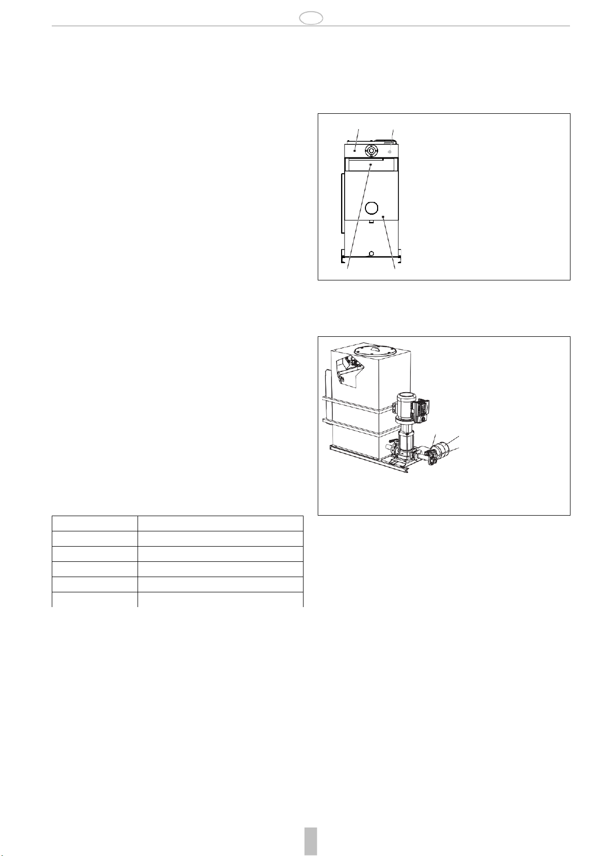
3. Description...................................................................................... 7
3.1 Overview .......................................................................................... 7
3 1.1 Installation type 7
3.2 Intended use..................................................................................... 7
3.3 Non-intended use.............................................................................. 7
3.4 Version............................................................................................. 8
3.5 Options............................................................................................. 8
4. Function.......................................................................................... 8
4.1 Inlet side........................................................................................... 8
4.2 Outlet side ........................................................................................ 8
4.3 Indicator LED.................................................................................... 8
4.4 Mode of operation............................................................................. 8
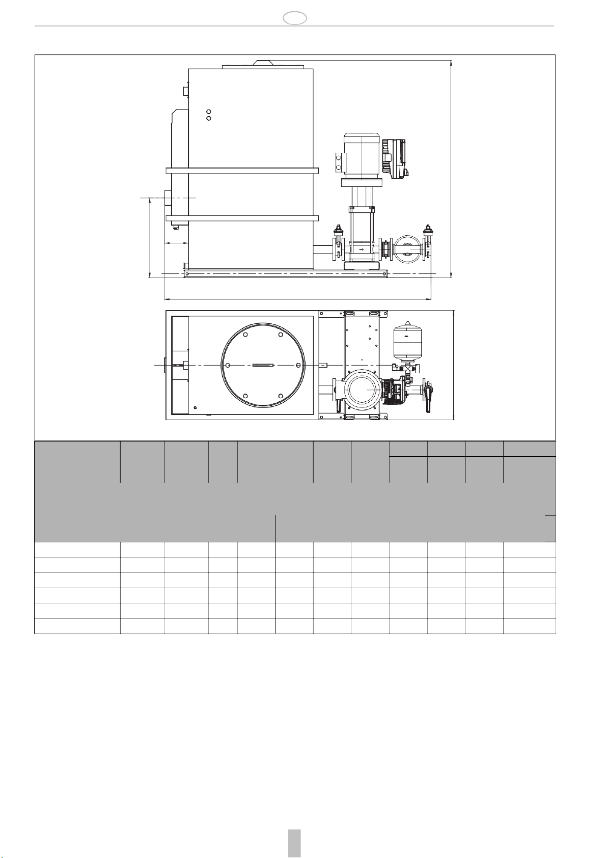
5. Technical data................................................................................. 9
5.1 Noise expectancy values................................................................... 9
5.2 Authorised environmental conditions ................................................. 9
6. Shipping........................................................................................ 10
6.1 Check condition upon delivery......................................................... 10
6.2 Transportation ................................................................................ 10
7. Assembly ...................................................................................... 10
7.1
General safety instructions...............................................................10
7.2 Installation according to EN1717......................................................10
7.3 Inspection before assembly .............................................................11
7.3.1 Installation site 11
7.4 Installing the compact booster unit ...................................................11
7.5 Installing the pipelines .....................................................................11
7.5.1 Connecting the overflow 11
7.5.2 Installing the compensator (optional) 11
7.6 Buffer tank ......................................................................................11
7.7 Installing valves...............................................................................11
7.8 Electrical connection........................................................................11
7.8.1Safety instructions 11
7.8.2Connection specifications 11
7.9 Standby indicator.............................................................................11
8. Start-up..........................................................................................12
8.1 Safety instructions for start-up..........................................................12
8.2 Start-up requirements......................................................................12
8.3 Initial operation................................................................................12
8. 3. 1
Change switch-on pressure 12
8.4 Switching the system on ..................................................................12
8.5 Start-up checklist.............................................................................13
9. Operation.......................................................................................13
9.1 Function of operating panel..............................................................13
10. Maintenance ..................................................................................13
10.1Safety instructions for maintenance..................................................13
10.2Inspection .......................................................................................13
10. 2. 1
Buffer tank 13
10. 2. 2
Monitoring Operation 13
10.2.3Checklist for Inspection 14
10.3Maintenance ...................................................................................14
10. 3. 1
Settingthe precharge pressure for the membrane pressure vessel
14
10. 3. 2
ning the dirt trap 14
10. 3. 3
Checklist for maintenance work 14
11. Troubleshooting............................................................................14
12. Shut-down, restart.........................................................................14
12.1Shutting down the compact booster unit ...........................................14
12.2Restarting the compact booster unit .................................................14
13. Storage ..........................................................................................14
13.1Short-term storage...........................................................................14
13.2Storage/Preservation.......................................................................14
13.3Storage conditions...........................................................................14
14. Disassembly, disposal ..................................................................15
14.1Safety instructions for disassembly...................................................15
15. Spare parts ....................................................................................15
16. Start-up protocol ...........................................................................16
17. Declaration of no objection ...........................................................17
18. Proof of Maintenance ....................................................................18

GB
MU1H-1376GE23 R1020 - Translation of original
3
1. Safety Guidelines
1.1
Safety instructions in this manual
Danger
Places with thissign signify that death, severe bodily injury or significant
property damage will occur if the appropriate precautionary measures
are not followed!
Warning
Places with thissign signify that death, severe bodily injury or significant
property damage may occur if the appropriate precautionary measures
are not followed!
Caution
Places with this sign signify that small bodily injury or slight property da-
mage may occur if the appropriate precautionary measures are not fol-
lowed!
Places with this sign provide technical information and tips on usage
that damage to the machine must be avoided.This symbol is not a safe-
ty indication.
Places with this sign provide information about possible hazards to the
environment
Please notice that a safety symbol never can replace the text of the
safety instruction itself - the text of the safety instruction must be read
entirely!
1.2
Safety instructions in the system
Danger of burning on hot surfaces of pump housing
1.3
General safety instructions
This manual contains basic instructions which are to be observed in trans-
port, assembly, start-up, operation, maintenance, shut-down, storage and
waste disposal.
The following safety instructions have to be observed while operating the
compact booster unit:
•When using the compact booster unit, the data, operation and usage
conditions specifically authorised in the technical data sheet and the
operating manual have to be observed.
•Never exceed the permissible limits pertaining to pressure, temperature,
etc. as stated in the documentation.
•Observe all safety instructions as well as the operating instructions of the
manual.
•Instructions that are directly attached to the system have to be observed
and must be kept completely legible. This applies for exampleto:
-Safety instructions
-Arrow for rotation direction
-Connection labels
-Type label
•Before assembly and start-up, the manual has to be read by the operator
as well as by the responsible technical/operating personnel and has to be
stored at the site of the compact booster unit at all times.
•Installation and maintenance work may only be performed by authorised
specialist personnel with the appropriate tools.
•The technical condition of the compact booster unit has to be checked
regularly (at least once a year) by the operating company.
•The local safety and accident regulations have to be observed when
operating the compact booster unit.
•The general technical rules must be observed when planning the usage
and operating the device.
•Modification of the compact booster unit is not permitted and leads to the
loss of warranty.
•Afteran interruption of the electrical or fluid supply, a defined or controlled
re-run of the process must be ensured.
•The operator is responsible for complying with local regulations that are
not covered by the manual.
1.4
Further safety regulations
Besides the safety instructions presented in this manual and its intended
use, the following safety regulations are valid:
•Accident prevention regulations, safety and operating regulations
•Safety regulations for handling hazardous substances
•Applicable standards and laws
1.5
Unauthorised operation types
The limits that are stated in the documentation have to always be complied
with. The delivered system is only guaranteed to operate reliably when it is
used as intended.
1.6
Software changes
The software was especially developed for this product and has been
thoroughly tested. Changing or adding software or software parts is not
permitted. Excluded from this are the software updates provided by Honey-
well.
1.7
Residual dangers in handling the compact booster unit
Danger and adverse effects may result from use of the compact booster unit
•for the body and life of the operator or third person
•for the compact booster unit itself
•to other property.
The basis for safe and error-free operation of the compact booster unit is
knowledge of the instructions for safety and operation in this manual.

GB
4
Translation of original - MU1H-1376GE23 R1020
1.7.1
Mechanical residual dangers
During normal operation, no danger is threatened from mechanical components.
1.7.2
Residual dangers pertaining to fluids
During normal operation, no danger is threatened by hydraulic components.
Hazards might result solely under the following conditions.
Danger area
Type of hazard
Reduction of hazard
Pipelines
Injury through high pressure
Clear pipelines of pressure and medium prior to assem-
bly, maintenance, shut-down!
1.7.3
Residual electrical hazards
During normal operation, no danger results from the electrical equipment of the compact booster unit.
Hazards might result solely under the following conditions.
Danger area
Type of hazard
Reduction of hazard
Injury from cables
Danger to life !
Electric shock of 230/400V from electric voltage
Connect up protective earth system!
Always switch off power supply and secure against swit-
ching on again during maintenance and servicing work!
Comply with the valid accident prevention and safety re-
gulations for electrical devices!
Electrostatically endangered
components / subassemblies
The device contains electronic componental elements that react
sensitively to electrostatic discharge (ESD). Contact with electro-
statically charged persons or objects endangers these compo-
nental elements. Worst case scenario: they will be immediately
destroyed or fail after start-up.
Comply with requirements according to EN 100 015 - 1,
in order to minimise or avoid damage through shock-
type
electrostatic discharge!
Do not touch electronic componental elements when the
power supply is on!
1.7.4
Residual biological hazards
During normal operation, no biological danger results from the compact booster unit.
Hazards might result solely under the following conditions.
Danger area
Type of hazard
Reduction of hazard
Buffer tank
Danger of microbial contamination
Clean the buffer tank regularly!
1.7.5
Residual chemical hazards
During normal operation, no chemical danger results from the compact booster unit.
Hazards might result solely under the following conditions.
Danger area
Type of hazard
Reduction of hazard
Use of detergents
Danger through contact with or breathing in dangerous fluids, ga-
ses, fumes, vapours or dust
Wear personal safety equipment!
Pay attention to the safety specifications sheet of deter-
gent manufacturers!
1.7.6
Consequences and dangers that result from not observing the manual
•Not observing this manual will lead to loss of the warranty and make damage claims invalid.
•Failure to observe the manual can lead, for example, to the following dangers:
-Hazard to persons caused by electrical, thermal, mechanical, and chemical influences
-Loss of important product functions
-Failure to perform required maintenance and service measures
-Environmental hazard caused by leakage of hazardous substances

GB
MU1H-1376GE23 R1020 - Translation of original
5
1.8
Basic Safety Measures
1.8.1
Keep information available
This manual has to be stored. It has to be ensured that all persons who
operate the compact booster unit have access to the manual at all times.
1.8.2
For environmental protection
When operating or servicing the compact booster unit, the regulations
concerning waste avoidance and the proper recycling or disposal of wa-
ste must be observed.
Particular attention must be paid that materials and agents dangerous
to the groundwater such as fats, oils, coolants, solvent-based liquid de-
tergents, etc. do not pollute the ground or access the sewage system.
These materials must be caught in suitable tanks, stored, transported
and properly disposed of.
1.8.3
Modifications to the compact booster unit
When using externally procured parts, there is no guarantee that these are
designed and constructed to tolerate demands made upon them or whether
they comply with safety regulations.
For safety reasons, no unauthorised modifications may be made to the
compact booster unit.
Parts and special equipment not delivered by Resideo are also not autho-
rised by Resideo for use.
1.9
Duty of due care of the operator
This compact booster unit was designed and constructed according to a risk
assessment and after careful selection of the harmonised standards that
apply, as well as according to further technical specifications. It thus
complies with best practice and guarantees the highest safety standard.
This level of safety can only be attained during operational practice if all
required safety measures have been taken. It is the duty of care of the
operator of the compact booster unit to plan these measures and enforce
their implementation.
In particular, the operator must ensure that
•the compact booster unit is only operated as intended
•the compact booster unit is only operated in perfect workingcondition.
•the manual has to be kept legible at all times and stored on-site with the
compact booster unit.
•the compact booster unit is assembled, commissioned, operated, main-
tained, and shut down solely by sufficiently qualified and authorised
personnel.
•this personnel is regularly instructed on all relevant questions of work
safety and environmental protection, and has also read and understood
the manual and particularly the safety instructions itcontains.
•none of the safety and warning signs attached to the compact booster unit
are removed and all remain legible.
•a hazard assessment (according to the Safety at Work Act § 5) is
conducted to detect further hazards that may arise from the particular
working conditions on-site where the compact booster unit is operated.
•all further information and safety instructions which arise from the hazard
assessment process shall be summarised in operating instructions
(according to the work equipment regulation § 6).
•the drain output lines are sufficiently dimensioned
1.10
Safety instructions for the operator/operating personnel
•Eliminate hazards caused by electrical energy (for details refer to the
country specific regulations and/or local power supplycompanies).
1.11
Safety instructions for maintenance, inspections and
assembly work
•Alterations or modifications of the system are only permitted with the
consent of the manufacturer.
•Use only original parts or parts authorised by the manufacturer.
•Use of parts other than those authorised may lead to loss of liability for
any damage they may cause.
•Perform service on the system only when the machine is off.
•The pump housing has to be at ambient temperature.
•The pump housing has to be depressurised and empty.
•The procedures described in the manual for shutting down the system
have to be observed under all circumstances.
•Reinstall safety equipment and protective devices and activate them
again immediately after work on the system has been completed. Before
starting up again, observe the start-up checklist.
•Keep unauthorised persons (e.g. children) away from the system.
1.12
Requirements for operating personnel
1.12.1Operating personnel
This compact booster system may only be asembled, started, maintained,
and shut down by persons who have been trained, instructed and authorised
to do so.
In some cases, training can be arranged by the manufacturer if asked by the
operator.
Training or personnel to operate system may only be conducted under the
supervision of specialised technicians.
The relevant authorisations of the personnel are to be specified by the
operating company in the form of an operating instruction.
Over and above this, special qualifications are required for the following
tasks:
•Only electricians may perform work on electrical equipment.
•Assembly, maintenance, servicing and repair work may only be
performed by qualified, specialist personnel
The basic regulations on work safety and accident prevention are to be
observed.
1.12.1.1Qualified personnel
Qualified personnel are persons who on account of their training, experience
and instruction also their knowledge of the relevant norms, regulations, acci-
dent prevention regulations and operating conditions, including those
persons responsible for the safety of the system, have been authorised to
perform the relevant and required tasks, meanwhile being able to recognise
and avoid dangers. This includes required knowledge of First Aid measures
and the local ambulance services and facilities.
1.13
Personal safety equipment
No personal safety equipment is required to operate the compact booster
unit.

GB
6
Translation of original - MU1H-1376GE23 R1020
2. General information
The manual is a part of the series and the versions as mentioned on the title
page. The manual describes the safe and proper use in all modes of opera-
tion.
The type label indicates the series and size, the most important operating
data and the order number. The factory number/serial number describes the
identifies the system uniquely and serves this purpose for all further busi-
ness transactions.
In order to maintain the warranty, in the event of damage immediately
contact the nearest Resideo service centre.
2.1
Conformity with the following norms
Pump unit: Machinery Directive 2006/42/EG
Pump unit: EMC Directive 2004/108/EG
Frequency inverter: EMC Directive2004/108/EG
Frequency inverter: Low voltage directive 2006/95/EG
2.2
Warranty and liability
As a matter of principle, the general sales and delivery terms of the Honey-
well Company apply. Warranty and liability claims for injury to persons and
damage to property are ruled out if they arise from one or more of the follo-
wing causes.
•Non-intended use of the compact booster unit
•Improper assembly, start-up, operation and maintenance of the compact
booster unit
•Failure to comply with the instructions in the manual concerning transport,
storage, assembly, start-up, operation, maintenance, and service of the
compact booster unit
•Unauthorised constructional modifications of the compact boosterunit
•Improperly performed repairs
•Catastrophes through effect of a foreign object or force majeure
2.3
Storage and perfect condition
This instruction manual is a part of the compact booster unit and has to be
complete and accessible at all times. Any instruction or page that is missing
has to be replaced immediately.
2.4
Illustrations
The illustrations used are examples of one possible version of the compact
booster unit and might differ in individual cases from the actual compact
booster unit version.
2.5
Symbols
1. Start of a task description
2. Next work step
- Result of an action
•List of several options
Reference to other documents
2.6
Other applicable documents
Product data sheet CBU146
Operating instructions of the operating company
Data sheets
Documentation for the circuit diagram
Wiring scheme
Instructions for the frequency inverter
Instructions for the pump
Instructions for the pressure sensor
Instructions for the throttle valve
Instructions for the membrane pressure vessel
Instructions for the check valves
Instructions for magnetic valves
Declaration of Conformity
2.7
Glossary
EN 1717
European standard that specifies technical regulations for potable water
installations.
Noise expectancy values
The expected noise emission, stated here as sound pressure level (SPL) in
dB(A).
Membrane pressure vessel
The membrane pressure vessel is for compensating pressure drops in the
pipeline network behind the compact booster unit, that can occur because of
loss of minimal quantities.
That minimises the frequency of operation of the compact booster.
Certificate of no objection
A certificate of no objection is a declaration that the system has been
cleaned properly so that parts that have been in contact with medium are not
dangerous for health and environment.
Danger source
Consequence of non-compliance
Avoidance
Pictogram Danger classification

GB
MU1H-1376GE23 R1020 - Translation of original
7
3. Description
Speed controlled compact booster unit with a vertical high-pressure pump as
a safety device to separate potable water from category 5 fluids according to
EN 1717 .
Fully automatic, fully wired Compact Booster Unit with modular design
comprising a single pump system and a buffer tank for the hygienic separa-
tion of potable water and category 5 fluids according to DIN EN 1717, on a
common base frame.
The modular design makes it possible to disconnect modules for installation
in buildings with limited space.
The system is switched on and off regulated by pressure, the flow rate is
controlled via frequency inverter..
Separation of systems as a means to protect potable water from being
contaminated by fluids of the category 5 according to EN 1717
Pump medium Non-potable water
Without aggressive, abrasive and solid
components
Flow rate see chapter 5. Technical data
Pumping head Adjustable within the range of pumpcharacte-
ristics, preset to 60m
see chapter 5. Technical data
Medium temperature up to 30 °C
Ambient temperature up to 40 °C
Nominal pressure PN 16
Inlet pressure 1.5 - 8 bar (depending upon the model)
Supply voltage 3/PE, AC 400 V, 50 Hz
3.1
Overview
The system comprises one multi-speed high-pressure rotary pump with inlet
and outlet shut-off valves. They can be locked with padlocks against
unauthorised closing. They make it possible to disassemble the pump or the
check valves without having to empty the pipeline system. The check valve
on the pumping side prevents liquid from backing up on the pump and
flowing backwards through it, and it relieves the floating ring seal.
The fully automatic Compact Booster Unit with compact design comprising:
•vertical high-pressure pump
•frequency converter adapted on the motor to ensure a constant supply
pressure to the points of consumption
construction and operation is according to DIN 1988,EN 1717 and EN
13077.
1
4
3
2 5 8 6 7
Figure 1: CBU146 Construction
3.1.1
Installation type
•Fixed installation
3.2
Intended use
The compact booster unit may only be operated in such areas as described
in the other applicable documents.
Non-intended operation of the compact booster unit can result in danger to
persons, systems, the surroundings and the environment.
•Operate the compact booster unit only if it is in perfect workingcondition.
•Do not operate the compact booster unit if it is only partiallyassembled.
•The compact booster unit may only be used to pump the medium as
described in the documentation of the respective version.
•Never operate the compact booster unit without pump medium.
•Observe the values for minimum pumping rates (avoiding damage
because of overheating, storage damage, ...).
•Observe the values for maximum pumping rates (to avoid damage due to
overheating, floating ring seal damage, cavitation damage, storage
damage, ...).
•Do not throttle the input of the compact booster unit (to avoid cavitation
damage).
•Other modes of operations, if not mentioned in the documentation, have
to be coordinated with the manufacturer.
3.3
Non-intended use
The compact booster unit is not designed for operation outside. Tempera-
ture, light and moisture can lead to malfunctions and damaging devices.
•Do not operate the compact booster unit outside.
•Operate the compact booster unit only as intended.
•Do not fill aggressive or flammable medium into the medium lines of the
system.
•No mechanical stress on housings (e.g. by depositing objects or as a
step).
•Do not perform any external modifications on the device housing. Do not
paint housing parts and screws!
•Do not disassemble the compact booster unit more than is necessary for
purposes of installation and maintenance.
1
Inlet
5
Base frame
2
Buffer tank
6
Check valve
3
Display
7
Inlet shut-off valve
4
Pump
8
Outlet shut-off valve

GB
8
Translation of original - MU1H-1376GE23 R1020
3.4
Version
Speed-controlled compact booster unit with:
•1 normal sucking, vertical high-pressure rotary pump with all components
in contact with the medium made of stainless steel
•High efficiency motor with frequency inverter, energy efficiency class IE4
according to IEC-CD 60034 - 30 ED. 2
•Check valve
•Shut-off valve on the inlet and outlet sides
•Diaphragm expansion vessel on the outlet side as vessel
•Pressure sensor on the pressure side
•Vibration damper between pump and base frame
•Pressure gauge display
•Shut-off valve, lockable
•Piping made of stainless steel
•The system is connected to the installation pipeline with G1 ¼", G2" or G2
1/2" (depending on version)
•Base frame made of coated steel
Self-cooled frequency converter adapted on the motor
Refer to instructions of frequency inverter
Buffer tank made of polyethylene with:
•Non-circular, free overflow according to EN 13077, Type AB
•Drainage connection with integrated siphon trap:
DN100 for CBU146-32A-060 and CBU146-40A-060
DN150 for CBU146-50A-060, CBU146-65A-060,
CBU146-65B-060 and CBU146-80B-060
•Tank volume according to DIN 1988-500 or individual approved
•Potable water backfeed via float valve, suitable for potablewater
Switch cabinet consists of:
•Power supply connection via 3/N/PE, AC 400V, 50Hz
•Lockable emergency stop main switch (repairswitch)
•LED, green for normal function, yellow for warning, red for alarm and
description text in the display
•Motor protection device (Included in the frequency inverter)
•Terminal strip/clamps with labels for all connections
•Plug connectors to connect easily with the electrical equipment fitted to
the supply container.
Messages sent via potential-free contact for
•Alarms and warnings
•Pump run indicator
3.5
Options
4. Function
4.1
Inlet side
On the inlet side there is a buffer tank. It has a floating valve on its inlet to
refill water. The water level is measured with two float switches. They send
messages in the case of water shortage and overflow. The overflow has an
integrated siphon trap and can be directly connected to the drain.
1 2/3 1 Buffer tank
2Floating valve
3Float switch
4Overflow
5Siphon trap
4 5
Figure 2: CBU146 Inlet side
4.2
Outlet side
On the outlet side there is a diaphragm expansion vessel as well as a pres-
sure sensor and a pressure gauge.
1Diaphragm expansion
vessel
2Pressure sensor
3Pressure gauge
2 1
3
Figure
3: CBU146 Outlet side
4.3
Indicator LED
LED, green for normal function, yellow for warning, red for alarm and
description text in the display
4.4
Mode of operation
The pump is switched on based on pressure, and off based on quantity, by a
fully-automatic control unit. If a pre-set pressure setting is exceeded, the
pump switches on and the frequency converter regulates the compact buster
unit to the set value, so that a constant pressure is always available. The
speed decreases as consumption reduces and the compact booster unit
switches off after a set minimum run time (0 to 600 seconds, default set to
60 seconds).
CBU146-32A-060
refer to technical data for type selection
CBU146-40A-060
refer to technical data for type selection
CBU146-50A-060
refer to technical data for type selection
CBU146-65A-060
refer to technical data for type selection
CBU146-65B-060
refer to technical data for type selection
CBU146-80B-060
refer to technical data for type selection

GB
MU1H-1376GE23 R1020 - Translation of original
9
5. Technical data
175
L
Type
Volumetr
Qmin
Volumetr
Qmax
max.
pum
Connect
Nominal
performa
Usable
vo
Length
Width
Height
Weight
[m3/h]
[m3/h]
[m]
Inlet
Pump
P
2
[kW]
[l]
[mm]
[mm]
[mm]
[kg]
CBU146-32A-060
0.6
7.0
86
G11/4"
DN32
2.2
350
1543
800
1185
195
CBU146-40A-060
1.1
11.0
89
G1
1
/
4
"
DN40
3.0
350
1600
800
1185
218
CBU146-50A-060
1.6
19.0
85
G2"
DN50
5.5
540
1965
800
1600
324
CBU146-65A-060
4.0
28.0
81
G2"
DN65
7.5
540
1990
800
1600
346
CBU146-65B-060
4.0
34.0
100
G2
1
/
2
"
DN65
11.0
540
1990
800
1600
444
CBU146-80B-060
4.6
43.0
86
G2
1
/
2
"
DN80
15.0
540
2000
800
1600
411
5.1
Noise expectancy values
Refer to pump manual for noise value of the pump.
5.2
Authorised environmental conditions
Ambient temperature 5°C ...40°C
Relative air humidity max. 60% r.h. at 40 °C ambient
temprature
c flow rate
587 ±10
c flow rate
p head*
on
nce
lume
H
B

GB
10
Translation of original - MU1H-1376GE23 R1020
6. Shipping
6.1
Check condition upon delivery
1. Check the contents of each package for damage upondelivery.
2. In the case of transport damage estimate the extent, document the
damage and notify Resideo immediately in writing.
6.2
Transportation
Danger
Overturning the system
Danger of being crushed by system!
Never get the system tangled in electrical lines.
Observe the local safety regulations.
Observe the weight and mass centre.
Only use appropriate and authorised means of transportation,
for example fork lift or hand lift.
Warning
Installation on non-level and non-structural installation sites
Personal and property damage!
Ensure sufficient compressive strength according to class
C12/
15 for concrete in the exposition class X0 according to EN 206-
1.
The installation site has to be solid, level and horizontal.
Observe the weight information.
The compact booster unit is attached to wooden rails and wrapped in
foil for transport and temporary storage. All connection interfaces have
protective lids.
The system can be divided into three parts, to facilitate transportation if
necessary. For this purpose, the plug connections of the system to the
switch cabinet have to be disconnected, the hydraulic connections of the
pump suctionside of the flange have to be disconnected, and the buffer tank
has to be disconnected from the base frame.
1. Selecting the adequate transportation device for the weight class.
2. Transporting the system to the installation site.
- divide into three parts if necessary.
3. Detach the wooden rails of the system and dispose of them.
4. Lift the system with a suitable lifting device and place it carefully at the
installation site.
5. Reassemble the divided system and restore the mechanical and electrical
connections.
7. Assembly
7.1
General safety instructions
Danger
Danger for persons, near-by systems and the the environment that
arises from the non-intented use of the compact booster unit.
Operate the compact booster unit only as intended.
Injury through high pressure in the system.
Pipelines have to be depressurised and emptied before assem-
bling the compact booster unit.
Danger through uncontrolled start-up of the system
Secure the system against unintentional operation during instal-
lation.
After an interruption of the electrical or fluid supply, a defined or
controlled re-run of the process must be ensured.
Warning
The compact booster unit is not designed for operation outside.
Temperature, light and moisture influences can lead
to malfunctions and damage todevices.
Do not use the compact booster unit outside.
Danger through improper installation
Personal and property damage!
Performance of tasks only by qualified personnel (see section
1.12).
Installation on non-level and non-structural installation sites
Personal and property damage!
Ensure sufficient compressive strength according to class
C12/
15 for concrete in the exposition class X0 according to EN 206-
1.
The installation site has to be solid, level and horizontal.
Observe the weight information.
Caution
Damaged or improperly installed compact booster unit.
Malfunctions
Do not damage the compact booster unit and only install it if it
is clean and fully functional.
Install the compact booster unit according to the described
instructions.
Install free of voltage and of bending moments.
Individual housing parts are to be removed for the installation
process, which means that theIP protection of the device is no longer
complete.
No water is to enter into the device interior during assembly.
7.2
Installation according to EN1717
Accomodate the compact booster unit in a technical centre or in a frost-free,
well ventilated, lockable room that is not used for anything else. Hazardous
gases should never enter the installation room. A sufficiently dimensioned
dewatering connection (drain connection or similar) is required (observe
EN 12056).
Usable volume tank
Dewatering capacity
540 l
25 m3/h
350 l
25 m
3
/h
Table 6: Usable volume/dewatering capacity
Do not operate the compact booster unit near living rooms and
bedrooms.
Ifcompensators are usedto damper vibrations, their durability has to be
ascertained.
Compensators have to be able to be easily replaced.

GB
MU1H-1376GE23 R1020 - Translation of original
11
7.3
Inspection before assembly
7.3.1
Installation site
Sufficient noise insulation for the building is ensured due the compact
booster unit`s safety store.
The system has to be installed above the flood level. Provide a suitable
lifting device for underfloor installation.
1. Inspect the building architecture.
-The architecture of the building has to be prepared according to the data
sheets.
-The concrete foundation is true to size and completely solid.
7.4
Installing the compact booster unit
Warning
The system is top heavy
Danger of injury!
Secure the system so that it cannot tip over before it has been
permanently anchored.
Anchor the system securely to the foundation.
Make allowance for space for operating and maintenance tasks.
1. Remove the packaging before installing the system.
2. Connect the system refilling and discharge pressure lines with the distri-
bution lines on the refilling and discharge side (DIN 1988).
3. Mark the installation holes on the floor as desribed in the datasheet.
4. Drill holes (maximum Ø12 mm).
5. Insert suitable, proper sized dowels.
6. Position the system for installation.
7. Anchor the system solidly to the foundation with adequate bolts.
To avoidthe transfer of pipeline forces andstructure-borne sound tothe
7.6
Buffer tank
Caution
Dirt in the system
Damage to the pumps!
Rinse the tank before filling it.
Rinse the tank and the integrated odour trap regularly.
The DIN 1988 allows for the installation of a pressure-free buffer tank
together with the compact booster unit. The same regulations apply for
their installation as for the compact booster unit.
The buffer tank made of polyethylene fulfils the requirements of
EN 1717 and EN 13077, with free drain type AB.
7.7
Installing valves
All additional valves in the terminal lines such as sliders, water meters and
check valves have to be dimensioned according to the values stipulated by
the competent water distribution company.
7.8
Electrical connection
7.8.1
Safety instructions
v compact booster unit, it is recommended to install compensators with a
tie bar.
7.5
Installing the pipelines
Always install pipelines so that they are free of tension.
The use of compensators with tie bars (refer to the accessories section)
is recommended.
7.5.1
Connecting the overflow
Caution
Overflow not connected
Danger of flooding the installation room!
Lead the overflow line to a drain with adequate dewatering
capacity (connection DN150).
1. Lead the pipeline to the drain.
7.5.2
Installing the compensator (optional)
Ifcompensators are used to damper vibrations, their durability has to be
ascertained.
Compensators have to be able to be easily replaced.
Danger
Sparks and radiant heat
Fire hazard!
Take approriate measures to protect the compensator during
welding work in the vicinity.
Caution
Leaky compensator
Danger of flooding the installation room!
Check regularly for rips and blisters, exposed material or other
defects.
1. Install the compensator in the pipeline without tension.
- Never correct misalignment and offset pipes with the compensator.
2. Fasten bolts equally cross-wise.
- The bolt ends should not protrude from the flange.
Do not paint the compensator and always protect it against oil.
The compensator has to be accessible on the compact booster unit at
any time for inspection purposes and forthis reason should not be inclu-
ded in the pipe insulation.
The compensator is subject to wear.
7.8.2 Connection specifications
Power supply connection 3/N/PE, AC 400V, 50Hz
The circuit diagrams of the respective systems are kept in the switching
device and should always remain there. The documentation included
withthe switch cabinet contains a list of electronic parts. Please always
specify the circuit diagram number when ordering spare electronic
parts.
The diameter of the electrical supply line has to be determined according
to the total connection value.
7.9 Standby indicator
The system standby mode has to be registered by the operator or their
contractors at the responsible authority (most commonly WVU or factory
inspectorate). Before starting the system, the author has to certify that the
prerequisites for connection are fulfilled.
Before the system is connected to the mains power supply, the operator has
to read the relevant VDE regulations.
The electrical supply lines must only be installed by companies that are
authorised to do such work.
Danger
Danger of injury from electric voltage.
Highshockcurrentsandburnsfromdirectandindirectcontactwith
live parts.
Turn off the power supply before assembling the compact
booster unit and secure it from being turned on.
Non- or erroneously-connected cables
Malfunctions, which endangerthe safety of operating personnel.
Work on electrical equipment may only be performed by specia-
list electric technicians.
Observe regulation IEC 30364 (DIN VDE 0100) and for explo-
sion protection IEC 60079 (DIN VDE 0165).
Faulty mains connection
Damage to the electricity network, short circuit!
Observe the conditions for technical connections of the local
power supply companies.
Wrongly wired connections
Destruction of electrical / electronic components.
Work on electrical equipment may only be performed by specia-
list electric technicians.
Improperly connected wiring and lines (e.g. too small bend radius)
Smouldering and fires from cables.
Work on electrical equipment may only be performed by specia-
list electric technicians.
Live cable ends and components
Make sure the protective earth system is connected throughout.

GB
12
Translation of original - MU1H-1376GE23 R1020
8. Start-up
Performance of tasks only by qualified personnel (see section 1.12).
8.1
Safety instructions for start-up
Warning
Danger from improper operation.
Malfunctions
Before starting, the manual has to be read by the operator as
well as by the responsible technical/operating personnel and
has to be stored at the site of the compact booster unit at all
times.
Adhere to local safety and accident regulations when starting
the compact booster unit.
Damaged or improperly installed compact booster unit.
Malfunctions
Check the compact booster unit for obvious signs of damage;
eliminate any defects immediately or alert the supervising
personnel. The compact booster unit may only be operated in
perfect working order.
Inform yourself sufficiently about
•the equipment of the compact booster unit
•the functionality of the compact booster unit
•the close surroundings of the compact booster unit
•the measures to be taken in an emergency
8.2
Start-up requirements
Caution
Dry running pump
Damage to the pump/system!
Ensure that there is no water shortage.
The responsible authorities have to be informed before start-up and be-
fore testing.
Before start-up of the compact booster unit, the following points have to be
ensured:
•The compact booster unit has to be connected to all protective equipment
according to the regulations.
•The relevant VDE and country-specific regulations have to be adhered to
and fulfilled.
•The buffer tank has to be full of water.
•The refilling has to function properly.
•Flange connections have to be checked if they are fastenedtightly.
•Pipe fittings between pump and pipeline have to be tightened.
•In and output openings for air-cooling of the motor arefree.
•The precharge pressure of the membrane pressure vessel ischecked.
•All shut-off valves in the system are open.
8.3
Initial operation
The initial start-up should be performed by Resideo technical staff.
Caution
The pipeline must be free of residue
Danger of damaging the pump/compact booster unit!
Before start-up (and testing) make sure that pipelines and
compact booster unit are free of residues.
Caution
No pressure on the output side
Pump starts when main switch is turned on!
During start-up and also during automatic mode, the pump
starts as soon as the main switch is turned on, because the
systemreceives astart command from the pressuresensor due
to the lack of pressure on the output side. This is noteven
prevented if the motor protection switch is also activated.
In case of water shortage the system does not start.
The start-up, or testing mode, of the compact booster unit may only be
initiated if all VDE regulations have been fulfilled.
Floating ring seals may briefly show signs of leakage during start-up,
but no longer after a short period of operation.
1. Connect electrical circuit on-site.
2. Connect water supply for refilling on-site.
3. Open or loosen the ventilation screws on the pump (refer to operating/
assembly instructions).
4. Slowly open the shut-off valves on the input side and fill the system until
water runs out of every ventilation borehole.
5. Close the ventilation screws, tighten pump ventilation lightly.
6. Set main switch to I.
7. Check direction of pump rotation.
-The direction of rotation has to be the same as the direction shown by the
arrow on the motor. If it is rotating in the wrong direction, two phases of
the inlet have to be exchanged.
8. Slowly open the shut-off valve of the output and use the pressure gauge
to check if the system starts if the switch-on pressure is reached (refer to
Chapter 5.).
-If the switch-on pressure is set to the wrong value, it has to be changed
as described in chapter 8.3.1.
9. Slowly close the shut-off valve of the output and use the pressure gauge
to check if the system shuts off when the switch-off pressure is reached
(refer to Chapter 5.).
-If the switch-on pressure is set to the wrong value, it has to be changed
as described in chapter 8.3.1.
10.Let the pump run again with the output shut-off valve open, loosen the
ventilation screw and let the rest of the air out.
11.Close the ventilation screw tightly.
12.Check if the pump runssmoothly.
8.3.1
Change switch-on pressure
1. Click on the settings key indicated by as spanner symbol
2. Move up and down using the arrow keys to setting value1-2-3-3
3. Press OK key
4. Move up and down using the arrow keys to desired setting value for the
discharge pressure in bars.
5. Press OK key confirm the set value
6. For any further information please Refer to instructions of frequency
inverter
8.4
Switching the system on
1. Secure the shut-off valves of the in and output against beingclosed.
2. Operate the main switch to supply the system with voltage.
- The green LED indicates that the unit is ready to use.

GB
MU1H-1376GE23 R1020 - Translation of original
13
8.5
Start-up checklist
Work steps
finished
1
Read instructions.
2
Check the voltage supply and compare with the values
on the type label.
3
Check the grounding system (by measurment).
4
Check the mechanical connection to the water supply
system. Tighten the flanges and the screws.
5
Fill and ventilate the compact booster unit from the input
side.
6
Check the refilling.
7
Check the switching device to see if all electrical lines
are still securely plugged into the clamps.
8
Check the rotation direction.
9
Check the switch-on and switch-off pressure, correct if
necessary.
11
Venting the pump a second time, after it has been run-
ning for a few minutes (5 to 10).
12
Set the switch to automatic.
13
Check the precharge pressure (refer to Chapter 10.3.1).
14
Secure the shut-off valves of the in and output lines
against being closed
15
Circumstances regarding the system that are not the
same as stated in our documentation or ordering data,
have to be noted in the start-up protocol.
16
Fill out the start-up protocol with the operator and show
the operator how the machine functions.
9. Operation
9.1
Function of operating panel
Refer to instructions of frequency inverter
10. Maintenance
Maintenance should be performed by Resideo technicalstaff.
•If necessary contact the service department at Resideo.
Performance of tasks only by qualified personnel (see section 1.12).
10.1
Safety instructions for maintenance
Danger
Unintentionally switching on the compact booster unit
Danger to life!
The compact booster unit has to be voltage free for all repairs
and maintenance work. Turning off the system with the motor
protectionswitch does not securely shut off the motor inlet lines.
Only perform maintenance work on the compact booster unit if
you are sure that the compact booster unit is free ofpower.
Secure the compact booster unit against being switched on
unintentionally.
Danger
Danger of injury from electric voltage.
Highshockcurrentsandburnsfromdirectandindirectcontact with
live parts.
Turn off the power supply before maintaining the compact
booster unit and secure it from being turned on.
Warning
Components and lines under pressure
Personal and propertydamage!
Before work is done on pressure-retaining components, the
pump has to be depressurised!
Disconnect the pump from the power supply!
Warning
Inappropriate lifting/moving of heavy modules or components
Personal and property damage!
When moving heavy modules or components, use suitable
transport devices, lifting devices and lifting accessories.
Warning
Unqualified persons working on the compact booster unit
Danger of injury!
Only let specially qualified personnel perfom repair and mainte
-
nance work.
Caution
Inappropriately maintained compact booster unit
Theproperfunctionof the compactboosterunit cannolongerbe
ensured!
Maintain the compact booster unit regularly.
Set up a maintenance schedule for the compact booster unit
that focuses especially on the pump lubrication, shaft seal and
clutch.
Always observe the safety regualations and instructions.
Observe the instructions for working on the pumps.
In case of damage, please contact our service department.
By setting up a maintenance schedule, the required maintenance to
avoid expensive repairs and achieve fault-free and reliable functioning
of the compact buster unit is held to a minimum.
10.2
Inspection
To ensure that the compact booster unit can be operated reliably, the
required inspections have to be conducted on time.
10.2.1
Buffer tank
Caution
Dirt in the system
Damage to the pumps!
Rinse the tank before filling it.
Rinse the tank and the integrated odour trap regularly.
1. Rinse the inlet to the buffer tank if necessary.
2. Rinse the tank and the integrated odour trap regularly.
3. Check if the overflow is sealed and clean.
10.2.2
Monitoring Operation
Danger
Filling wrong gas in expansion vessel
Danger of poisoning!
Only fill the pressure pad with nitrogen.
Caution
Dry running causes increased wear
Damage to the pump unit!
Never operate the pump unit when it is empty.
Never close the shut-off valve in the suction line and/or supply
line during operation.
Caution
Exceeding the permissible temperature for the pumped medium
Damage to the pumps!
Operation is not permitted with closed shut-off valves over
longer periods of time (overheating of pump medium).
Observe the temperature values as stated in the data sheet and
under technical data.
During operation observe and check the following points:
1. Check the functional operation.
2. Check switch-on/off pressure when operating the pump and compare to
the values on the type label.
3. Compare the precharge pressure of the membrane pressure vessel to the
recommended values (refer to Chapter 10.3.1).

GB
14
Translation of original - MU1H-1376GE23 R1020
-Close the shut-off valves under the tank and empty the tank with the drain
valve.
-Unscrew the protective cap of the valve on the membrane pressure
vessel and check the precharge pressure with a tire gauge.
-Refill nitrogen if necessary.
4. Check the running noise of the roller bearings.
-Vibrations, noise, and increase in power consumption for consistent
operating conditions are a sign of wear.
5. Check the function of any additional connections.
10.2.3
Checklist for Inspection
If you conduct inspections on your own, they have to be done at least once a
year according to the following criteria:
10.3
Maintenance
Maintenance should be performed by Resideo technical staff.
Alterations or modifications of the system are only permitted with the
consent of the manufacturer.
Use only original parts or parts authorised by the manufacturer.
Use of parts other than those authorised may lead to loss of liability for
any damage they may cause.
Reinstall safety equipment and protective devices and activate them
again immediately after work on the system has been completed.
Before starting up again, observe the start-up checklist.
10.3.1
Setting the precharge pressure for the membrane pres-
sure vessel
Observe the instructions for the membrane pressurevessel.
The precharge pressure for the pressure vessel should be set to a value that
is lower than the programmed switch-on pressure.
This setting can be made with a valve under the cover hoodon the top of the
tank.
Example: Precharge pressure 10% below the switch-on pressure
Precharge pressure of the membrane pressure vessel p = 0.9 x pE
pE = switch-on pressure of the compact booster unit
Recommendation
These are average values. Experiments conducted on tanks have shown
that the best storage volumes were achieved for pressures >3bar with a
factor of 0.9 and pressures of <3bar with a factor of 0.8.
Example:
pE = 5 bar: Precharge pressure 5 x 0.9 = 4.5 bar
pE = 2 bar: Precharge pressure 2 x 0.8 = 1.6 bar
10.3.2
Cleaning the dirt trap
1. Remove the lid
2. Take out the sieve
-blow out if necessary
3. Insert sieve
4. Replace lid
-use new seal if necessary
10.3.3
Checklist for maintenance work
Work steps
Interval
Setting the precharge pressure for the membrane pressure
vessel
yearly
Cleaning the dirt trap
yearly
11. Troubleshooting
During the warranty period consult the manufacturer before performing
maintenance work on the system (only work that is required for start-up
and maintenance).
Our customer service department is at your service. Failure to comply
will lead to loss of any liablity claims.
12. Shut-down, restart
12.1
Shutting down the compact booster unit
1. Set main switch to 0.
2. Secure the system against unintentional operation
Empty the compact booster unit if it is shut down for a longer period of
time.
12.2
Restarting the compact booster unit
Please note the procedures in chapter 8.
13. Storage
13.1
Short-term storage
Short-term storage is possible without further preparation under the speci-
fied environmental conditions.
13.2
Storage/Preservation
Caution
Damage during storage caused by frost, humidity, dirt, UV radiation
or pests
Corrosion/Contamination of the system!
Protect the system against frost, do not store outside.
Caution
Damp, dirty or damaged openings and junctions
Dangerof leaksanddamagingthesystem!
Uncover openings in the system only during installation.
13.3
Storage conditions
Storage location closed room, dry and dust-free
Ambient temperature 5°C to 40°C (incl. power pack)
Relative air humidity max. 60% r.h. at 40 °C ambient temprature
Work steps
finished
1
Read instructions.
2
The pump and drive motor should run smoothly, the floating
ring seals should not leak.
3
Check the elastic transmission elements.
4
Check if the shut-off, drain and check valves function proper-
ly and don`t leak.
5
Clean the dirt trap in the pressure reducing valve (if applica-
ble).
6
Check the compensators for wear (if applicable).
7
Check the precharge pressure and, if necessary, check ifthe
membrane pressure vessel leaks (refer to Chapter 10.3.1).
9
Check the switch-on/off points of the system.
11
Check if the entire system is functioning properly and compa-
re values to those on the type label.
12
Check the water supply, precharge pressure, water shortage
monitoring, and pressure reducing valve.
13
Check the buffer tank and floating switch (refer to Chapter
10.2.1).
Danger
Filling wrong gas in expansion vessel
Danger of poisoning!
Only fill the pressure pad with nitrogen.
Caution
Precharge pressure too high
Danger of damaging the tank!
Observe the values as stated by the manufacturer of the tank
(refer to type label or the tank manual).

15
14. Disassembly, disposal
14.1
Safety instructions for disassembly
It is imperative to observe the laws and regulations on waste disposal
B of materials that are detrimental to the environment.
Such materials include old oils, coolants, paint, plastics andchemicals.
If in doubt, consult the manufacturer.
15. Spare parts
1. Disassembly of the system.
-Collect grease and lubricants during disassembly.
2. Separate the pump materials for example according to:
-Metal
-Plastic
-Electronic junk
-Grease and lubricants
3. Dispose according to local regualtions or have them disposed of accor-
ding to regulations.
Ordering text
Nominal size CBU
OS.-No.
1
Pump Movitec V 0609 B
DN32
0904149
4
1
7
6 5 2 6 3
Pump Movitec V 1008 B
DN40
0904150
Pump Movitec VF1506 B
DN50
0904151
Pump Movitec VF 2504 B
DN65A
0904152
Pump Movitec VF 2505 B
DN65B
0904153
Pump Movitec VF 4004-2 B
DN80
0904154
2
Pressure sensor
all
0904155
3
Pressure gauge
all
0904156
4
Float switch
all
0904157
5
Check valve 1 1/4"
DN32 and DN40
0904158
Check valve
DN50
0904159
Check valve
DN65
0904160
Check valve
DN80
0904161
6
Shut-off valve 1 1/4"
DN32 and DN40
0904162
Shut-off valve 1 1/2"
DN32 and DN40
0904163
Shut-off valve
DN50
0904164
Shut-off valve
DN65
0904165
Shut-off valve
DN80
0904166
7
Frequency inverter - Pump drive 2.2 kW
DN32
0904167
Frequency inverter - Pump drive 3 kW
DN40
0904168
Frequency inverter - Pump drive 5.5 kW
DN50
0904169
Frequency inverter - Pump drive 7.5 kW
DN65A
0904170
Frequency inverter - Pump drive 11 kW
DN65B
0904171
Frequency inverter - Pump drive 15 kW
DN80
0904172
Translation of original - MU1H-1376GE23R1020
GB
Danger through improper disassembly
Performance of tasks only by qualified personnel (see section
1.12).
Danger
Unintentionally switching on the compact booster unit
Danger to life!
The compact booster unit has to be voltage free during disas-
sembly. Turning off the system with the motor protection switch
does not securely shut off the motor inlet lines.
Only perform maintenance work on the compact booster unit if
you are sure that the compact booster unit is free ofpower.
Secure the compact booster unit against being switched on
unintentionally.
Danger
Danger of injury from electric voltage.
Highshockcurrentsandburnsfromdirect andindirectcontactwith
live parts.
Turn off the power supply before disassembling the compact
booster unit and secure it from being turned on.
Warning
Components and lines under pressure
Personal and property damage!
Before work is done on pressure-retaining components, the
pump has to be depressurised!
Disconnect the pump from the power supply!
Warning
Inappropriate lifting/moving of heavy modules or components
Personal and property damage!
When moving heavy modules or components, use suitable
transport devices, lifting devices and lifting accessories.
Warning

GB
16
Translation of original - MU1H-1376GE23 R1020
16. Start-up protocol
The following so-called Resideo Compact Booster Unit was commisioned today by the signatories, authorised Resideo customer service staff, and this
protocol was written.
1Compact booster unit
Series ......................................................................................
Size ......................................................................................
Serial number ......................................................................................
Order number ......................................................................................
2Customer/Operating site
Customer Operating site
Name ...................................................................................... ......................................................................................
Address ...................................................................................... ......................................................................................
...................................................................................... ......................................................................................
3operating data refer to circuit diagram for addtional data
Switch-on pressure pE bar ......................................................................................
Monitoring the precharge pressure
Setting value for the precharge pressureswitch
pbefore - x ......................................................................................
Switch-off pressure pA bar ......................................................................................
Precharge pressure pbefore bar ......................................................................................
Precharge pressure tank pbefore bar ......................................................................................
4Important notes
According to the DVGW Process Sheet W 314, the company operating the system is obligated to inform the competent water distribution company of the
commsioning of the system.
If the system is additionally operated with group III/IV pressure vessels according to the regulation for pressure vessels, then the TÜV has to be informed also.
The operating company or their customer herewith certifies to be fully trained in operation and maintenance of the compact booster unit. The circuit diagrams
and instructions were also delivered.
Defects determined during start-up Scheduled elimination
Defect 1 .............................................................................
...................................................................................................................................................... .............................................................................
...................................................................................................................................................... .............................................................................
...................................................................................................................................................... .............................................................................
Name of Resideo customer Name of supplier and contractor
...................................................................................................................................................... .............................................................................
City Date
...................................................................................................................................................... .............................................................................

GB
MU1H-1376GE23 R1020 - Translation of original
17
17. Declaration of no objection
Type
Order number/Order item number3) .................................................................................................................................................................
Delivery date .................................................................................................................................................................
Range of application .................................................................................................................................................................
Pumped medium3) .................................................................................................................................................................
Make a check mark if applicable3):
radioactive explosive corrosive poisonous
hazardous to health biohazard flammable harmless
Reasons for the return3) .................................................................................................................................................................
Notes: .................................................................................................................................................................
.................................................................................................................................................................
The system/the accessories has to be carefully emptied and cleaned on the exterior as well as the interior.
No special safety precautions are required for further handling.
The following safety precautions regarding rinsing medium, residual fluids and their disposal are required:
.................................................................................................................................................................
.................................................................................................................................................................
We ensure that the above information is correct and complete and delivery will be made according to statutory requirements.
......................................................................... ......................................................................... .........................................................................
City, date and signature Address Company stamp

GB
18
Translation of original - MU1H-1376GE23 R1020
18. Proof of Maintenance
Resideo
74821 Mosbach Germany
Compact booster unit
According to normative requirements for potable water, this central booster unit requires frequent maintenace contucted by enabled personal, which needs to
be documented after compleshion.
This compact booster unit is subject tothe standards for potablewater and guidelines for maintenance therein, and have to be maintained regularly by qualified
personnel and the results have to be documented.
Date
Operating company
Name
Signature

GB
MU1H-1376GE23 R1020 - Translation of original
19
www.resideo.com
Ademco 1 GmbH
Hardhofweg 40
74821 Mosbach
Phone: +49 1801 466 388
info.de@resideo.com
homecomfort.resideo.com
@2020 Resideo Technologies, Inc.
All rights reserved.
This product is manufactured by
Resideo Technologies, Inc and its
affiliates.
This manual suits for next models
6
Table of contents
Other resideo Water Pump manuals
Popular Water Pump manuals by other brands

Cembre
Cembre PO7000 Operation and maintenance manual

Pentair
Pentair VERSAILLES Series manual

XtremepowerUS
XtremepowerUS 75025 Owner's manual and safety instructions

DeatschWerks
DeatschWerks Mustang DW400 installation guide

Grundfos
Grundfos Fire DNF Installation and operating instructions

PSG
PSG Wilden P200 Engineering, operation & maintenance

Bestway
Bestway 58381 owner's manual

OEG
OEG 824 000 020 Installation and operating instructions

Graco
Graco T2 295616 instructions

Graco
Graco SaniForce 5:1 Instructions and parts

Gormann-Rupp Pumps
Gormann-Rupp Pumps 82E-GX240 Installation, operation, and maintenance manual with parts list

Giant
Giant GP8076 manual