RESPICARE OXY 4 6RDP4XLO10W7L User manual

OXY 4
• Dual UV Oxidizing lamp
• Tandem Feature for Multiple Units
• Programmable LCD for Contact details • Large Surface area for Active Oxidation
e40
Ultra Violet Advanced Air Treatment System
• Helps Kill, Oxidize & Sterilize
• 9” & 16” Models
• Multi Voltage - Auto Sensing Ballast
• UVC “Smart Light” monitor
• High Temp “Attic” model - 220Fº (104Cº)
Features
Dimensions:
Electrical:
Weight:
Humidity:
Lamp Life
Power Requir d 24VA
Specifications
Dimensions:
Electrical:
Weight:
Humidity:
Lamp Life
Power Required 24VA :
OXY 4 Air Sterilizer
Replacement Lamps
6½”x 6½”x
Less than 4lbs.
Water - resistant lamp
9000hours
6½”x 6½”x 9" & 16"
24 to 120 VAC *
Less than 4lbs.
Water - resistant lamp
9000hours
40 VA Transformer
*24Volt up to 18 watts
*120Volt for 36 watt models
• Whole Home Purification
TM
Power supply can cause electrical shock. Be
s
ure the UV power supply is disconnecte
d
b
efore installa�on begins.
D
o not open the ballast unit as it is designate
d
t
o be installed as one piece. There are no
s
ervice components inside.
U
V light may affect plas�cs in the hea�ng and
c
ooling system. Select a loca�on that reduces
l
amp exposure to plas�c components that ar
e
n
ot UV resistant.
D
o not touch glass without gloves. Keep lam
p
s
urface clean.
Lamps contain small amounts of mercury. If
l
amp breakage occurs, clean area and dispos
e
w
ith care.
T
o minimize the risk of UV exposure to skin an
d
e
yes, only power the lamp when th
e
i
nstalla�on is complete. Lamp illumina�on i
s
c
onfirmed by the UV safety port window.
D
isconnect power before all lamp change-out
s
o
r servicing. There are several disconnects. W
e
r
ecommend completely disconnec�ng al
l
p
ower from electrical power supply.
LED “SMART LIGHT” MONITOR
PROGRAMMABLE LCD OPTION
USB PROGRAMMING PORT
EXTENDED SURFACE AREA
WITH CATALYTIC REACTIONS
FOR ADVANCED PLASMA
OXIDIZERS
6RDOXY-inst1
1-866-876-8044 • 416-615-0214 • www.respicaire.com
Model: 6RDP4X(L)O10W7L REPLACEMENT LAMP: 6RBUVO10W7L
Model: 6RDP4X(L)O18W9L REPLACEMENT LAMP: 6RBUVO18W9L
Model: 6RDP4X(L)O36W16L REPLACEMENT LAMP: 6RBUVO36W16L
Model: 6RDP4X(L)O10W7L REPLACEMENT PCO TRAY Oxy 4: 6RS4X9L
Model: 6RDP4X(L)O18W9L REPLACEMENT PCO TRAY Oxy 4: 6RS4X9L
Model: 6RDP4X(L)O36W16L REPLACEMENT PCO TRAY Oxy 4: 6RS4X16L

1-866-876-8044 • 416-615-0214 • www.respicaire.com
Step 1
Use rubber template for installation location.
Peel off backing and mount. (Figure 1)
Step 4
Step 2
Cut access hole in duct. (Figure 2)
Step 3
Mount base plate to duct as shown - 4 screws.
(Figure 3)
Figure 2Figure 1
Figure 3
Figure 4
Slide the complete assembly into the base plate as shown.
Depress the upper & lower, UV module locking tabs,
to “snap” into place.(Figure 4)
6RDOXY-inst2
Up
Upper Locking Tab
Lower Locking Tab

Figures 5b
Prepare Wires Connect to 40VA transformer
Cut Plug
Connect tandem
units together
first
Connect to 120 volt power supply
1-866-876-8044 • 416-615-0214 • www.respicaire.com
Figure 5a
Figure 6
6RDOXY-inst3
Tandem
access door
LED UVC Light Monitor
To power
Figure 6a
Step 5a) – For 120 Volt - Install power cord in unit &
c
onnect to 120 volt Power. Check that the blue UVC LE
D
l
ight monitor on the front of the unit is illuminated. Thi
s
i
ndicates that the internal UVC lamp is operating properly
.
(
Figure 5a)
ELECTRICAL CONNECTION LED UVC Light Monitor
Step 6a) – Remove tandem access door on right side of
u
nit module. (Figure 6a) Units can be connected i
n
t
andem with the power cord provided. No extra cord
s
a
re needed. Up to 4 units can be connected in tandem.
Step 6b) - Connect the tandem units in series linking with
t
he unit that will be connected to the main power source
.
O
nce the tandem units are connected, connect the mai
n
u
nit to power. Be sure all the blue UVC LED monito
r
l
ights on each unit are lit. This will indicate that al
l
i
nternal UVC lamps are operating properly.
TANDEM INSTALLATION - 120 Volt ONLY
Step 5b) For 24 VAC - 24 volt power can be used up to 18 watts. For 36 watt models 120 volt is required.
DO NOT connect the unit to the equipment low voltage transformer. A supplementary 40VA transformer is
required. DO NOT power the transformer until the entire UVC lamp system is installed & connected. Cut the
120Volt plug off the power cord & prepare the wires for connection to the supplementary transformer.
(Figures 5b) The wires are not polarity dependent. The amperage draw for 10 & 18W models is 1.5A.
NOTE: DO NOT POWER TRANSFORMER UNTIL ALL CONNECTIONS ARE COMPLETE
NOTE: CONSTANT POWER IS RECOMMENDED

6RDOXY-inst4
1-866-876-8044 • 416-615-0214 • www.respicaire.com
USB port
Programming
For LCD versions only
P1 - The LCD
There are 3 rotating screens:
1. Respicaire logo
2. Number of days remaining before service
3. Dealer/contractor contact information screen
The third screen can be custom programmed with
dealer’s business contact information.
P2 - Insert Memory Stick
To program the dealer / contractor screen, insert the
Memory Stick (provided) into USB port. This will
automatically take you to the dealer/contractor
screen for programming your contact information.
Press the center button on the “joystick” once to
activate the square editing icon. (Figure P1)
P3 - Character screen
The editing icon appears as a solid black box
on the screen. (Figure P2)
To access the alphabet & numerical characters for
programming, press the center button on the “joystick”
a second time. This will bring up the alphanumeric
character screen.
You can use the directional controls to select the
character you need. If you do not want a character
where the icon is then choose the blank space
(located below the letter “R”) from the alphanumerical
character screen (Figure P4)
This icon indicates where the character you choose
will go. The directional controls on the joystick allow
you to move the icon on the screen to the position
you desire. (Figure P3)
Memory Stick
Joystick
Directional controls
Figure P1
Figure P2
Figure P3
Figure P4

1-866-876-8044 • 416-615-0214 • www.respicaire.com
P4 - Editing text
When you land on the character you need, depress the
center button on the “joystick” once and it will load that
character into memory.
There are 4 lines allowed for information with a
maximum of 16 characters per line.
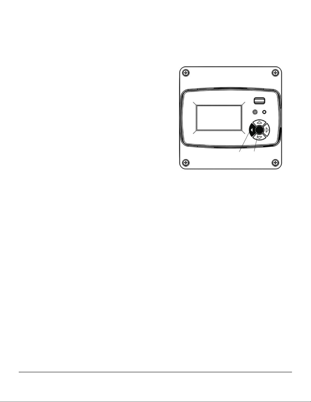
P6 - Reset notification timer
Depress the center button and left button together
for 5 seconds to reset the notification timer
(Figure P6)
Left Center
Figure P6
P5 - Saving your information
Once you have programmed the service
notification screen to your liking, simply remove
the memory stick. The information will be locked.
The memory stick retains the information and can
be used to program the LCD screen of any
6RDP(L) models model on your next install. Simply power up
and insert the programmed memory stick into the
USB port. It will automatically upload and save the
data to the new UV module’s memory.
Warranty Information
The RESPICAIRE limited warranty covers any defect in materials or workmanship for a period of five years in residential applications. The warranty
period commences on the purchase date of the product. The warranty does not cover any damage from misuse, neglect or abuse. To make a warranty
claim contact the original installing contractor or Respicaire directly with a copy of an original sales receipt or other evidence of the date of purchase.
Respicaire is a trademark of the TFI Company Inc. The limited warranty for all comercial applications is one yaer.
Note: In some areas air cleaners and Ultra Violet purifiers are covered by medical insurance and may be tax deductible if prescribed by a Physician.
This will vary according to local legislation. The following information is usually required.
Physician’s Name: _________________________________________________________________________________________
Physician’s Authorization: ___________________________________________________________________________________
_________________________________________________________________________________________________________
Prescription: _______________________________________________________________________________________________
Patient Name: _____________________________________________________________________________________________
Address: _________________________________________________________________________________________________
City: _____________________________________ State/Province: _________________________________________________
Zip /Postal Code: ________________________________
6RDOXY-inst5
This manual suits for next models
5
Table of contents