RESQTEC G Series Product information sheet

USER MANUAL
G-SERIES CUTTERS
EN | Original RESQTEC user manual
WWW.RESQTEC.COM

USER MANUAL CUTTER G-SERIES
RESQTEC USER MANUAL G-SERIES (DM065K09)2
1. INTRODUCTION: SAFETY FIRST 03
1.1. Safety messages 03
1.2. General safety information 03
1.3. Safety information 04
1.4. Product identication 04
1.5. Applicable types 05
2. PRODUCT SUMMARY 06
2.1. Introduction 06
2.2. Product description 06
2.3. Component identication 06
2.3.1 G2 06
2.3.2 G4a/w, G6a/c/w, G8c/w 07
3. PRODUCT RANGE 08
3.1. Products & Accessories 08
4. GENERAL OPERATING INSTRUCTIONS 10
4.1. Initial use 10
4.2. Preparation before use 10
4.3. Operation 11
4.4. Optimized 350 bar 11
4.5. Quick action couplers 12
4.6. Connecting the Resqtec NEO1 coupler 12
4.7. Disconnecting the Resqtec NEO1 coupler 13
4.8. Connecting the Resqtec STD coupler 14
4.9. Disconnecting the Resqtec STD coupler 14
4.10. Using the pressure release 15
4.11. Operating the product 16
5. SPECIFICATIONS 17
5.1. Technical specications 17
5.1.1 SI-system data 17
5.1.2 Imperial system data 20
5.1.3 Cutting capabilities 23
5.2. Technical drawings 24
5.2.1 Si-System Data 24
5.2.2 Imperial System Data 26
6. MAINTENANCE & STORAGE 28
6.1. Maintenance after use 28
6.2. Regular maintenance 30
6.3. Annual maintenance 31
6.4. Recommended storage 31
6.5. Decommissioning & recycling 31
7. WARNINGS & LIMITATIONS 32
7.1. General instruction 32
7.2. Twisting of blades 32
8. TROUBLESHOOTING 33
9. WARRANTY 34
10. DISCLOSURE 35
11. CONTACT 36

USER MANUAL CUTTER G-SERIES
RESQTEC USER MANUAL G-SERIES (DM065K09)3
1. INTRODUCTION: SAFETY FIRST
1.1. SAFETY MESSAGES
This manual contains safety messages. They point out potential hazards that could hurt you or others around you as well as damage the
equipment in use. These messages should therefore be read carefully and understood. They are highlighted by the safety alert symbol
as shown on the left:
The potential hazards are explained as to what could happen and how to avoid or reduce the chance for injury or damage.
Important information has been highlighted as well. To point out this information, a light bulb icon is used. It brings topics to your
attention that could, for example, facilitate maintenance or to clarify when it is advisable to consult your distributor/supplier.
1.2 GENERAL SAFETY INFORMATION
The Resqtec equipment is designed to provide safe operation. All users should read and be thoroughly familiar with the operating instructions
and safety precautions stated in this manual. Operator safety depends on users being properly trained by the Authority having jurisdiction and
using the equipment for its intended purposes only. The following safety precautions must be observed at all times:
UNTRAINED USE OF RESQTEC EQUIPMENT AND ITS ACCESSORIES MAY RESULT IN VERY DANGEROUS AND
POTENTIALLY HARMFUL SITUATIONS. DO NOT ATTEMPT!
• Resqtec equipment must only be operated by people authorized and qualied by the Authority having jurisdiction.
• Be aware that this is not an all-encompassing training manual. This manual is meant as a reference-guide for working with this
specic piece of equipment, and the user should already be trained in and qualied for using rescue equipment.
• Suitable protective equipment must be worn as directed by the Authority having jurisdiction. At a minimum, this should include
gloves, helmet, eye protection and body protection — such as turnout gear.
• Prior to use, inspect all components for any signs of damage or fraying. Do not use damaged equipment.
• Stay alert. Do not operate the system when tired.
• Use only Resqtec authorized service parts.
• This equipment should only be used with accessories approved by Resqtec. Use of unauthorized accessories can result
in unpredictable and unreliable produkt operation and is therefore prohibited.

USER MANUAL CUTTER G-SERIES
RESQTEC USER MANUAL G-SERIES (DM065K09)4
1.3. SAFETY INFORMATION
Before using the equipment and its related products and accessories, conduct an overall size-up of the intended use and safeguard against
potential hazards before installing the product. Read and understand this manual before using the equipment.
The WARNING and SAFETY labels on the product alert the user to special hazards inherent with its use. Should they
become damaged or unreadable, contact the manufacturer to obtain a replacement.
BEFORE INSTALLING THE PRODUCT, BE AWARE OF THE FOLLOWING:
• Make sure that no kink will form in any of the hoses during use. Make sure that the hose provides a free ow at all times.
Failing to do so may result in damage to the hose assembly and malfunction of your Resqtec system.
• Make sure no one on site is in danger or might get, when using Resqtec equipment. Be aware of your surroundings,
the situation you and the people around you are in, and what the consequences of the use of the Resqtec system are.
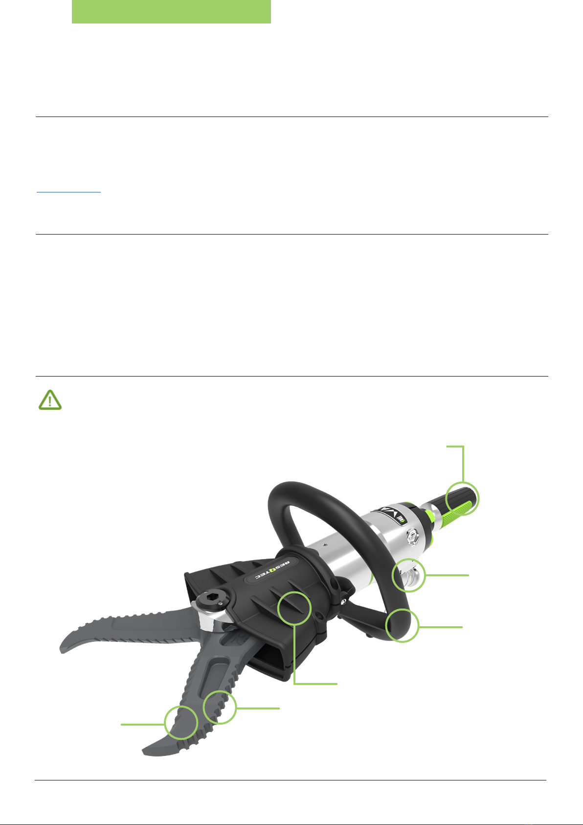
• When in use hold the product by the handles.
• NEVER, when in use, hold the product by any of its moving parts. Doing so can result in serious injury.
• NEVER, when in use, place your hands or any other body parts between the moving parts and a (stationary) object.
Doing so can result in serious personal injury.
• When using the Resqtec product always ensure that the object is stable or stabilized by proper cribbing and/or shoring methods.
• NEVER pull a Resqtec product towards you by the hoses. Pick up the product by the handles instead, as intended.
• NEVER pull a hose to try to untangle it or to free a hose from an obstacle. Always direct your full attention to the problem;
clear the hose from the obstacle or untangle the hose before proceeding.
1.4. PRODUCT IDENTIFICATION
Product identication is to make sure that this manual comes with a specic product and that this manual should always be available as a
reference guide to that equipment. It is mandatory that this manual is not separated from the product specied below during its service life.
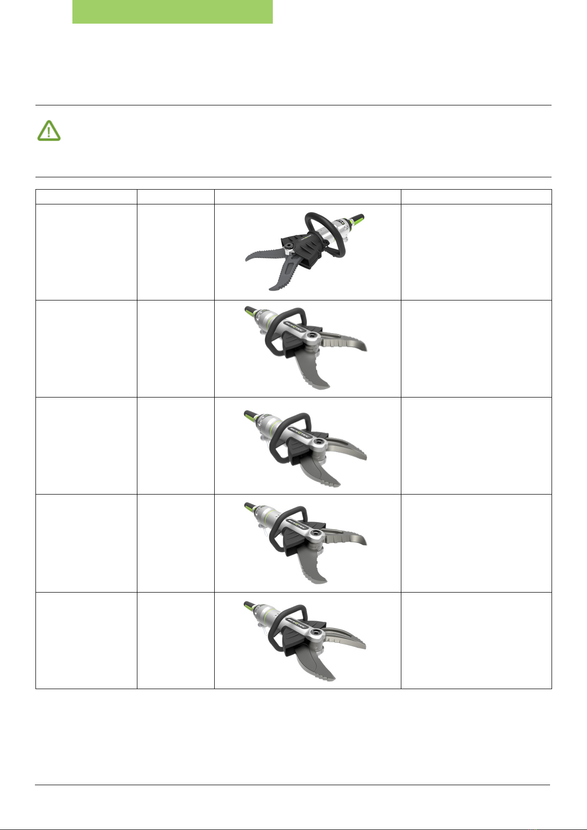
This manual comes with Resqtec product type:
GWith serial number: Hydraulic uid used in product: RESQTEC OPTI-GREEN HF-15 BIODEGRADABLE
RESQTEC OPTI-GREEN HF-15 BIODEGRADABLE
SKYDROL (PHOSPHATE ESTER MCS 2361)
Distributor/Supplier information:
IMAGES AS DISPLAYED IN THIS MANUAL MAY DIVERGE FROM ACTUAL PRODUCT APPEARANCE.

USER MANUAL CUTTER G-SERIES
RESQTEC USER MANUAL G-SERIES (DM065K09)5
1.5 APPLICABLE TYPES
This manual covers the following product types:
Article number Item description
4120.0000.** G2
5141.0100.** G4a
5143.0200.** G4w
5161.0100.** G6a
5162.0100.** G6c
5163.0300.** G6w
5182.0100.** G8c
5183.0100.** G8c

USER MANUAL CUTTER G-SERIES
RESQTEC USER MANUAL G-SERIES (DM065K09)6
2. PRODUCT SUMMARY
2.1 INTRODUCTION
Thank you for choosing Resqtec. We are condent that we live up to your expectations. This manual has been compiled carefully to supply the
reader with all the necessary information. Read all the instructions before using the product to assure safe and optimal use of the product.
These instructions contain aspects relevant to safe and optimal use of the product.
The product has been manufactured by Resqtec Zumro. For addresses, please refer to the last page of this manual or to our internet site at
www.resqtec.com.
2.2 PRODUCT DESCRIPTION
The cutters have been designed and engineered to assist reghters, USAR-teams and other rescue workers with the various rescue
applications they encounter. We are condent that the design of this product will enable those working in these environments to not only
negotiate the obstacles they encounter, but to perform their work more safely.
The cutters are double-acting hydraulic products designed to be driven by a Resqtec hydraulic pump. The products operate with hydraulic oil
and 350bar/5,075 PSI allowable pressure. To see which specic hydraulic uid your product uses, see chapter 1.4 of this manual, or look on the
product label. Further information regarding the hydraulic uid in your system can be found in the “Material Safety Data Sheet” or “MSDS”
which came with your product.
2.3 COMPONENT IDENTIFICATION
IMAGES AS DISPLAYED IN THIS MANUAL MAY DIVERGE FROM ACTUAL PRODUCT APPEARANCE.
2.3.1 G2
CUTTER BLADE
CARRYING HANDLE
PROTECTION COVERS
OUTER BLADE GRIP
CONTROL HANDLE
NEO1 (MALE) COUPLER

USER MANUAL CUTTER G-SERIES
RESQTEC USER MANUAL G-SERIES (DM065K09)7
2.3.2 G4a/w, G6a/c/w, G8c/w
CUTTER BLADE
CARRYING HANDLE
PROTECTION COVERS
SPREADING TEETH
CONTROL HANDLE
NEO1 (MALE) COUPLER

USER MANUAL CUTTER G-SERIES
RESQTEC USER MANUAL G-SERIES (DM065K09)8
3. PRODUCT RANGE
IMAGES AS DISPLAYED IN THIS MANUAL MAY DIVERGE FROM ACTUAL PRODUCT APPEARANCE.
3.1 PRODUCTS & ACCESSORIES
Article number Item description Picture Usage & Restrictions
4120.0000.** G2
5141.0100.** G4a
5143.0200.** G4w
5161.0100.** G6a
5162.0100.** G6c

USER MANUAL CUTTER G-SERIES
RESQTEC USER MANUAL G-SERIES (DM065K09)9
Article number Item description Picture Usage & Restrictions
5163.0300.** G6w
5182.0100.** G8c
5183.0100.** G8w

USER MANUAL CUTTER G-SERIES
RESQTEC USER MANUAL G-SERIES (DM065K09)10
4. GENERAL OPERATING INSTRUCTIONS
IMAGES AS DISPLAYED IN THIS MANUAL MAY DIVERGE FROM ACTUAL PRODUCT APPEARANCE.
4.1 INITIAL USE
When receiving your equipment check for any sign of damage to the box, and report it to your distributor/supplier as damage could have
occurred during shipping. Unpack in upright position and check the product for damage. To make sure the product conforms to your
specications, check the product details on the label.
CHECK THE EQUIPMENT FOR EXTERNAL DAMAGE. NOTIFY YOUR DISTRIBUTOR/SUPPLIER IMMEDIATELY IF ANY
DAMAGE IS FOUND. DO NOT USE DAMAGED EQUIPMENT UNDER ANY CIRCUMSTANCE!
In general we distinguish a couple of different types of operations;
• Connecting the Resqtec NEO1 coupler
• Disconnecting the Resqtec NEO1 coupler
• Connecting the Resqtec STD coupler
• Disconnecting the Resqtec STD coupler
• Using the pressure release
• Operating the product
4.2 PREPARATION BEFORE USE
• Check the blades of the product. Do not use if they exhibit
major damage and/or do not function as intended.
• See chapter 6 for further information.
• Check the operation of the dead-man’s valve.
It should return to its neutral position when released.
• See chapter 6 for further information.
• Check the carrying handle. It must be rmly xed. • See chapter 6 for further information.
• Check the protection covers. They must be present
and undamaged.
• See chapter 6 for further information.

USER MANUAL CUTTER G-SERIES
RESQTEC USER MANUAL G-SERIES (DM065K09)11
4.3 OPERATION
The product is operated by the dead-man’s control handle:
• Rotating the control handle leftward will make the blades open up.
• Rotating the control handle rightward will make the blades close.
To keep extending or retracting keep the control handle rotated. Adjust the speed by rotating more or less.
By releasing the control handle the dead-man’s control will make the control handle return to neutral position.
The pressure in the product will remain due to the DIN-valve. The blades cannot be moved by external forces.
4.4 OPTIMIZED 350 BAR
Resqtec products operate at 350bar/5,075 PSI allowable pressure (Optimized 350 bar), which allows a smooth and more controlled operation. To
support interoperability, Resqtec can also provide means to connect the products to other brands’ system components. Contact your distributor/
supplier for information about parts (couplers e.g.) to make your equipment ready for interoperability.
ALWAYS BE AWARE THAT TO CONNECT A RESQTEC PRODUCT TO ANY PUMP, THE SAME HYDRAULIC FLUID
AND COUPLERS NEED TO BE USED.
Your product can be supplied with the requested coupler(s) or can be changed in a later stadium by your distributor/
supplier. It is also possible to purchase an adaptor kit between different connectors. Contact your distributor/supplier
if you want to connect to another pump and change the uid and/or coupler if necessary.
In this manual the Resqtec NEO1 couplers and the Resqtec STD couplers are described; follow the instructions of your current couplers only.
NEUTRAL
RIGHTLEFT

USER MANUAL CUTTER G-SERIES
RESQTEC USER MANUAL G-SERIES (DM065K09)12
4.5 QUICK ACTION COUPLERS
The standard product is equipped with NEO1 quick action automatic by-pass couplers. This makes it possible to connect and disconnect both
pressure and return in one simple motion. It also allows you to connect and disconnect under full pump free ow pressure. If your product is
supplied with STD couplers, the connectors for pressure and return are separated. Make sure the pump is switched to neutral when connecting
or disconnecting these STD couplers. If your product is modied on your request with other couplers, please also refer to that coupler supplier’s
manual for proper additional instruction.
BEFORE USAGE, MAKE SURE TO CHECK THE FOLLOWING
4.6 CONNECTING THE RESQTEC NEO1 COUPLER
Make sure the dust caps are removed from both the coupler
(male & female):
• Female dust cap releases when female coupler is released
(rotate and pull back).
• Male dust cap releases by simply pulling it.
Align the NEO1 female coupler located on the hose with the
NEO1 male coupler located on the product.
Push to connect in one swift motion (if difcult to connect refer
to chapter 4.10 for pressure release).
2
3
1
• Make sure connectors (and pins) are clean to ensure proper operation.
• Pull both couplers to check whether the couplers are properly connected.
• If couplers do not have auto lock mechanism on the product, rotate collar of female coupler to lock and prevent accidental release.
• Unroll hose reels to their full extend. Make sure that no pressure is applied before unrolling.

USER MANUAL CUTTER G-SERIES
RESQTEC USER MANUAL G-SERIES (DM065K09)13
Rotate the NEO1 female coupler unlock ring in the direction of the arrow
and pull backwards.
Make sure the control handle of the tool is not engaged
when disconnecting (neutral position).
The NEO1 female coupler on the hose ejects automatically.
A few drops of uid discharge is normal.
Make sure the dust caps are placed back on both couplers
(male & female).
4.7 DISCONNECTING THE RESQTEC NEO1 COUPLER
2
3
1

USER MANUAL CUTTER G-SERIES
RESQTEC USER MANUAL G-SERIES (DM065K09)14
Remove the dust caps from the couplers.
Align the STD coupler and push the male and female part rmly
into each other.
4.8 CONNECTING THE RESQTEC STD COUPLER
Rotate the collar on the STD coupler until the cutout on the collar is in
front of the ball. Then push the collar towards the female connector.
The male connector will be ejected
automatically.
Place the dust caps on both couplers.
Check whether the pump relief valve is in its neutral/release pressure relief position (with exception of NEO1).
NEVER TRY TO CONNECT THE COUPLERS IF THE PUMP IS SWITCHED TO OPERATION.
2
3
4.9 DISCONNECTING THE RESQTEC STD COUPLER
1
2
1

USER MANUAL CUTTER G-SERIES
RESQTEC USER MANUAL G-SERIES (DM065K09)15
4.10 USING THE PRESSURE RELEASE
In some situations, pressure may build-up in the product, making it difcult to connect.
This pressure can easily be released.
For STD couplers a separate pressure release tool is available. Contact your distributor/supplier for details.
Take the NEO1 male dust cap and turn it around. The opposite side of
the dust cap contains the pressure release activator. Align the backside
of the NEO1 male dust cap with the NEO1 male coupler.
Push the pressure release activator pin, located on the backside of the
NEO1 male dust cap, onto the NEO1 male coupler which contains the
pressure release valve.
NOTE THAT A SLIGHT AMOUNT OF HYDRAULIC FLUID
WILL EJECT AT THIS POINT!
MAKE SURE TO WEAR PROTECTIVE CLOTHING.
1
2

USER MANUAL CUTTER G-SERIES
RESQTEC USER MANUAL G-SERIES (DM065K09)16
4.11 OPERATING THE PRODUCT
BEFORE STORING THE PRODUCT IT IS RECOMMENDED TO DEPRESSURIZE THE CYLINDER. TO DO THIS,
OPEN THE BLADES TO THE POINT WHERE ONLY THE TIPS TOUCH EACH OTHER.
Connect a hydraulic hose to the product
and power unit.
See chapter 4.6. or 4.8
Start the hydraulic power unit
(and open the valve).
Please refer to the power unit’s user manual for
additional information.
Rotate the control handle leftwards to open
the blades.Keep the handle leftwards.
Rotate the control handle rightwards to close
the blades. Keep the handle rightwards.
2
1
4
3

USER MANUAL CUTTER G-SERIES
RESQTEC USER MANUAL G-SERIES (DM065K09)17
5. SPECIFICATIONS
The hydraulic cutters G-series have been engineered and tested to be able to cut through a wide variety of steel and
other materials, whether it is in the form of a prole or an actual post. An overview of the capacities and other
specications is given below.
5.1 TECHNICAL SPECIFICATIONS
5.1.1 SI-SYSTEM DATA
G2 CUTTER NEO1-coupler STD-coupler
Allowable operating pressure Optimized 350 bar
Tailhose safety factor - 8:1 (2,800 bar)
Dimensions (L x W x H) 644 x 224 x 246 mm
Operational weight 9.0 kg (±0.2kg) 9.6 kg (±0.2kg)
Max. cutting opening 180 mm
Max. cutting opening reach 114mm
Max. cutting force 340 kN / 34.7 ton
EN 13204 BC152F-10
NFPA 1936 A5 B6 C6 D7 E6
G4a CUTTER NEO1-coupler STD-coupler
Nominal pressure Optimized 350 bar
Tailhose safety factor - 8:1 (2.800 bar)
Dimensions (L x W x H) 717 x 236 x 221 mm
Operational weight 11.0 kg (±0.2kg) 12.2 kg (±0.2kg)
Max. cutting opening 215 mm
Reach 145 mm
Max. cutting force* 809 kN / 82.5 ton
EN 13204 cutting capability 1I 2H 3H 4J 5I (H-class)
NFPA 1936 cutting capability A6 B7 C6 D7 E6
Round bar capability (S235 acc. to EN 13204) 36 mm
EN 13204 classication CC 200H-11.0 CC 200H-12.2
G4w CUTTER NEO1-coupler STD-coupler
Nominal pressure Optimized 350 bar
Tailhose safety factor - 8:1 (2.800 bar)
Dimensions (L x W x H) 673 x 236 x 221 mm
Operational weight 10.3 kg (±0.2kg) 11.5 kg (±0.2kg)
Max. cutting opening 154 mm
Reach 127 mm
Max. cutting force* 623 kN / 63.5 ton
EN 13204 cutting capability 1H 2G 3G 4F 5G (F-class)
NFPA 1936 cutting capability A6 B6 C6 D7 E6
Round bar capability (S235 acc. to EN 13204) 30mm
EN 13204 classication BC 154F-10.3 BC 154F-11.5

USER MANUAL CUTTER G-SERIES
RESQTEC USER MANUAL G-SERIES (DM065K09)18
G6a CUTTER NEO1-coupler STD-coupler
Nominal pressure Optimized 350 bar
Tailhose safety factor - 8:1 (2.800 bar)
Dimensions (L x W x H) 799 x 268 x 235 mm
Operational weight 14,9 kg (±0.2 kg) 16,1 kg (±0.2 kg)
Max. cutting opening 271 mm
Reach 141 mm
Max. cutting force* 1.350 kN / 137.7 ton
EN 13204 cutting capability 1J 2J 3I 4K 5K (I-class)
NFPA 1936 cutting capability A7 B8 C7 D9 E8
Round bar capability (S235 acc. to EN 13204) 40mm
EN 13204 classication CC 212I-14.9 CC 212I-16.1
G6c CUTTER NEO1-coupler STD-coupler
Nominal pressure Optimized 350 bar
Tailhose safety factor - 8:1 (2.800 bar)
Dimensions (L x W x H) 777 x 268 x 235 mm
Operational weight 14,7 kg (±0.2 kg) 15,9 kg (±0.2 kg)
Max. cutting opening 200 mm
Reach 150 mm
Max. cutting force* 1.344 kN / 137 ton
EN 13204 cutting capability 1I 2K 3H 4J 5J (H-class)
NFPA 1936 cutting capability A7 B8 C6 D7 E9
Round bar capability (S235 acc. to EN 13204) 38mm
EN 13204 classication CC 200H-14.7 CC 200H-15.9
G6w CUTTER NEO1-coupler STD-coupler
Nominal pressure Optimized 350 bar
Tailhose safety factor - 8:1 (2.800 bar)
Dimensions (L x W x H) 761 x 268 x 235 mm
Operational weight 14,3 kg (±0.2 kg) 15,5 kg (±0.2 kg)
Max. cutting opening 187 mm
Reach 149 mm
Max. cutting force* 1.283 kN / 131 ton
EN 13204 cutting capability 1I 2K 3I 4J 5J (I-class)
NFPA 1936 cutting capability A7 B8 C6 D7 E9
Round bar capability (S235 acc. to EN 13204) 38mm
EN 13204 classication BC 187I-14.3 BC 187I-15.5

USER MANUAL CUTTER G-SERIES
RESQTEC USER MANUAL G-SERIES (DM065K09)19
G8c CUTTER NEO1-coupler STD-coupler
Nominal pressure Optimized 350 bar
Tailhose safety factor - 8:1 (2,800 bar)
Dimensions (L x W x H) 891 x 312 x 238 mm
Operational weight 20.5 kg (±0.2 kg) 21.7 kg (±0.2 kg)
Max. cutting opening 203 mm
Reach 155 mm
Max. cutting force* 1,541 kN / 157 ton
EN 13204 cutting capability 1K 2K 3K 4K 5K (K-class)
NFPA 1936 cutting capability A9 B9 C9 D9 E9
Round bar capability (S235 acc. to EN 13204) 48 mm
EN 13204 classication CC 203K-20.5 CC 203K-21.7
G8w CUTTER NEO1-coupler STD-coupler
Nominal pressure Optimized 350 bar
Tailhose safety factor - 8:1 (2,800 bar)
Dimensions (L x W x H) 872 x 312 x 238 mm
Operational weight 20.0 kg (±0.2 kg) 21.2 kg (±0.2 kg)
Max. cutting opening 200 mm
Reach 150 mm
Max. cutting force* 1,518 kN / 155 ton
EN 13204 cutting capability 1J 2K 3K 4K 5K (J-class)
NFPA 1936 cutting capability A8 B9 C8 D9 E9
Round bar capability (S235 acc. to EN 13204) 43 mm
EN 13204 classication CC 200J-20.0 CC 200J-21.2

USER MANUAL CUTTER G-SERIES
RESQTEC USER MANUAL G-SERIES (DM065K09)20
5.1.2 IMPERIAL SYSTEM DATA
G2 CUTTER NEO1-coupler STD-coupler
Allowable operating pressure 5,075 PSI
Tailhose safety factor - 8:1 (40,600 PSI)
Dimensions (L x W x H) 25 3/8’’ x 8 3/4’’ x 9 3/4’’
Operational weight 19.8 lbs (±0.4 lbs) 21.2 lbs (±0.4 lbs)
Max. cutting opening 7 1/8’’
Max. cutting opening reach 4 1/2’’
Max. cutting force 340 kN / 76,435 lbf
EN 13204 BC152F-10
NFPA 1936 A5 B6 C6 D7 E6
G4a CUTTER NEO1-coupler STD-coupler
Nominal pressure Optimized 5,075 PSI
Tailhose safety factor - 8:1 (40,600 PSI)
Dimensions (L x W x H) 28 1/4’’ x 9 1/4’’ x 8 3/4’’
Operational weight 24.3 lbs (±0.4 lbs) 26.9 lbs (±0.4 lbs)
Max. cutting opening 8 1/2’’
Reach 5 3/4’’
Max. cutting force* 809 kN / 181,870 lbf
EN 13204 cutting capability 1I 2H 3H 4J 5I (H-class)
NFPA 1936 cutting capability A6 B7 C6 D7 E6
Round bar capability (S235 acc. to EN 13204) 1 27/64”
EN 13204 classication CC200I-11.0 CC200I-12.2
G4w CUTTER NEO1-coupler STD-coupler
Nominal pressure Optimized 5,075 PSI
Tailhose safety factor - 8:1 (40,600 PSI)
Dimensions (L x W x H) 26 1/2’’ x 9 1/4’’ x 8 3/4’’
Operational weight 22.7 lbs (±0.4 lbs) 25.4 lbs (±0.4 lbs)
Max. cutting opening 6’’
Reach 5’’
Max. cutting force* 623 kN / 140,056 lbf
EN 13204 cutting capability 1H 2G 3G 4F 5G (F-class)
NFPA 1936 cutting capability A6 B6 C6 D7 E6
Round bar capability (S235 acc. to EN 13204) 1 3/16”
EN 13204 classication BC 154F-10.3 BC 154F-11.5
Table of contents
Other RESQTEC Cutter manuals