p 4
Eraser Company Inc. • Syracuse, NY USA • Ph: 315-454-3237 • info@eraser.com • www.eraser.com • Fax 315-454-3090
ENSURE PROPER ALIGNMENT OF MOVING
PARTS Check for any binding of moving parts,
breakage of parts, and any other condition(s) that
may affect operation. Any damaged part(s) should
be properly repaired or replaced prior to any
continued use of the machine.
ONLY ALLOW TRAINED AND QUALIFIED
PERSONNEL TO OPERATE UNIT Always keep
these instructions within reach of the machine.
USE RECOMMENDED ACCESSORIES ONLY
Consult this operating manual for recommended
accessories. Use only parts supplied by The Eraser
Company, Inc. Use of improper accessories will void
Eraser’s warranty and may increase risk of injury.
ALL REPAIRS SHOULD BE PERFORMED BY AN
ERASER COMPANY REPRESENTATIVE ONLY
Unauthorized disassembly of machines will void
Eraser’s warranty.
WHEN USING MACHINERY, ALL SAFETY
PRECAUTIONS – INCLUDING, BUT NOT LIMITED TO,
THOSE LISTED ABOVE - SHOULD BE FOLLOWED
TO REDUCE THE RISKS OF FIRE, ELECTRIC SHOCK,
AND PERSONAL INJURY, AND DEATH.
IMPORTANT: NO LIABILITY WILL BE INCURRED
BY THE ERASER CO. FOR INJURY, DEATH, OR
PROPERTY DAMAGE CAUSED BY A PRODUCT
WHICH HAS BEEN SET UP, OPERATED, AND/OR
INSTALLED CONTRARY TO ERASER’S WRITTEN
OPERATING MANUAL, OR WHICH HAS BEEN
SUBJECTED TO MISUSE, NEGLIGENCE, OR
ACCIDENT, OR WHICH HAS BEEN REPAIRED
OR ALTERED BY ANYONE OTHER THAN THE
ERASER COMPANY, OR WHICH HAS BEEN
USED IN A MANNER OR FOR A PURPOSE FOR
WHICH THE PRODUCT WAS NOT DESIGNED.
SET-UP: Check your shipment to be sure all items
listed under the parts section are in the box. If
anything is missing, please let us know immediately.
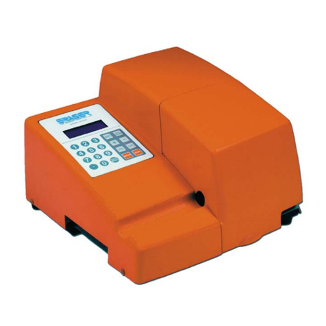
Place the model WC601D on a sturdy workbench.
A material collection bin can be placed on the right
side of the unit, beneath the clear guard.
NOTE: It is possible for the WC601D to be controlled
by an external device or process, by using the DB9
connector located on the rear panel of the unit. Contact
a sales representative for more details.
The WC601D may also be used with a tensioning
dereeler or an automatic pre-feed system. Use
of the Model DE700 Compensating Dereeler
is recommended. This device will improve the
accuracy and/or productivity of the WC601D. If
using the DE700 (or any other dereeling system),
place the dereeler to the left side of the WC601D,
approximately 24” (for elastic materials the distance
may be reduced) from the entrance bushing in a
straight line and align the exit pulley of the dereeler
with the entrance bushing of the WC601D. If using
the DE700, refer to the operating manual for further
set up details.
First, remove the unit’s front cover/guard by
loosening the (2) thumb screws located on the front
and top of the front cover. Referring to the drawing
on page 16, locate the blade stop adjusting screw
on the cutting head.
Prior to shipment, the blade stop adjusting screw
has been set to lock the blade holder in the open
position, to secure it during transport. Prior to
bushing installation (see below) loosen the locking
set screw (which secures the blade stop screw),
then back the blade stop screw away from the blade
holder mechanism.
BUSHING INSTALLATION:(Refer to the drawing on page 15)
The WC601D requires one (1) set of custom
bushings. A bushing set consists of one (1) of each
of the following: the entrance bushing (7/8” long w/
hub); the head (middle) bushing (2 5/8” long); & the
exit bushing (1 3/8” long), for a total of 3 bushings.
If different sizes of material are going to be cut,
additional bushing sets may be ordered.
First install the head bushing. Lift the clear guard on
the right side of the unit and insert the ID-chamfered
end of the head bushing into the hole under the
clear guard. Slide the head bushing completely past
the blade on the cutting head.
Manually actuate the blade holder (see Set-up,
above) and slide the head bushing back toward the
blade until the clearance between the bushing &
the blade is approximately 1/32”. Tighten the head
bushing in place, then lift the clear guard and insert
the exit bushing until the bushing is approximately
1/32” from the opposite side of the blade from the
MODEL WC601D AUTOMATIC TUBING CUTTER
