TRC 1000 Series User manual

Service Manual for 1000
Series Strip cutters
Rev 1.1 6/6/22

2
Table of Contents
Safety Information for TRC-1000 Strip Cutters .................................................................................... 4
Specifications....................................................................................................................................... 5
Model Identification............................................................................................................................ 6
Nomenclature ..................................................................................................................................... 7
Setting Up and Using your new TRC 1000 Series Strip Cutters .......................................................... 8
Model HC4 and HC7 Setup............................................................................................................. 8
Start Up Procedures ......................................................................................................................... 8
Keyboard Commands................................................................................................................... 10
Entering A program ....................................................................................................................... 10
Feed Rate ................................................................................................................................... 10
Length ......................................................................................................................................... 10
Cut Time ...................................................................................................................................... 11
How Many................................................................................................................................... 11
Operating Screen....................................................................................................................... 12
Stopping the Machine................................................................................................................... 12
Model CC4 and CC7 Setup ............................................................................................................. 12
Start Up Procedures........................................................................................................................... 13
Keyboard Commands................................................................................................................... 13
Entering a Program........................................................................................................................ 13
Feed Rate ................................................................................................................................... 13
Length ......................................................................................................................................... 14
Cut Time ...................................................................................................................................... 15
How Many................................................................................................................................... 15
Stopping the Machine ............................................................................................................... 15
Model HC4-FS Setup.......................................................................................................................... 16
Start Up Procedures........................................................................................................................... 16
Periodic Maintenance and Repairs................................................................................................. 16
Tools needed:................................................................................................................................. 17
Linear Shafts/Bearings and Air Cylinder shafts:............................................................................ 18
Drive and Tension Rollers ............................................................................................................... 18
Springs:............................................................................................................................................ 20
Drive Belt and Pulleys:.................................................................................................................... 21
Cutting Blades and Cutting Plates ............................................................................................... 22

3
Hot Knife Cutters: ........................................................................................................................... 22
Hot Knife Blade Adjustment .......................................................................................................... 24
Cold Knife Cutters: ......................................................................................................................... 25
Cold Cutter Blade Adjustment ..................................................................................................... 25
Replacing an air cylinder .............................................................................................................. 26
Adjusting the Air Valve .................................................................................................................. 27
Feed Roller Replacement ............................................................................................................. 29
Top Roller Replacement................................................................................................................ 30
Spring Tension Adjustment ............................................................................................................ 30
Drive Belt adjustment..................................................................................................................... 31
Drive Motor Replacement ............................................................................................................ 32
Thermostat, heater cord and heating element testing.............................................................. 33
Heating Element Replacement.................................................................................................... 34
Integrated Cutoff Switch Installation Instructions ........................................................................ 36
Adjusting LCD Contrast ................................................................................................................. 39
Control Panel Calibration.............................................................................................................. 40
Calibration Method 1................................................................................................................. 40
Calibration Method 2................................................................................................................. 40
Replacing Main Fuse ..................................................................................................................... 41
Type 1 .......................................................................................................................................... 41
Type 2 .......................................................................................................................................... 43
Replacing Circuit Board Fuse for Drive Rollers ............................................................................. 43
Troubleshooting ................................................................................................................................. 45
Controller Troubleshooting......................................................................................................... 45
Cutter Troubleshooting .............................................................................................................. 48
Checking for Electrical problems ................................................................................................. 51
Voltage checks with Power to panel........................................................................................... 51
Circuit board removal ................................................................................................................... 52
Control cable test .......................................................................................................................... 52

4
Safety Information for TRC-1000 Strip Cutters
Congratulations on the purchase of your new TRC 1000 Strip cutter. TRC Industries has been
manufacturing and servicing the TRC 1000 series strip cutters since 1993. These cutters are
solidly built, easy to use machines that will last a lifetime with proper care and maintenance.
They are still machines however, and great care must be taken to ensure safe and satisfactory
operation. The following Safety information should be read and understood before attempting
to operate machine. Careless operation can lead to injury and downtime.
1. Make sure the outlet that supplies electricity to your TRC-1000 is properly wired,
grounded and overload protected. We recommend checking with a qualified
electrician when sizing breakers, as your individual needs may vary. The TRC 1000 series
uses less than 10 amps of current.
2. The Cutter Head and Control Panel should be placed on a sturdy table free from
wobble or other movement.
3. Care should be taken with loose fitting sleeves and long hair when around the cutting
unit's feed rollers.
4. Unit should be disconnected from the electrical and air supply before any service work
is performed.
5. Unit should be allowed to cool off for a minimum of 2 hours before any service work is
performed.
6. Only qualified personnel should be allowed to perform maintenance or repairs.
7. Unit should not be operated without air regulator.
8. Material should be removed from cutting unit when not in operation. This prevents
material from overheating, melting, or warping and contacting hot parts of the
machine.
9. Thermostat should be turned to the OFF position when not in operation. The hot knife
blade and block temperature will exceed 900 degrees F.
10. Metal tools absolutely not be used to unjam cutter or knife when unit is connected to
electricity.
11. Bare wires and connections should be immediately repaired or replaced before
operation continues.
12. Only factory recommended replacement parts should be used on the TRC-1000.

5
Specifications
Model
Weight
Dimensions
Power
Requirements
Air
Requirements
TRC 1000 4.5”
Hot cutter
14” x 7” x 14”
120VAC Single
Phase
Min. 40 PSIG
TRC 1000 7”
Hot Cutter
14” x 11” x 14”
120VAC Single
Phase
Min. 40 PSIG
TRC 1000 4.5”
Cold Cutter
14” x 7” x 14”
120VAC Single
Phase
Min 60 PSIG
TRC 1000 7”
Cold Cutter
14” x 11” x 14”
120VAC Single
Phase
Min 60 PSIG
TRC 1000 5”
Alternating
Angle Cutter
18” x 10” x 14”
120VAC Single
Phase
Min. 40 PSIG
TRC 1000
Prepuller
11” x 14” x 8”
120VAC Single
Phase
N/A
TRC 1000 Foot
Switch Cutter
18 lbs.
12” x 8.5” x 10”
120VAC Single
Phase
Min. 40PSIG
Control Panel
(All)
10” x 14” x 6”
120VAC Single
Phase
N/A
35 lbs
35 lbs
40 lbs
35 lbs
50 lbs
25 lbs
7 lbs

6
Model Identification
All the cutters in our first generation of cutting machines (spanning from 1993 until the time of
this publication) are part of the “TRC 1000 Series.” Model numbers beginning with the “HC”
designation are Hot Cutters. Models beginning with the “CC” Designation are cold cutters. The
following digits, either a “4” or a 7” identifies the machine as either a 4.5” or a 7” cutter,
respectively. The next two letters, either a “CS” or “VS” identify the controller unit as either a
Constant Speed or a Variable Speed controller.
Therefore, “TRC 1000 CC4-VS” would identify a 1000 Series Cold Cutter, 4.5” cutter, with a
Variable Speed Controller. Similarly, “TRC 1000 HC7-CS” would identify a 1000 series Hot cutter
in 7” cutting capacity with a Constant Speed Control panel.
It is worth noting that Cutter Heads can be used with either Variable Speed (VS) Controllers or
Constant Speed (CS) Control Panels.
Other Identifiers that may be used include the following:
•AA –Alternating Angle Model
•ICO –Integrated Cutoff Switch Equipped Model
•HT –High Torque Model
•MA –Marking Attachment Equipped Model
TRC Industries has produced more custom machines than we can count. If you have a
question about the specific model you have, or if you are interested in buying a machine
second hand, give us a call and we call help walk you through what features are included.

7
Nomenclature
Throughout this manual we will be referring to sides of the machine as well as its parts. The
diagrams below should be used as a reference to help the instructions in this manual easier to
understand. We will use the terms “infeed side” and “outfeed side” as well as “motor side”
throughout this manual.
Figure 1: The side view of this cold cutter is representative of the HC4, HC7, CC4, and CC7 cutters, with some minor
differences between the hot and cold cutter models. Note the side facing the reader is opposite the motor side of
the cutter.
Outfeed
side
Infeed side
Material Feed Direction
Roller
Tensioner
Handle

8
Setting Up and Using your new TRC 1000 Series Strip Cutters
Model HC4 and HC7 Setup
1. Place control panel and cutter on a flat table with the back of the control panel facing
the side of the cutter. Plug the black heater cord cable from the cutter into the control panel.
Next, connect the control panel to the cutter using the grey control cable. Plug the power
cord into the fused power receptacle on the control panel and the other end into a standard
120V single phase receptacle.
BE SURE ALL CABLES ARE SECURELY FASTENED BEFORE TURNING ON THE POWER!
2. Connect the air regulator to the cutter head via the press to lock fittings. Set the air
supply pressure at 40 PSI. If connected correctly the blade carrier should move to the up-
stroke position.
3. Set the roll stand on the infeed side of the cutter and line it up with the guides. Place
one plastic disk on the roll stand shaft, then feed webbing roll on to shaft so webbing rolls off
the top side of the roll. Place the other plastic disk on the roll stand and put the roll holder
collar lightly against the disk. tighten the thumb screw lightly. If the webbing does not turn
freely, loosen the roll holder a little.
Start Up Procedures
•While the machine is cold, adjust the guide strips to fit the webbing you are using. Do
not make it too tight as to cause drag on the webbing. The guide strips are there to
simply funnel the material towards the rollers (figure 2).

9
Figure 2: view from the infeed side of the machine, with feed guides visible.
•Turn master switch to the ON position.
•Set the temperature control knob to 3 and allow 10 - 15 min. for the knife to heat up.
The first few times the machine is heated up, the machine may emit the smell of hot oil.
This is normal.
•Feed the webbing through the guides and push it up to the feed rollers and then push
the FEED JOG button on the control panel. This will take the webbing through the feed
rollers. Take the webbing past the rollers an inch or so. You can also put the webbing
through the rollers by pushing down on the black knob and lifting the rollers and
pushing the webbing through.
Note: If your machine is equipped with the optional cutoff switch, you must feed material
under the trip rod before the guides.
NEVER ALLOW THE KNIFE TO BECOME RED HOT AS THIS MAY CAUSE THE WEBBING TO CATCH ON
FIRE.
Use just enough heat to cut the webbing. You will have to experiment with the webbing you
are using to find the exact temperature that works best.
Each cutter
comes
standard with
three sets of
guides, as
seen here.

10
Keyboard Commands
FEED JOG Allows you to manually operate the feed rollers
KNIFE JOG Allows you to manually operate the knife
RE-SET Allows you to clear the machine and start a new program
STOP Allows you to stop the machine and save all data in the memory. The STOP function
Also allows you to clear a data entry while programming –for example, if an incorrect value
was entered for length or cut time.
ENTER Allows you to enter program data
Entering A program
Feed Rate
Figure 3
When the control panel is turned on the loading screen and version number will be displayed.
The next series of prompts will be cut settings. The first prompt will be for feed rate. "FEED RATE
5-22 " (figure 3) will appear on the LCD. This will determine how fast the material will feed
through the machine, in inches. While our machines can feed up to 22 inches per second, the
speed required to run the machine successfully will largely be determined by the material
being cut. We recommend starting somewhere in the middle and working up if necessary.
Older machines may not have variable speed, in which case this prompt will be omitted. Type
in the desired speed and press ENTER.
Length
Figure 4

11
The Next prompt will be for length(figure 4). Type in the desired length and press ENTER. For
example, 15 inches will be typed in as “15”. For decimal values, use the “*” key. For example,
15.5 inches would be typed as “15*5”
Cut Time
Figure 5
Next, “Cut Time?” will appear on the LCD (figure 5). This is amount of time in seconds the blade
will stay in the down position for. The maximum time that most cutters can cut for is 2.4
seconds, but this varies depending on chip version. We recommend starting at 0.5 seconds an
increasing as necessary. A decimal can be entered by pressing the “*” key. Cut times will vary
with the thickness of the webbing and some trial and error is necessary to get the proper cut
time. 1" medium weight poly pro webbing will cut in about .75 seconds or 3/4 of a second.
How Many
Figure 6
This is the number of pieces that you want to cut (figure 6). After typing in a number and
BEFORE you push the Enter key you will want to insert the material through the feed guides,
pushing it up to the feed rollers. Press and hold the FEED JOG button until material advances
past the hot knife about 3". Press the KNIFE JOG button and cut off the webbing. This will give
you a fresh cut to start with.
Now with the correct piece count entered in press ENTER and the machine will start cutting.
When the number of pieces that were entered have been cut the machine will stop. If you
wish to run the same program again just push ENTER and it will run the same program again,
while maintain a running count of both program runs.

12
Operating Screen
Figure 7: screen during operation.
The operating screen will be displayed during operation (figure 7). The operating screen
displays the following:
Top left: Programmed Part length, in inches
Top right: Programmed cut time, in seconds
Bottom: Running total of programmed parts cut so far
Stopping the Machine
To stop the machine during operation and not lose the data you have entered, push the STOP
button and hold it down until the machine stops.
In the event of an emergency, simply turn the master power switch to the off position.
By using the STOP button, you will save the program and the count. To start the program again
just push ENTER and it will continue with the program you had entered. When you use RESET or
the master switch you will lose the program, meaning you will have to follow the prompts
again and enter the desired program values in again.
When finished with machine operations, simply turn thermostat and master switch off and
allow to cool. Remove material from machine to prevent material from melting.
Model CC4 and CC7 Setup
1. Place control panel and cutter on a flat table with the back of the control panel facing
the side of the cutter. Next, connect the control panel to the cutter using the grey control
cable. Plug the power cord into the fused power receptacle on the control panel and the
other end into a standard 120V single phase receptacle.
BE SURE ALL CABLES ARE SECURELY FASTENED BEFORE TURNING ON THE POWER!

13
2. Connect the air regulator to the cutter head via the press to lock fittings. Set the air
supply pressure at 60 PSI. If connected correctly the blade carrier should move to the up-
stroke position.
3. Set the roll stand on the infeed side of the cutter and line it up with the guides. Place
one plastic disk on the roll stand shaft, then feed webbing roll on to shaft so webbing rolls off
the top side of the roll. Place the other plastic disk on the roll stand and put the roll holder
collar lightly against the disk. tighten the thumb screw lightly. If the webbing does not turn
freely, loosen the roll holder a little.
Start Up Procedures
•Adjust the guide strips to fit the webbing you are using. Do not make it too tight as to
cause drag on the webbing. The guide strips are there to simply funnel the material
towards the rollers.
•Turn master switch to the ON position.
•Feed the webbing through the guides and push it up to the feed rollers and then push
the FEED JOG button on the control panel. This will take the webbing through the feed
rollers. Take the webbing past the rollers an inch or so. You can also put the webbing
through the rollers by pushing down on the black knob and lifting the rollers and
pushing the webbing through.
Note: If your machine is equipped with the optional cutoff switch, you must feed material
under the trip rod before the guides.
Keyboard Commands
FEED JOG Allows you to manually operate the feed rollers
KNIFE JOG Allows you to manually operate the knife
RE-SET Allows you to clear the machine and start a new program
STOP Allows you to stop the machine and save all data in the memory. The STOP function
Also allows you to clear a data entry while programming –for example, if an incorrect value
was entered for length or cut time.
ENTER Allows you to enter program data
Entering a Program
Feed Rate

14
Figure 8
When the control panel is turned on the loading screen and version number will be displayed.
The next series of prompts will be cut settings. The first prompt will be for feed rate. "FEED RATE
5-22 " will appear on the LCD. This will determine how fast the material will feed through the
machine, in inches. While our machines can feed up to 22 inches per second, the speed
required to run the machine successfully will largely be determined by the material being cut.
We recommend starting somewhere in the middle and working up if necessary. Older
machines may not have variable speed, in which case this prompt will be omitted. Type in the
desired speed and press ENTER.
Length
Figure 9
The Next prompt will be for length. Type in the desired length and press ENTER. For example, 15
inches will be typed in as “15”. For decimal values, use the “*” key. For example, 15.5 inches
would be typed as “15*5”

15
Cut Time
Figure 10
Next, “Cut Time?” will appear on the LCD. This is amount of time in seconds the blade will
cycle for. The maximum time that most cutters can cut for is 2.4 seconds, but this varies
depending on chip version. We recommend starting at 0.5 seconds an increasing as
necessary. A decimal can be entered by pressing the “*” key. Cut times will vary with the
thickness of the webbing and some trial and error is necessary to get the proper cut time.
How Many
Figure 11
This is the number of pieces that you want to cut. BEFORE you push enter on How many, you
will want to insert the material through the feed guides, pushing it up to the feed rollers. Press
and hold the FEED JOG button until material advances past the cold knife about 3". Press the
KNIFE JOG button and cut off the webbing. This will give you a fresh cut to start with.
Now with the correct piece count entered in press ENTER and the machine will start cutting.
When the number of pieces that were entered have been cut the machine will stop. If you
wish to run the same program again just push ENTER and it will run the same program again,
while maintain a running count of both program runs.
Stopping the Machine
To stop the machine during operation and not lose the data you have entered, push the STOP
button and hold it down until the machine stops.
In the event of an emergency, simply turn the master power switch to the off position.
By using the STOP button, you will save the program and the count. To start the program again
just push ENTER and it will continue with the program you had entered. When you use RESET or
the master switch you will lose the program, meaning you will have to follow the prompts
again and enter the desired program values in again.

16
When finished with machine operations, simply turn the master switch off.
Model HC4-FS Setup
1. Place cutter on a flat table.
2. Route footswitch to a safe comfortable place on the floor. Foot switch can be secured
with carpet tape or similar double-sided tape.
3. Next hook up the air regulator to your air supply and set the pressure at 40 PSI.
4. Plug the power cord into a 120V outlet.
Start Up Procedures
1. Turn master switch to ON position
2. Set the temperature control knob to 3 and allow 10 - 15 min. for the knife to heat up.
NEVER ALLOW THE KNIFE TO BECOME RED HOT AS THIS MAY CAUSE THE WEBBING TO CATCH ON
FIRE.
Use just enough heat to cut the webbing. You will have to experiment with the webbing you
are using to find the exact temperature that works best.
3. Place material across cutting plate. KEEPING HANDS CLEAR OF KNIFE!
4. When material is in desired position, with HANDS CLEAR, depress footswitch until knife
passes through material. Release the foot switch after blade has passed through material.
5. When you are through with the machine turn the Temperature control to OFF and
switch the Master Switch OFF.
Periodic Maintenance and Repairs

17
Your TRC 1000 Series Strip Cutter will last a long time with proper care and maintenance. You
will need a few simple tools to properly maintain and service your new TRC 1000 Series cutter.
Tools needed:
•SAE Allen wrenches. "T" handle and Ball driver styles are recommended. Sets typically
sold at hardware stores with wrenches from 0.050" –3/8" will be suitable.
•Combination end wrenches 1/4" - 9/16"
•Small and medium flathead screwdriver
•Small and medium phillips head screwdrivers
•3/16" Hex driver for jack screws
For advanced users or those who wish to fully diagnose, test, and repair circuitry on their
machine, the following will also be required:
•Volt/Ohm multimeter with continuity tester
•Pencil tip style soldering iron
•rosin core solder
•Wire strippers/crimpers
•Small angle cutting wire cutters
Again, not everyone who buys a TRC Industries 1000 series cutter will need the items in the
second list; those who choose to do advanced work on their machines, including circuit
board repairs should only do so if familiar with circuitry, and at their own risk.
As a note, most of the TRC-1000 series strip cutters are made of aluminum. While 6061-T6 is a
superb material for manufacturing rugged machines, it has its limitations. Use caution when
tightening screws and bolts, to avoid stripping the threaded holes. Also, due to a chemical
reaction between aluminum and steel, it is sometimes difficult to break loose screws before
removing them. We advise using penetrating oil in order to remove stuck bolts before
attempting to remove by force.
Simple lubrication and adjustment will prevent premature wear and tear. The following areas
should be carefully maintained on a regular basis:
18
Linear Shafts/Bearings and Air Cylinder shafts: keep clean of dust, lint and other
foreign substances. These points should also be lubricated periodically with a light weight oil,
such as sewing machine oil.
Drive and Tension Rollers:Remove any melted materials stuck onto rollers (figure 12), as
well as any strings or pieces of fabric wrapped around the rollers when safe to do so. Having
foreign materials stuck to your rollers will cause abnormal feed lengths. Guide boxes guides
should be moved periodically such that material feeds through the machine over different
parts of the roller. Alternating the contact point of the roller and material will help the rollers
last as long as possible and prevent wear spots from forming on the rollers.
Oil linear
bearings
here

19
Figure 12: Rollers in poor condition. Top: melted plastic stuck onto bottom roller (part AM4-7a). Bottom: Top Roller
(AM4-6a) split from heat. The heat guards on this machine were removed, and heat was left on without machine
running, leaving the roller to face the heater block on this side until the rubber degraded. The top roller can be
repaired; the bottom one cannot.
20
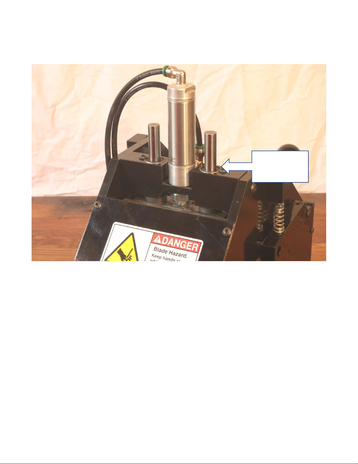
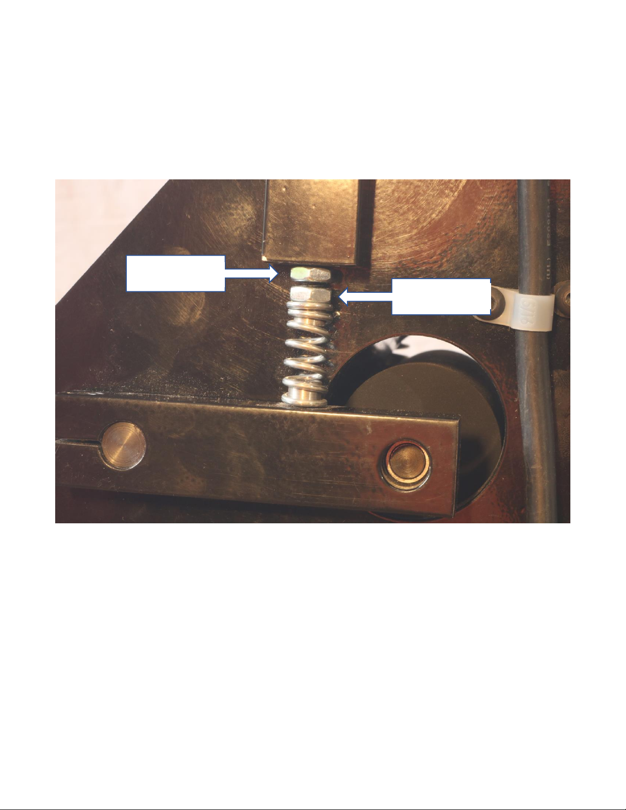
Springs: Depending on the model of TRC 1000 that you are operating, there will be springs to
tension to top roller as well as the knife blades. Proper tension on the top roller will allow
optimum grip of the material without creating excessive drag and premature bearing failure.
Too little pressure will cause material slippage. Finding the right amount of pressure will likely be
a matter of trial and error. Different types of material, as well as different thicknesses, may
require adjustment to run correctly.
Figure 13: Side view of the roller tensioner assembly
Jam Nut
Adjustment
nut
This manual suits for next models
7
Table of contents


