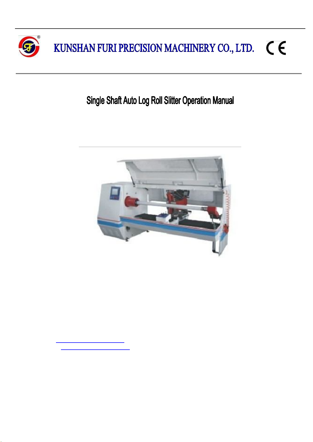
Kunshan furi precision machinery FR-1300A User manual

Model: FR-1300A, FR-1300AB, FR-1600A, FR-1600AB
Add: NO. 2258, West Chengbei Road, Bacheng Town, Kunshan, Jiangsu, China
Tel: +86-512-55183389
Fax: +86-512-55183516
E-mail: furimach@furimach.com
Website: http://www.furimach.com

Model A
CONTENTS
1. Safety instructions
1.1 safety rules ............................................................................................................ 1
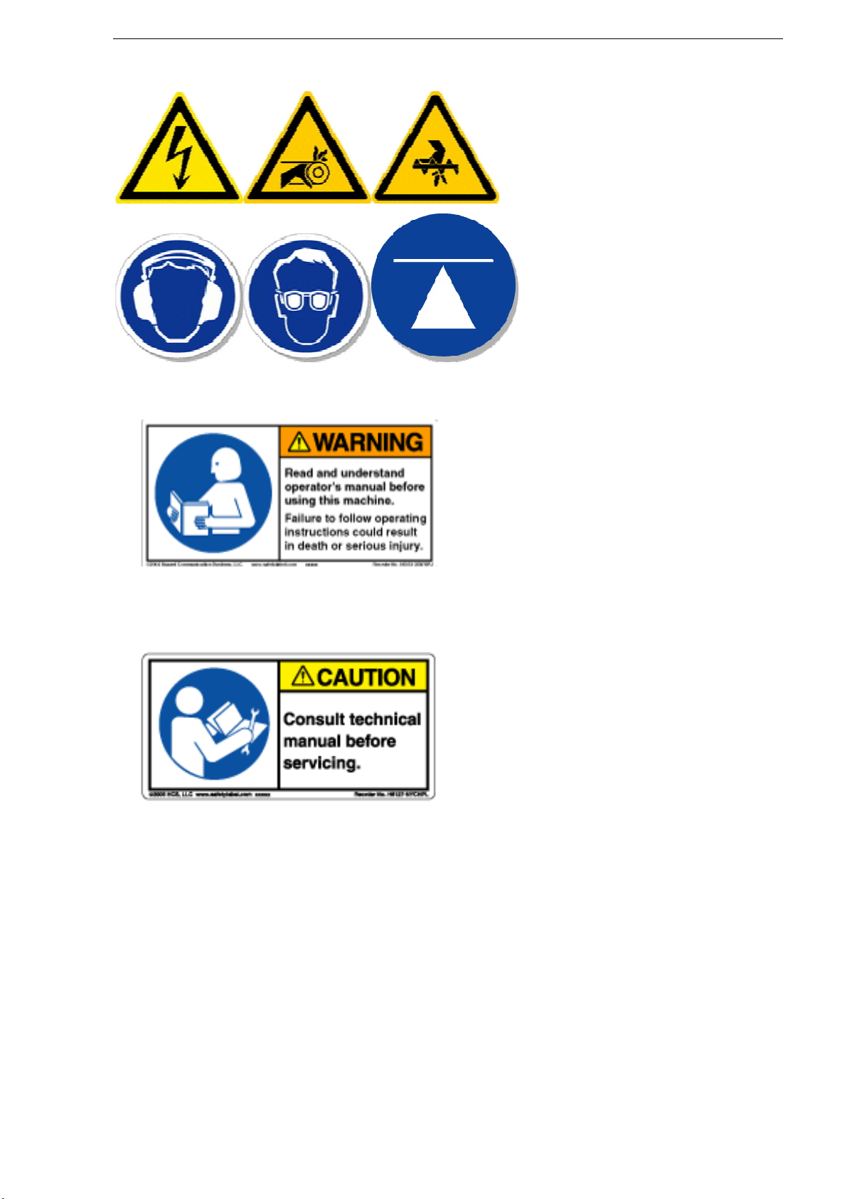
1.2 warning signs ........................................................................................................ 2
1.3 safety position ....................................................................................................... 3
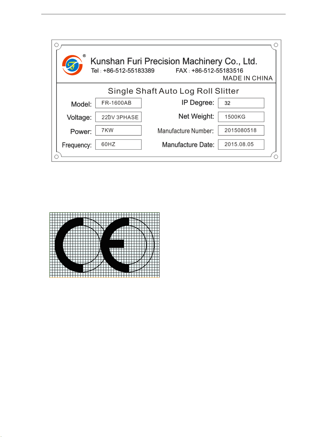
1.4 machine nameplate ................................................................................................ 4
2. Specifications
2.1 specification sheet ................................................................................................. 5
2.2 machine noise level ............................................................................................... 6
2.3 function & feature ................................................................................................. 7
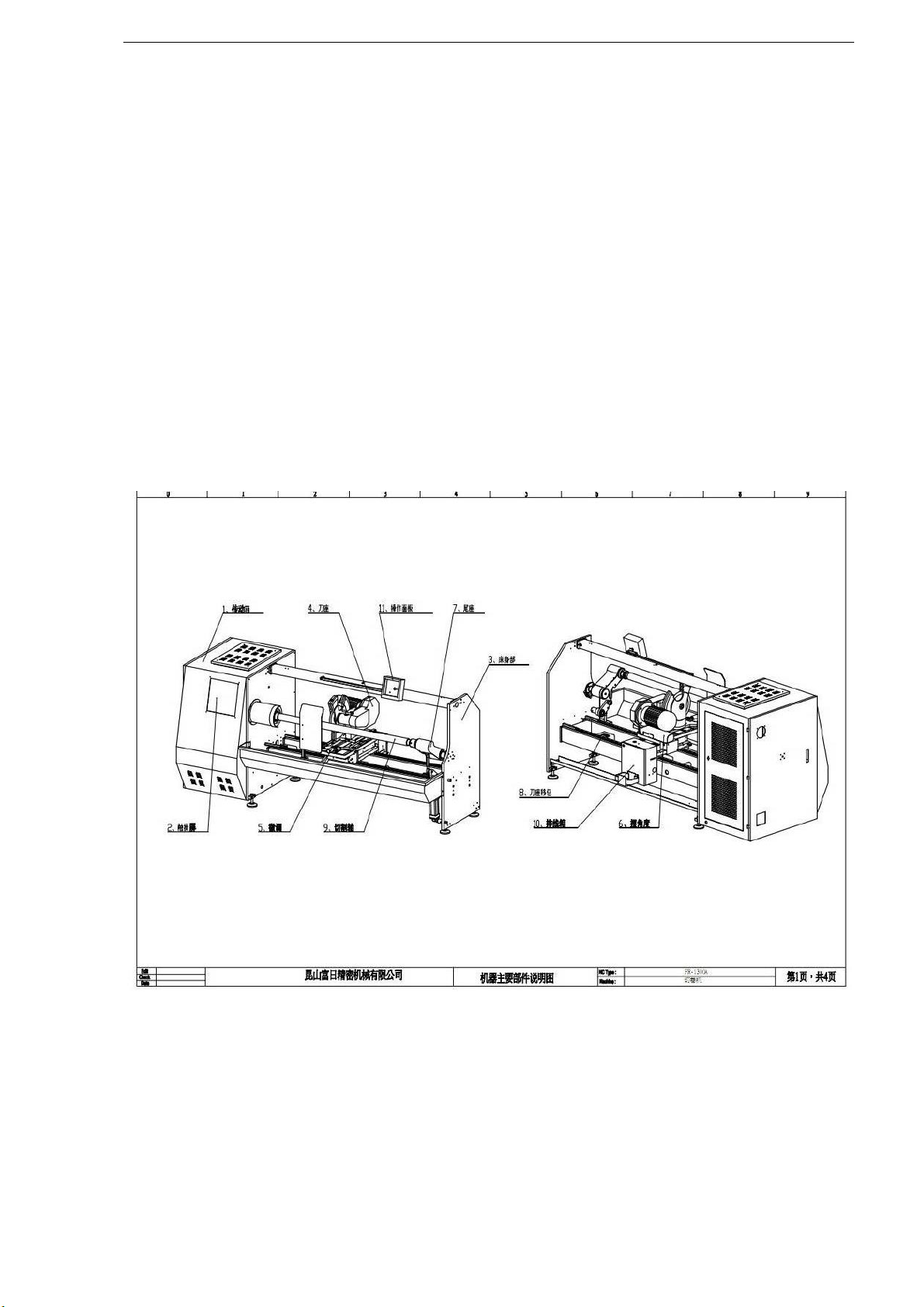
2.4 main parts ............................................................................................................. 8
2.5 machine dimension ............................................................................................... 9
3. Installation
3.1 transportation ....................................................................................................... 10
3.2 transportation method ........................................................................................... 11
3.3 installation site selection ...................................................................................... 12
3.4 installation method ............................................................................................... 13
3.5 leveling installation and adjustment ...................................................................... 14
3.6 power & air source requirement ........................................................................... 15
3.7 gas circuit............................................................................................................. 16
3.8 pneumatic component chart .................................................................................. 17
4. Operation
4.1 operating position ................................................................................................. 18
4.2 operating panel instructions .................................................................................. 19
4.3 emergency stop .................................................................................................... 31
4.4 operating procedure .............................................................................................. 32
4.5 machine adjustment .............................................................................................. 35
5. Maintenance
5.1 machine maintenance ........................................................................................... 42
5.2 machine lubrication .............................................................................................. 44
5.3 breakdown maintenance ....................................................................................... 45
5.4 easy wear parts list ............................................................................................... 45
6. Electric part
6.1 safety rules ........................................................................................................... 46
6.2 circuit diagram ..................................................................................................... 46
6.3 electric components list ........................................................................................ 46
7. After-sales service
7.1 warranty period .................................................................................................... 47
7.2 contact us ............................................................................................................. 47

Model A
Page 1 of 49
1. Operation rules
1.1 operation rules
1. The operator must focus much attention when operating the machine.
2. The operator should not wear long hair or gloves (except when handling cutting tools), and
should fasten the cuff.
3. The operator should strictly abide by the working procedure.
4. When the machine powers on, don’t open the electric control door or touch the electric
components to avoid being hurt.
5. When the tailstock spindle is in action, please keep a distance and don’t touch it.
6. Don’t put any other item except the cutting material on the cutting shaft.
7. When the machine is in operation, don’t touch the cutting shaft.
8. When the machine is in operation, don’t touch the cutting tool.
9. When the machine is in operation, don’t be close to the blade holder.
10. Don’t open the control box or touch the driving part when visually measure the machine
operation.
11. Don’t put any tool on any part of the machine.

Model A
Page 2 of 47
1.2 warning signs
Read the instruction manual carefully before starting work of any kind on the machine
Before attempting to service or maintain the machine in any way, stop the machine,
disconnect power
sources and consult the instruction manual.

Model A
Page 3 of 47
1.3 safety position drawing

Model A
Page 4 of 47
1.4 machine nameplate
The CE marking consists of the symbol shown below and the last two figures of the year in which
he mark was affixed.
The proportions of the above symbols for "CE" marking must be kept when reduced or increased in
size.
The different elements of the CE marking should have materially the same vertical dimensions,
which should not be less than 5 mm. This minimum size may be waived for small machinery.

Model A
Page 5 of 47
2. Specification
2.1 Specification sheet
Model FR-1300AB FR-1600AB
Cutting precision ±0.1mm ±0.1mm
Effective width 1320mm 1620mm
Max. Cutting diameter 380mm 380mm
Cutting core I.D. 1"-3" 1"-3"
Min. Cutting width 1mm 1mm
Circular blade diameter ø250-ø450mm ø250-ø450mm
Circular blade quantity 1 1
voltage 220V 220V
Main power 7KW 7KW
frequency 60HZ 60HZ
Machine net weight 1400KG 1500KG
Machine dimension 2950*1450*1500mm 3250*1450*1500mm

Model A
Page 6 of 47
2.2 Machine noise level
DECLARED NOISE EMISSION VALUES in accordance with ISO 7960.
Idling Operating
Declared A-Weighted Emission Sound
Pressure Level , lpAd , in dB re 20 μPa , at
the operator’s position.
69 75
Values determined according to specific test code ISO 3746.
The figures quoted are emission levels and are not necessarily safe work levels. Whilst there a correlation
between emission levels and exposure levels. This cannot be used reliably to determine whether or not
further precautions are required. Factors that influence the actual level of exposure of workpiece include
the duration of noise (i.e. The number of other adjacent machines).
Also, the permissible exposure levels can vary form country to country. The information, however, will
enable the machine user to make a better evaluation of hazard and the risk.

Model A
Page 7 of 47
2.3 Function & Feature
2.3.1 Application
Suitable for BOPP, PVC, PE, MASKING, double-sided tape, kraft paper tape, foam tape,
cloth tape, industrial tape,protection film, etc.
2.3.2 Prohibited range:
1. Non-adhesive PET 2. Non-adhesive PC 3. Release paper 4. Material thickness
above 0.2mm (not including foam) 5. Metal 6. Material diameter is above machine applicable
range
2.3.3 Feature:
1. Main driving part: Taiwan AC motor with inverter is employed.
2. Central control unit: programmable central control is used and 20 sizes can be set on the same
shaft for auto transfer and cutting.
3. Operating panel: all functions are operated on the 10" LCD touch panel.
4. Motor control system: the central control system is PLC programmable controller.
5. Cutting positioning system: cutting positioning is controlled by Mitsubishi servo motor. The
imported high precision ball screw is applied to set the size and the linear slide rail is to bear the
load of the cutter seat.
6. Blade feeding positioning system: blade feeding is controlled by Mitsubishi servo motor, and
the cutting speed is adjustable in three stages.
7. Auto angle adjustment of circular blade: Mitsubishi servo motor is used to calculate the
circular blade angle and the angle change is subject to different materials (the angle change range
is ±8°).
8. Quick shaft change system: three kinds of shafts are available and quick change of shafts is
applied for different materials.

Model A
Page 8 of 47
2.4 Main Parts
1. Driving box
2. Touch panel
3. Machine frame
4. Blade holder
5. Blade feeding fine adjustment
6. Angle adjustment
7. Tailstock
8. Cutting holder movement
9. Cutting shaft
10. Wiring box
11. Control box

Model A
Page 9 of 47
2.5 machine dimension

Model A
Page 10 of 47
3. Installation
3.1 Transportation
Pay special attention to the balance of the machine while lifting.
Use a forklift with sufficient loading capacity to lift the machine.
Have another person help guide the way when lifting the machine.
The forks of forklift must protrude from under the machine underside.
The forklift must only be driven by an experienced forklift driver.

Model A
Page 11 of 47
3.2 Transportation method
the machine can be lifted by a forklift.
Their forks should insert through the machine bottom.
Attention should be paid to the balance of the machine while lifting.
The weight of the machine is listed below.
Forklift capacity requirement:
Model Machine weight Capacity (T)
FR-1300AB
1400Kg 1400Kg+1 tons
FR-1600AB 1500Kg 1500Kg+1 tons
Transportation position specification sheet:
Item unit
model
FR-1300AB FR-1600AB
Allowable operation temperature
°C
+0
°
C~+40
°
C +0
°
C~+40
°
C
Allowable operation himidity % 85% 85%
Machine size M 2.95X1.45X1.5 3.25X1.45X1.5
Machine weight Kg 1400 1500
Machine gravity center position M 1.5X0.7*0.35 1.65X0.7X0.35
Machine placement dimension
(L*W*H) M 5.5X3.5X2.5 6.1X3.5X2.5

Model A
Page 12 of 47
3.3 Installation site selection
Requirement of operating environment the operating temperature for this machine should be
between +5 and +40℃ ℃, while the relative humidity should not exceed 50% at a maximum
temperature of +40 .℃

Model A
Page 13 of 47
3.4 Installation method
Model:FR-1300AB
Model: FR-1600AB

Model A
Page 14 of 47
3.5 Leveling installation and adjustment
1. Adjust Y axis leveling: first put the level instrument above Plate A, and adjust Feet 2 & 4, to
make the level display number within 0.04mm, then place level instrument at B, and adjust feet
1& 3 at the same procedure.
2. Adjust X axis leveling: place level instrument at roller C center, and adjust Feet 1, 3 or 2, 4
(please note two feet should be adjusted at the same time so as Y axis is not inclined).
3. Confirm X axis and Y axis leveling: place level instrument at A, B & C, to make sure the
number is within 0.04mm, if anything wrong, repeat procedure 1, 2 to make it qualified.
TOP
TOP

Model A
Page 15 of 47
3.6 power & air source requirement
1. The power is: 220V 3P
2. Air source: not below than 4.5KG

Model A
Page 16 of 47
3.7 Gas circuit

Model A
Page 17 of 47
3.8 pneumatic components chart
Model FR1300AB, FR1600AB
item model qty position
Electromagnetic vlave 4V210-08,DC24V DC AIRTEC 3
cylinder SU63*125-S-CAAIRTEC 1 Support arm
switch CS1-F SU-Ø12AIRTEC 1 Support arm
cylinder ACQ50*35-SAIRTEC 1 tailstock
switch CS1-GAIRTEC 1 tailstock
Two-point combination
pneumatic components GFC200-08AIRTEC 1

Model A
Page 18 of 47
4. Operation
4.1 operating position
Model: FR1300AB, FR-1600AB
This manual suits for next models
3
Table of contents