manuals.online logo
Brands
  1. Home
  2. •
  3. Brands
  4. •
  5. Retroaktiv
  6. •
  7. Dj Equipment
  8. •
  9. Retroaktiv MPG-70 User manual

Retroaktiv MPG-70 User manual

OWNER’S MANUAL
For mkI, mkII, and mkIII Firmware 3.0+
RETROAKTIV MPG-70 3.X USER MANUAL
2
• MPG-70 allows full integration of JX-8P, MKS-
70, and Super JX synthesizers into modern DAW
setups. The controller acts as a brand new
operating system for the synth, giving users full
control over automation, object storage, and
layering.
• Store any tone, patch, or setup with a single
press of a buon. We’ve eliminated the TONE/
TONE/PATCH architecture found on the original
MKS-70/SJX. Now you can save your sounds
quickly without the hassle of linking tones with
the patch menu.
• Multi-unit Poly Mode allows users who own two
of the same synthesizer (And it can be any synth,
not just a JX!) to daisy chain them and double
the polyphony. This will turn 2 MKS-70s into a
24-voice polyphonic synth!
• Any parameter on the synth can now be
controlled using any CC, an expression pedal, or
aeouch. The poweul ASSIGN modulation
matrix found on all Retroaktiv controllers lets
users create custom complex modulation
seings in seconds flat. Want the filter to sweep
from 50% to 60% while the resonance sweeps
from 40% to 0? MPG-70 has you covered!
• Create an INIT tone at any time from the front
panel. No more wasted time “zeroing” all of the
panel parameters. One buon press and a new
tone is initialized and ready for you to create!
• MPG-70 allows full integration of JX-8P, MKS-
70, and Super JX synthesizers into modern DAW
setups. The controller acts as a brand new
operating system for the synth, giving users full
control over automation, object storage, and
layering.
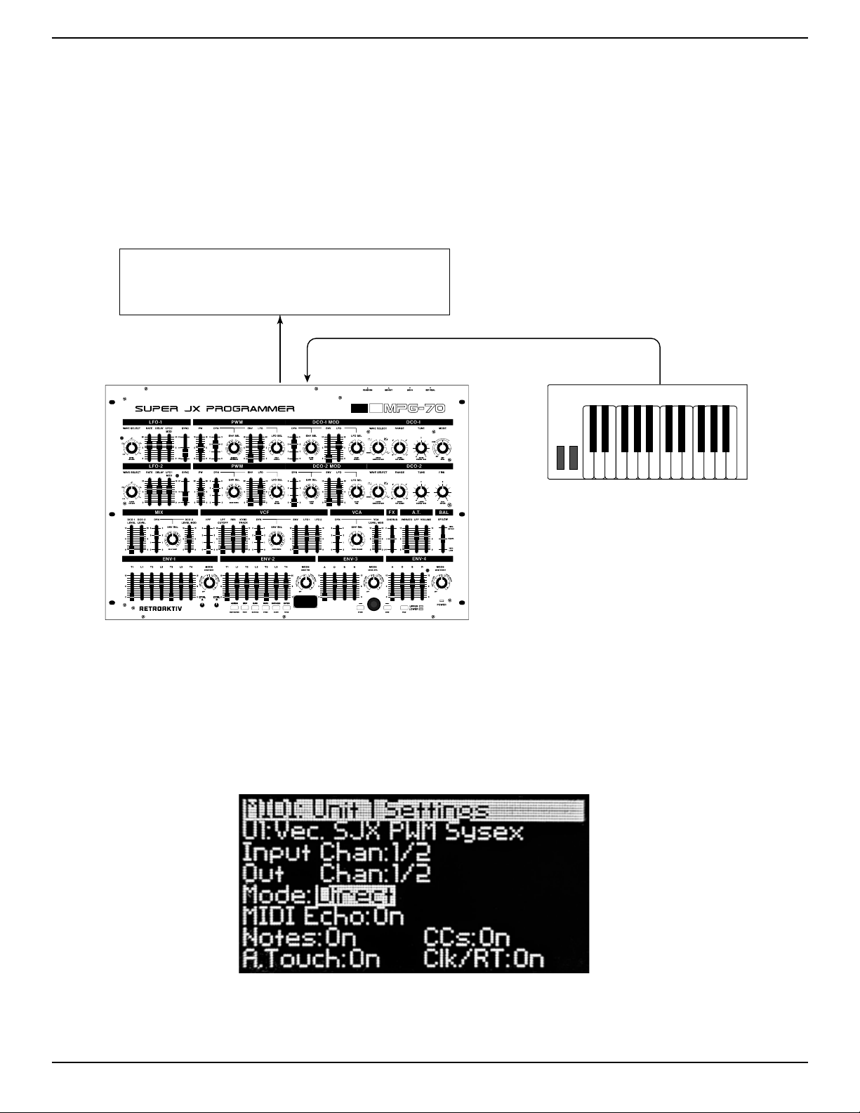
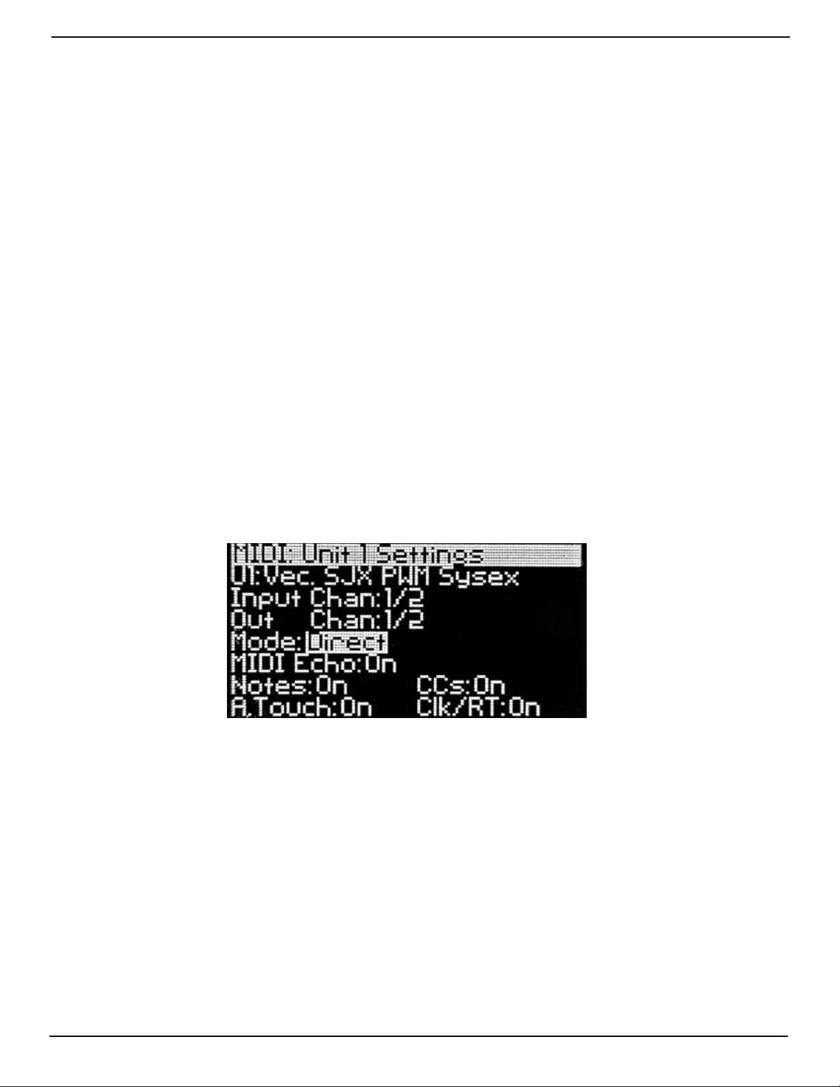
• MPG-70 can speak 11 different synth protocols,
which allows it to communicate with any stock
or Vecoven synth using CC’s, sysex, or PG-800
communication protocol. Stored MPG-70 patches
will work across all models!
• MPG-70 can upload and download banks and
individual patches from any compatible synth,
allowing easy transfer of objects to and from the
MPG-70’s internal memory banks.
• MPG-70 has a full featured patch generator,
which can generate gorgeous patches of many
different types. Users can choose from basses,
pads, polysynths, strings, brass, bells, pianos, and
organs, and the MPG-70 will never generate the
same patch twice. The patch generator can
also intelligently layer UPPER and LOWER voice
boards, to generate even more sophisticated
sounds if being used with a Super JX or MKS-70.
• All patch and tone parameters are immediately
accessible from the front panel, without any
menu diving.
• Control combinations of any 2 JX-8P, MKS-70, or
Super JX units independently. The states of both
synths can be stored as a SETUP, allowing users to
create large multitimbral textures.
• MPG-70 memory can be backed up directly to
a computer, which eliminates the need to use
external librarians to backup your objects.
• MPG-70 can be easily updated via MIDI whever
Retroaktiv issues a new soware update with new
features.
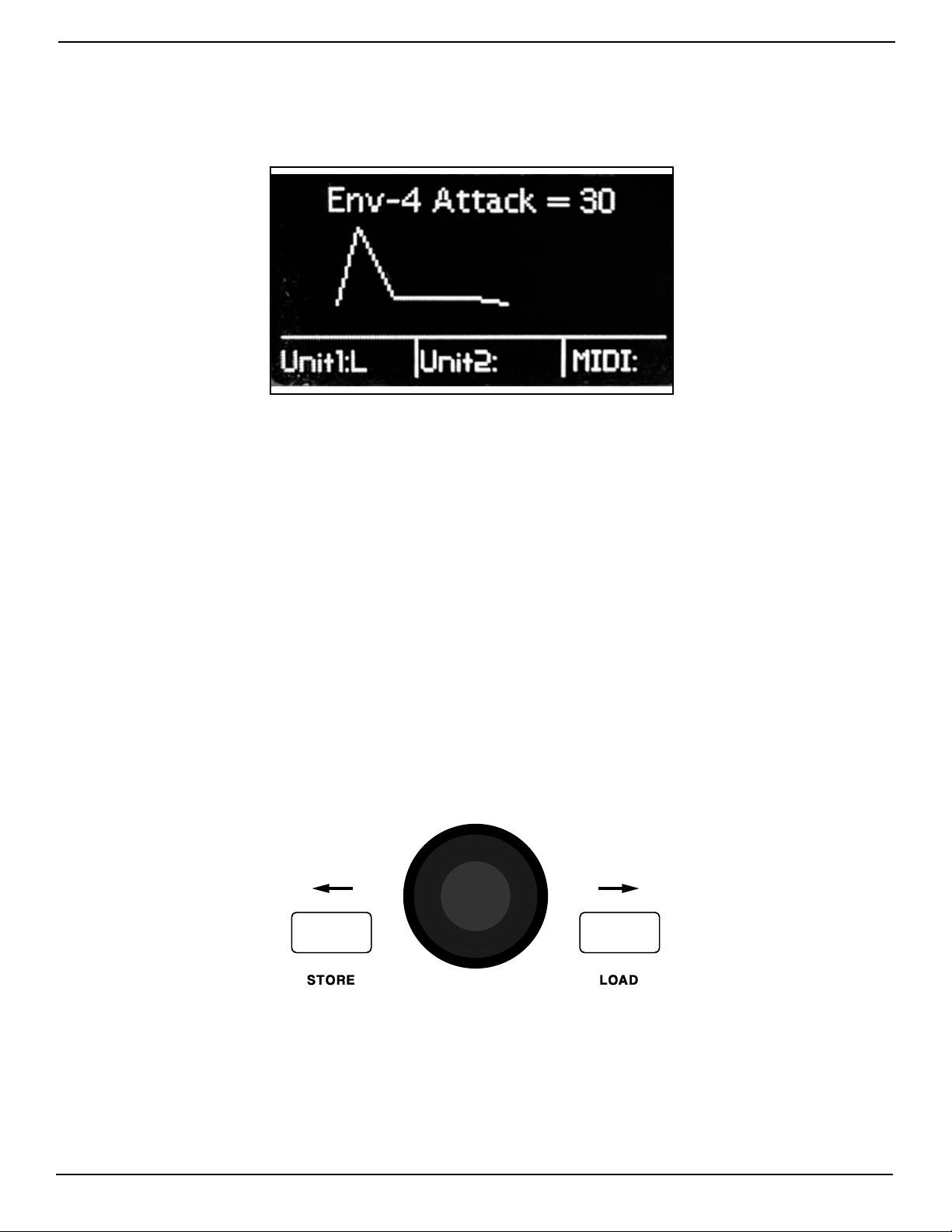
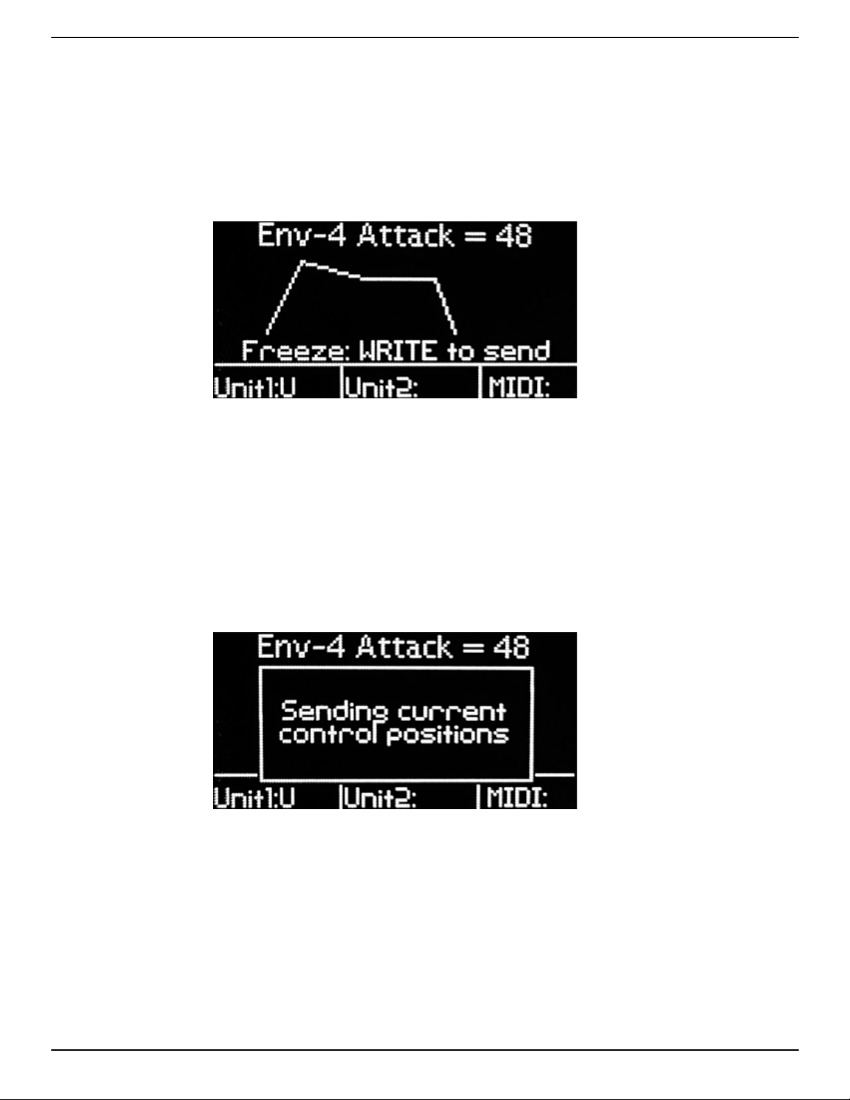
• OLED screen displays critical information such
as waveforms and envelope shapes, and allows
users to easily navigate the menu system
FEATURES
RETROAKTIV MPG-70 3.X USER MANUAL
3
17
ASSIGNABLE CONTROLLER A & B
16 ASSIGN BUTTON
15 MIDI BUTTON
14 MAIN BUTTON
13 WRITE BUTTON
12 PATCH GENERATOR BUTTON
11 ENTER BUTTON
5POWER INDICATOR
6UPPER/LOWER
BUTTON
8
CURSOR LEFT
BUTTON
7
DATA ENTRY
ENCODER
9
CURSOR RIGHT
BUTTON
10 OLED DISPLAY
1
6-PIN DIN
DATA/POWER CABLE
2MIDI OUT
3MIDI IN
4ASSIGNABLE
EXPRESSION PEDAL
PANEL DESCRIPTION:
RETROAKTIV MPG-70 3.X USER MANUAL
4
FRONT PANELFRONT PANEL
OLED DISPLAYOLED DISPLAY
The OLED display presents information about the
operation being peormed.
SECOND FUNCTIONS (PATCH)SECOND FUNCTIONS (PATCH)
The second functions are labeled on the front panel
in blue, underneath the control used to access them.
To access a second function, hold SHIFT while using
the control. All patch menu functions (In blue under
rotary pots) are accessed by holding SHIFT and
moving the pot.
UPPER & LOWER BUTTONUPPER & LOWER BUTTON
Use this buon to select which layer is being edited.
UPPER and LOWER LEDs indicate which layer is
currently selected.
CTRL A & CTRL BCTRL A & CTRL B
These knobs control ASSIGN A and ASSIGN B, which
cab be used to control combinations of different
parameters as specified by the user. See the ASSIGN
section in the manual for more details.
MENU NAVIGATION BUTTONSMENU NAVIGATION BUTTONS
The menu navigation buons are used to select
editor pages in the MPG-70. The [LEFT] and [RIGHT]
buons are used to move the cursor in the menu
pages.
The [ENTER] buon is used to execute a variety of
operations within a menu.
[MIDI], [PATCHGEN], [MAIN], and [ASSIGN] buons
are used to navigate to their respective menu
pages.
JACKS & POWERJACKS & POWER
The MPG-70 is powered via the 6-pin PG-800 jack.
Use the included 6P DIN cable with the synth or a
Retroaktiv wall supply to power MPG-70. MIDI pos
and expression pedal jacks are located on the rear
panel.
ENCODER/SHIFTENCODER/SHIFT
The black encoder knob located directly under
the OLED is used to modify values of the currently
selected parameter. If you hold down the encoder
[SHIFT], parameter values will change by larger
increments.
RETROAKTIV MPG-70 3.X USER MANUAL
5
QUICK STARTQUICK START
To begin using your MPG-70, the seings on the MPG-70 and the synth must be correct. If incorrect
seings are used, then the synth will not respond to data from MPG-70. For the best user experience, we
recommend using MIDI to edit the synth, and not PG-800, as PG-800 protocol does not allow editing of PATCH
MENU parameters or UPPER/LOWER selection. The simplest setup is shown below. Using this scheme, a
MIDI keyboard sends note data to the MPG-70, which then gets routed to the synth, along with any MPG-70
controller data.
MKS-70
MIDI IN
MIDI CONTROLLER OR DAW
To begin making sound, let’s sta by creating a basic setup. Press the [MIDI] buon on MPG-70 and set the
MPG-70 MIDI seings as shown below. Note that the U1 protocol must me set according to the synth being
used. Refer to the diagram on the next page for the correct protocol seing for each synth type. Using the
seings below, the synth must be set to receive SYSEX and the synth’s MIDI channel must be set to channel 1.
Basic MIDI menu seings on the MPG-70
Basic MIDI configuration
RETROAKTIV MPG-70 3.X USER MANUAL
6
An alternative connection scheme involves a MIDI MERGER unit. This allows for bidirectional communication
between the synth and the MPG-70 (For exchanging objects like PATCHES, TONES, and BANKS). If using a MIDI
MERGER, use the scheme pictured below.
MKS-70
MIDI IN
MIDI CONTROLLER OR DAW
MIDI MERGER
MIDI IN MIDI IN
MIDI OUT
MIDI OUT
COMMUNICATIONS PROTOCOLSCOMMUNICATIONS PROTOCOLS
In the MPG-70 MIDI Seings menus, the U1 and U2 seings must correspond to the synth being controlled.
Incorrect seings here will result in no response from the synth when being edited. The 11 MPG-70 protocols
are listed below.
SJX Sysex - Sysex protocol Super JX and MKS-70 synthesizers
JX-8P Sysex - Sysex protocol stock JX-8P synthesizers
SJX/JX-8P PG-800 - PG-800 protocol for stock JX-8P, MKS-70 and Super JX synthesizers
Vecoven SJX Sysex - Sysex protocol for Vecoven 3.x Super JX and MKS-70 synthesizers
Vecoven SJX PWM Sysex - Sysex protocol for Vecoven 4.x Super JX and MKS-70 synthesizers with PWM
Vecoven JX-8P Sysex - Sysex protocol for Vecoven 5.x JX-8P synthesizers
Vecoven JX-8P PWM Sysex - Sysex protocol for Vecoven 6.x JX-8P synthesizers with PWM
Vecoven SJX PG-800 - PG-800 protocol for synthesizers with Vecoven 3.x
Vecoven SJX PWM PG-800 - PG-800 protocol for synthesizers with Vecoven 4.x with PWM
Vecoven JX-8P PG-800 - PG-800 protocol for Vecoven 5.x JX-8P synthesizers
Vecoven JX-8P PWM PG-800 - PG-800 protocol for Vecoven 6.x JX-8P PWM synthesizers
USING THE INCORRECT PG-800 PROTOCOL WITH YOUR SYNTH CAN RESULT IN THE SYNTH MEMORY BEING ERASED.
MAKE SURE THAT YOU ARE USING THE CORRECT COMMUNICATION PROTOCOL WITH YOUR SYNTH!
RETROAKTIV MPG-70 3.X USER MANUAL
7
SETTINGS ON THE SYNTHESIZERSETTINGS ON THE SYNTHESIZER
The seings on the synth’s MIDI menu must be correct for communication to work. For a SUPER JX or MKS-70,
the MIDI UPPER and LOWER channels should be the same, and must correspond to the channel seings on
MPG-70. SYSEX IPR and SYSEX APR must be turned ON. On Vecoven modified units, the communication
protocols for PG-800 (if used) and SYSEX (if used) must be activated.
FIRMWARE VERSION & MEMORY CARDFIRMWARE VERSION & MEMORY CARD
upon powering up the MPG-70, a splash screen will be displayed on the OLED. This splash screen will first
display the firmware version currently running on MPG-70, and if a memory card is present, will display the
status of the memory card.
If there is an issue with the memory card, the unit will boot with a message indicating the problem, and will
give an error code. If this happens, please contact Retroaktiv for the error code diagnosis.
If using PG-800 protocol with a Vecoven PWM modified synth, the MPG-70 must handshake with the synth
during the boot process. The splash screen will remain on the display until a successful handshake occurs,
or the operation times out. If there is a time-out, then all extra Vecoven parameters, such as extra LFOs and
ENVs will not respond.
MPG-70 Splash Screen with firmware version
Memory Expansion OK indicates presence of a memory card
RETROAKTIV MPG-70 3.X USER MANUAL
8
MENUS AND NAVIGATIONMENUS AND NAVIGATION
When MPG-70 boots up, it will display the MAIN menu screen. The diagram below shows the contents displayed
on the MAIN screen.
MPG-70 Navigation Console
MPG-70 MAIN Screen
The MAIN screen displays the following information:
1 - Current active parameter name and value
2 - Unit 1 Active Layers (U, L, or U+L if UPPER and LOWER layers are both selected)
3 - Unit 2 Active Layers (U, L, or U+L if UPPER and LOWER layers are both selected)
4 - MIDI Input Monitor - Displays channel of incoming MIDI activity received at MPG-70 MIDI IN po.
To return to the MAIN screen at any time, press the [MAIN] buon in the navigation console.
The encoder and arrow buons are used to navigate menus and change seings. The SHIFT function refers
to the switch on the encoder knob. To engage the SHIFT function (used for double-buon combos such as
SHIFT+MIDI buon = MIDI Panic), press and hold the encoder knob. To increment a value with the encoder,
simply turn the encoder knob. To increment or decrement by 8, hold the SHIFT buon in while turning the
encoder.
Use the [MIDI], [PATCHGEN], [ASSIGN], and [MAIN] buons to navigate to the different menu pages. To move
the cursor on a menu page, use the [LEFT] and [RIGHT] buons. To change the value of a highlighted menu
seing, use the [ENCODER] dial.
RETROAKTIV MPG-70 3.X USER MANUAL
9
THE FREEZE FUNCTIONTHE FREEZE FUNCTION
Pressing WRITE from the MAIN screen will enable the “FREEZE” function on MPG-70. When FREEZE is enabled,
a message will be displayed “Freeze : WRITE to send.”. When FREEZE is on, moving a slider will not send a
message. When ENTER is pressed, the new location of any slider moved during the FREEZE operation will be
sent to the synth. This is an excellent way to send a large number of slider changes all at once, at the exact
moment ENTER is pressed.
Freeze mode
MANUAL MODEMANUAL MODE
Pressing SHIFT + WRITE will transmit all of the control positions on the panel to the synth. When this is done,
the seings on the synth will correspond to the current seings on the MPG-70 front panel.
Manual Mode
INIT TONEINIT TONE
To create an INIT TONE (A generic tone that functions as a basic staing point when creating a new sound),
press SHIFT + PATCHGEN.
RETROAKTIV MPG-70 3.X USER MANUAL
10
THE MIDI MENUS AND FUNCTIONSTHE MIDI MENUS AND FUNCTIONS
MIDI:SETTINGSMIDI:SETTINGS
The MIDI Seings menu contains all of the parameters that determine which MIDI channels the MPG-70
receives data on, and which channels outgoing data will be transmied on. This page is also where we
configure which types of MIDI data the MPG-70 will pass to the synth, as well as CC to sysex translation.
Press MIDI once to navigate to the Unit 1 Seings page, and press MIDI again to navigate to the Unit 2 Seings
page.
U1 & U2:U1 & U2:
This is where the communication protocol for the synthesizer is selected. See page 6 for the list of available
communication protocols.
INPUT CHAN:INPUT CHAN:
Selects which MIDI input channels MPG-70 will respond to. Only selected channels will be relayed to the synth
(on the MIDI OUT channels selected), while all others will be ignored. Note that if 1/2 is selected, this means
that MPG-70 will process any data received on channel 1, and if CC TRANSLATE is enabled, incoming CCs on
channel 2 will also be processed. (Because when using CC TRANSLATE, 2 channels are used. One for the
LOWER voice board, and one for the UPPER voice board. See MODE below for more details)
The MIDI:Seings Menu
OUT CHAN:OUT CHAN:
Selects the channel that outgoing SYSEX, NOTE, CC, PITCH, and AFTERTOUCH data will be transmied on. Any
data received on the INPUT CHANNEL will be passed to the synth on the OUTPUT CHANNEL. For example, if
INPUT CHAN is set to 1/2, and OUT CHAN is set to 3/4, note data received by MPG-70 on channel 1 would be
transmied to the synth on channel 3. This function is a great way to prevent MIDI feedback loops, as any
data received on channel 3 at the input, would be ignored and not passed to the synth. The synth should be
set to receive on the same channel as the OUT CHAN seing.
MODE:MODE:
There are 2 selectable modes on the MPG-70: DIRECT and CC SEND/TRANSLATE.
DIRECT: Select this mode to send either SYSEX or PG-800 messages to the synthesizer.
RETROAKTIV MPG-70 3.X USER MANUAL
11
CC SEND/TRANSLATE: Select this mode if recording CCs using a DAW or SEQUENCER. When using this mode,
the panel controls will send a CC when toggled. This CC can be recorded by a DAW, and when sent back to the
MPG-70, will be translated back into a SYSEX or PG-800 message and transmied to the synthesizer. MPG-70
does not suppo NRPN CCs, as this would require several more protocols spanning all of the different Vecoven
synthesizers. The CC method used by the MPG-70 is universal across all of the different suppoed synths, and
will work with stock and Vecoven modifed units. For a list of CC parameter IDs, see the cha below.
MIDI ECHO:MIDI ECHO:
When enabled, any valid MIDI message received on INPUT CHAN will be transmied on the MIDI OUT po of the
MPG-70 on the OUT CHAN. When disabled, date received on the MIDI IN po will be ignored.
DATA FILTERS:DATA FILTERS:
Different types of MIDI data chan be filtered by the MPG-70. When a data type is set to ON, that data type will
be passed through the MPG-70. NOTE, CC data, AFTERTOUCH, and CLOCK/REALTIME data can be filtered. If
PITCH BEND or SYSEX needs to be filtered, this can be toggled on the synth itself.
CC TO SYSEX TRANSLATECC TO SYSEX TRANSLATE
MPG-70 allows users to record and translate buon presses and fader movements with any DAW or sequencer,
by allowing CC to sysex translation.
When this mode is enabled, moving sliders and toggling buon parameters will send a CC message from the
MPG-70 instead of a sysex message.
When using the MPG-70 to translate CC messages into sysex messages for the MKS-70, each of the TONE layers
on each UNIT has its own MIDI channel. For example if the UNIT 1 IN channel is set to 1(2), and the UNIT 2 IN
channel is set to 3(4), then incoming CCs on channel 1 would affect UNIT 1 UPPER tone parameters, CCs on
ch 2 would affect UNIT 1 LOWER tone parameters. CCs on channels 3 and 4, would affect UNIT 2 UPPER and
LOWER layers respectively. This table shows the implementation of the MPG-70 MIDI CC to SYSEX translation.
3 DCO-1 WAVE SEL
9 DCO-1 RANGE
12 DCO-1 COARSE
13 DCO-1 LFO AMT
14 DCO-1 LFO SEL
15 DCO-1 ENV AMT
16 DCO-1 ENV DYN
17 DCO-1 ENV SEL
18 DCO-1 PW
19 DCO-1 PW LFO AMT
20 DCO-1 PW LFO SEL
21 DCO-1 PW ENV DYN
22 DCO-1 PW ENV AMT
23 DCO-1 PW ENV SEL
24 DCO-2 WAVE SEL
25 DCO-2 RANGE
26 DCO-2 COARSE
27 DCO-2 LFO AMT
28 DCO-2 LFO SEL
29 DCO-2 ENV DYN
30 DCO-2 ENV AMT
31 DCO-2 ENV SEL
32 DCO-2 PW
33 DCO-2 PW LFO AMT
34 DCO-2 PW LFO SEL
35 DCO-2 PW ENV DYN
36 DCO-2 ENV MOD AMT
37 DCO-2 PW ENV SEL
38 DCO MODE
39 DCO-2 FINE TUNE
40 HPF
41 LPF CUTOFF
42 RESONANCE
43 VCF LFO-1 AMT
44 VCF LFO-2 AMT
45 VCF KEY FOLLOW
46 VCF ENV DYN
47 VCF ENV AMT
48 VCF ENV SEL
49 LFO-1 WAVE SEL
50 LFO-1 RATE
51 LFO-1 DELAY
79 ENV-2 T1
80 ENV-2 T1
81 ENV-2 T2
82 ENV-2 T3
83 ENV-2 T4
84 ENV-2 L1
85 ENV-2 L2
86 ENV-2 L3
87 ENV-2 MODE
88 ENV-3 ATTACK
89 ENV-3 DECAY
90 ENV-3 SUSTAIN
91 ENV-3 RELEASE
92 ENV-3 MODE
93 ENV-4 ATTACK
94 ENV-4 DECAY
95 ENV-4 SUSTAIN
96 ENV-4 RELEASE
97 ENV-4 MODE
102 VCA ENV AMT
103 VCA ENV SEL
104 VCA ENV DYN
52 LFO-1 MOD
53 LFO-1 SYNC
54 CHORUS
55 DCO-1 MIX
56 DCO-2 MIX
57 MIX ENV DYN
58 MIX ENV AMT
59 MIX ENV SEL
60 LFO-2 WAVE SEL
61 LFO-2 RATE
62 LFO-2 DELAY
63 LFO-2 MOD
70 LFO-2 SYNC
71 ENV-1 T1
72 ENV-1 T2
73 ENV-1 T3
74 ENV-1 T4
75 ENV-1 L1
76 ENV-1 L2
77 ENV-1 L3
78 ENV-1 MODE
RETROAKTIV MPG-70 3.X USER MANUAL
12
MIDI: GLOBAL SETTINGSMIDI: GLOBAL SETTINGS
The MIDI: Global Seings pages contain parameters that affect global seings on the MPG. To navigate to this
menu page, press [MIDI] until the menu shown below is displayed on the OLED.
The MIDI: Global Seings page
MULTI-UNIT POLY MODE:MULTI-UNIT POLY MODE:
Multi-Unit Poly Mode mode is for setups that utilize two MKS-70 synthesizer modules, or two of any other
synthesizer (Not just synths suppoed by MPG-70). When enabled, this will treat 2 identical synths as a single
synthesizer with double the polyphony.
It is impoant to understand that when Multi-Unit Poly Mode is enabled, the MPG-70 will consider the 2
connected MKS-70s to be a single 24-voice polyphonic synth. For this reason, when using this mode, UNIT 1 and
UNIT 2 should both be selected. This will allow you to load the same patch on both units, so both units have
the same sound loaded. Below is an example scheme for using Multi Unit Poly Mode. In this example Multi-
Unit Poly Mode must be turned ON in the Global Seings menu. Playing notes into MPG-70 on MIDI PORT 1 on
channel 1 will play the two MKS-70 units as a single 24-voice synth. The diagram below shows a typical Multi-
Unit Poly Mode setup.
MKS-70 UNIT 1 (Ch 1)
MIDI IN
MIDI CONTROLLER OR DAW (Ch 1)
MIDI OUT
MKS-70 UNIT 2 (Ch 3)
MIDI IN MIDI OUT
MIDI THRU
RETROAKTIV MPG-70 3.X USER MANUAL
13
PROGRAM CHANGE MODE:PROGRAM CHANGE MODE:
This determines how incoming program change messages are handled by MPG-70.
INTERNAL - When a program change is received, it will be used to select an object stored in MPG-70 internal
memory.
ECHO - When a program change message is received, it will be transmied out to the MKS-70, and will not
select an MPG-70 object.
INTERNAL + ECHO - When program change is received, it will select an object from MPG-70 internal memory,
athen the program change message will be sent to the MKS-70 as well.
When INTERNAL program change is selected, each type of MPG-70 object can be recalled using MIDI program
changes. Using this function, any tone, patch, assign or setup can be selected using MIDI program change
and bank change messages. Below is a list of the functions that can be toggled in INTERNAL.
Patch U1 - Sets MIDI channel that Unit 1 Patch program change messages will be selected on.
Patch U2 - Sets MIDI channel that Unit 2 Patch program change messages will be selected on.
Tone U1 Upper - Sets MIDI channel that Unit 1 Upper Tone program change messages will be selected on.
Tone U1 Lower - Sets MIDI channel that Unit 1 Lower Tone program change messages will be selected on.
Tone U2 Upper - Sets MIDI channel that Unit 2 Upper Tone program change messages will be selected on.
Tone U2 Lower- Sets MIDI channel that Unit 2 LowerTone program change messages will be selected on.
Assign - Sets MIDI channel that ASSIGN program change messages will be selected on.
Setup - Sets MIDI channel that SETUP program change messages will be selected on.
CHORD MODE:CHORD MODE:
The MPG-70 CHORD MODE function allows users to input a chord, and then play it by keying a note. The chord
will be transposed anywhere on the keyboard where a new note is keyed. CHORD MODE can be enabled on
UNIT 1, Unit 2, or BOTH units. Once enabled, a menu dialog will appear, showing the notes in the current CHORD.
(ChordNt) Each of the notes in the chord can be entered manually, using the cursor and encoder, or the chord
can be entered into the MPG-70 by holding SHIFT and playing a chord into the unit. To clear the current chord,
press SHIFT to delete the current chord contents.
Chord Mode will allow 12 notes to be on at one time. Depending on the size of the chord and how many notes
being held, the MPG will not “steal” voices. It will instead play the chords with any available voices.
Note: Chord Mode creates a large amount of MIDI data, which must all be passed in sequence to the synth.
If you are trying to play a lot of notes with a large chord, and simultaneously send slider data, there may be
timing issues, as all of the data cannot be passed to the synth quickly enough to prevent a delay.
RETROAKTIV MPG-70 3.X USER MANUAL
14
MIDI: SYSEX MENUMIDI: SYSEX MENU
To navigate to MIDI:Sysex menu, press the MIDI buon until MIDI:Sysex is displayed in the menu bar at the top
of the screen. The MIDI sysex menu is used for impoing and expo patches and bank data. Here is a brief
explanation of each function in this menu:
The MIDI:Sysex Menu
SEND JX/MKS BANK - Use this function to send a bank of patches to an MKS-70/JX from the MPG-70’s internal
memory. Select the bank on the MPG-70 to be transmied, then press ENTER to initiate the transfer. Note:
for this to work, bidirectional communication between the MPG-70 and MKS-70 is required. This means that
the MPG-70 MIDI OUT is routed to MKS-70 MIDI IN, and the MKS-70 MIDI OUT is routed to MPG-70 MIDI IN. When
transferring a bank of patches from MPG-70, it should be understood that the format of PATCH objects in the
MPG-70/JX is different than the format of PATCH objects in the MKS-70 memory. In the MKS-70, there are 100
tones, and 64 patches, with each patch linking to 2 of the 100 tones. In MPG-70, we’ve eliminated the tedious
TONE/PATCH linking required in MKS-70/SJX. Since we no longer use linked tones, when dumping MPG-70
format banks to MKS-70/SJX, we are limited to 25 patches per bank (Because MKS-70 only allows for 50 user
tones to be stored in memory, and each patch takes 2 tones). This is the compromise that was needed in
order to allow “one touch patch storage” in MPG-70.
RECEIVE JX/MKS BANK - Use this function to request a bank of patches from the MKS-70. Note: for this to work,
bidirectional communication between the MPG-70 and MKS-70 is required. Select the destination bank in the
MPG-70 and hit ENTER to load the MKS-70 bank to the destination bank. Note that instead of sharing tones,
like the MKS-70 does, the MPG-70 will store the incoming patches as 25 patches, each with their own 2 tones,
thus eliminating the linkage between each tone and any other patch. This means that if a “shared” tone is
edited and stored on the MPG-70, it will not affect any other patches that also use that tone.
SEND MKS/JX TONE - This sends the current TONE to the MKS-70, where it can then be stored in MKS-70 format.
Understand that when doing this, you may overwrite tones that are shared by other patches.
RECEIVE MKS/JX TONE - Downloads the current tone from MKS-70 into the selected destination and conves it
into MPG-70 format.
RETROAKTIV BANK SEND/RECV - Expos or impos a bank of MPG-70 format patches in MPG-70 to a computer
sysex librarian. Note that these will be in MPG-70 format, not MKS-70 format. Bidirectional communication not
required for this operation.
STORAGE BACKUP - Expos a backup of all ASSIGN, PATCH, SETUP and TONE objects from the MPG-70. USed for
backing up the contents of memory. Bidirectional communication not required.
STORAGE RESTORE - Allows a full-card backup file to be impoed to the MPG-70. Warning: This will overwrite
RETROAKTIV MPG-70 3.X USER MANUAL
15
the entire MPG-70 memory bank.
CONVERTING AN MKS-70 BANK INTO RETROAKTIV PATCH FORMATCONVERTING AN MKS-70 BANK INTO RETROAKTIV PATCH FORMAT
MPG-70 cannot receive MKS-70 banks directly from the computer. To do this type of transfer, the sound bank
must first be formaed to the Retroaktiv format. Once in this format, the bank can be loaded into the MPG-70
directly from the computer. The Retroaktiv PATCH format eliminates the “tone sharing” scheme used on the
MKS-70. To conve an MKS-70 bank to Retroaktiv Non-Shared format, connect the programmer and synth as
shown below.
To conve a bank, do the following:
1. Send the bank from the computer to the MKS-70
2. Use the Receive MKS-70 Patch Bank function in the MPG-70 Sysex Menu to load the bank into the MPG-70.
3. Use the Send Patch Bank function in the MPG-70 Sysex Menu to send the bank to the computer. (Once in
the MPG-70, the bank has been conveed into Retroaktiv Patch format)
4. Now the conveed bank can be dumped directly to MPG-70 from the computer using the Receive Patch
Bank function in the Sysex Menu. The conversion just needs to be done once, then the bank can be
directly loaded into MPG-70 from a sysex librarian.
The conversion of MKS-70 banks is necessary because if a bank contains tones that are not pointed to by
patches in the MKS-70, then those tones will be lost, resulting in the transferred bank not being a carbon copy
of the original. Using the process above, no tone data will ever be lost. Once an MKS-70 bank is conveed into
Retroaktiv format, it can be expoed to a PC in Retroaktiv format, and dumped back into any MPG-70 directly
from the computer, without going through the MKS-70 first.
MKS-70
MIDI IN MIDI OUT
An example of bidirectional communication with the MKS-70
RETROAKTIV MPG-70 3.X USER MANUAL
16
MIDI: USER CC MAPSMIDI: USER CC MAPS
The MPG-70 allows users to create their own user CC maps, which allow the MPG-70’s control suace to be
programmed to transmit CCs from any slider, making it ideal for controlling external gear.
To use a CC map, navigate to Unit 2 MIDI: Seings page and select User CC as the unit type. The menu shown
below will be displayed.
The MIDI:CC Map Menu
Creating a User CC Map:
When on the User CC Map page, moving any slider will display that slider’s current CC# routing, as well as the
MIDI channel that CC slider will transmit on. The encoder can then be used to enter which CC# each slider
transmits on. Each slider can transmit on any CC and any channel independently.Each slider can transmit on any CC and any channel independently.
Pressing [ENTER] when in the User CC Map menu will cycle through all sliders that have active CC routings,
making it simple to see which sliders in a map are active.
The Default state of the User CC Map feature is OFF. A User CC Map can only be used on the UNIT 2 layer of
the MPG-70 when Unit 2 is set to User CC.
Clearing a User CC Map:
To clear all slider routings in a User CC Map, press [SHIFT]+[MIDI].
Storing and Loading User CC Maps:
MPG-70 internal memory can store 32 User CC Maps. To store or load a map, go to the User CC Map menu, and
press the STORE or LOAD buon once. A list of currently stored CC maps will be displayed. Select the desired
slot to be loaded or stored, then press the [STORE] or [LOAD] buon. A CC map can be stored with a SETUP.
RETROAKTIV MPG-70 3.X USER MANUAL
17
THE PATCH GENERATORTHE PATCH GENERATOR
The Patch Generator tool is a poweul feature that creates intelligently randomized tones, as well as preset
“Init tones”. This tool provides an endless supply of new, musical tones and patches. Here’s how it all works:
The Patch Generator uses categories so users can tell it which type of sound to create. Below is a cha
showing the various categories and subcategories, as well as a brief description of the types of sounds each
will generate. Note that these category and subcategory names are being used as “musical adjectives” to
describe characteristics of a sound. This common reference we all have allows us to easily categorize the
types of sounds we want the patch generator to create.
The Patch Generator Menu
GENERATING A TONEGENERATING A TONE
To generate a tone, select a category/sub-category, then use the [EDIT SEL] and [LAYER] buons to select
which synth layers the tone will be generated on. Press ENTER from the PATCHGEN page to generate a new
patch.
Each section of the synth has its own ENABLE in the patch generator menu. Sections shown in the menu
correspond to the sections labeled on the front panel. (DCO-1,DCO-2, VCF, LFO, MIXER, ADSR ENV, TL
ENV, CHORUS, VCA, and AMP MOD) Seing a section’s ENABLE to OFF prevents the patch generator from
randomizing any of the parameters in that section when a new tone is created. To disable all sections, press
PATCHGEN buon. Pressing the PATCHGEN buon again enables all sections. This shocut makes it simple to
do something such as disable all sections, then set just one section to ON.
The patch generator is able to create multi-layer as well as single layer patches. It will select the KEY MODE
and ASSIGN MODE according to the type of patch it is trying to create.
The VCA of the MKS/SJX/8P can disto. This happens at a different level from unit to unit. If you experience
distoion when generating patches, simply mask VCA and set the VCA LEVEL MOD slider to where it doesn’t
disto.
PATCH GENERATOR CATEGORIESPATCH GENERATOR CATEGORIES
•• BASS - ALL, DECAY TO 0, SUSTAIN, RELEASEBASS - ALL, DECAY TO 0, SUSTAIN, RELEASE
•• PADS - STEAM/AIR, BELL PADS, POLY PADS, GENERAL, ENV DETUNEPADS - STEAM/AIR, BELL PADS, POLY PADS, GENERAL, ENV DETUNE
•• POLY - ALLPOLY - ALL
•• BELLS - ALL, GENERAL, KLANGBELLS - ALL, GENERAL, KLANG
•• BRASS - ALLBRASS - ALL
•• STRINGS - ALLSTRINGS - ALL
•• ORGAN - ALL, TONEWHEEL, PIPEORGAN - ALL, TONEWHEEL, PIPE
•• PIANO - ALL, EL. PIANO, PIANO + STRINGSPIANO - ALL, EL. PIANO, PIANO + STRINGS
RETROAKTIV MPG-70 3.X USER MANUAL
18
ASSIGNASSIGN
The ASSIGN functions on the MPG-70 are a poweul MIDI modulation matrix, which allows users to create
complex modulation of multiple MKS-70 parameters using one control source, such as the ASSIGN sliders, an
expression pedal, aeouch, or any CC.
Each of the 7 assignable control sources can control up to 5 simultaneous parameters independently on anyEach of the 7 assignable control sources can control up to 5 simultaneous parameters independently on any
layer of either synth plugged into the MPG-70.layer of either synth plugged into the MPG-70. This allows us to do something like sweep the filter cutoff up on
the UPPER layer, while sweeping the cutoff down on the LOWER layer. Using the assigns and combinations of
assigns, a sound can be animated in ways not possible on other controllers.
To access the ASSIGN menu, press the ASSIGN buon once. The ASSIGN menu will be displayed on the OLED.
This menu gives us access to all of the parameters contained in the assignable control matrix.
The Assign Menu
ASSIGN SOURCEASSIGN SOURCE
There are 7 different ASSIGNs (Control sources):
CTRL A KnobCTRL A Knob
CTRL B KnobCTRL B Knob
Expression Pedal JackExpression Pedal Jack
AeouchAeouch
CC Source 1 (Any CC# 0-127)CC Source 1 (Any CC# 0-127)
CC Source 2 (Any CC# 0-127)CC Source 2 (Any CC# 0-127)
CC Source 3 (Any CC# 0-127)CC Source 3 (Any CC# 0-127)
The CTRL A and B sliders are located in the ASSIGN section of the MPG-70 front panel.
The Expression Pedal source is connected to the EXP PEDAL jack on the rear panel of the MPG-70. Only
use passive expression pedals with the MPG-70. Do not use a powered expression pedal.Do not use a powered expression pedal. This can result in
damage to the controller.
The Aeouch ASSIGN responds to incoming aeouch messages on the UNIT 1 and UNIT 2 MIDI IN channels.
CC Source 1-3 are controlled by incoming CC messages (CC#0 - CC#127) on the UNIT 1 and 2 MIDI IN channels.
These ASSIGNs are a great way to create automated “lanes” using a DAW. To automatically get the MPG-70 to
route a CC ASSIGN to a CC, simply navigate to the desired CC ASSIGN, hold [SHIFT] and move the CC (Such as
a mod wheel) and the MPG-70 will automatically route that CC to the ASSIGN.
RETROAKTIV MPG-70 3.X USER MANUAL
19
DESTINATIONS AND ROUTINGDESTINATIONS AND ROUTING
Each of the 7 ASSIGN sources has 5 available destinations (parameters on the MKS-70) it can control. Each
parameter being controlled by an assign has its own range, polarity, UNIT destination (Unit 1, 2, or BOTH), and
layer destination (UPPER/LOWER/BOTH)
•• Dest (1-5)Dest (1-5): Selects which destination is being edited in the ASSIGN menu.
•• PARAMPARAM: Selects which parameter will be the current destination.
•• MINMIN: sets the minimum value of the current assign destination.
•• MAXMAX: sets the maximum value of the current assign destination.
•• UNIT 1UNIT 1: Selects which layers of Unit 1 the current destination will be routed to.
•• UNIT 2UNIT 2: Selects which layers of Unit 2 the current destination will be routed to.
•• INVERT/NORMALINVERT/NORMAL: Sets the direction (up or down) this parameter value will move in when the SOURCE value
is changed.
For example, if we use CTRL A as a SOURCE, then select Filter Cutoff as Destination 1, moving the CTRL A knob
will affect the Filter Cutoff parameter. To set the range of the filter control, we select the MIN and MAX values.
If MIN = 50 and MAX = 75, then moving the CTRL A knob from boom to top of its travel, will sweep the Filter
Cutoff between 50 and 75. If we want the response to be inveed, so moving the CTRL A knob up sweeps the
Filter Cutoff down from 75 to 50, then INVERT can be selected.
All of the 5 destinations within each ASSIGN can be routed in this way to any parameters on the synth. This
allows the user to create complex real-time modulations, which would normally require many hands or many
overdubs to accomplish, in a single movement.
To deactivate an ASSIGN layer, simply select NONE as the destination in a layer, and the routing will be
deactivated for that layer.
There are a few guidelines to follow to maximize the MIDI peormance of the MPG-70 when using assigns.
An ASSIGN has the potential to generate large amounts of MIDI data. If you’re using an ASSIGN with 5
layers, which is routed to BOTH layers of the synthesizer, this will generate 10 MIDI sysex messages with each
movement of the ASSIGN source. This amount of midi data can take many tens of milliseconds to transmit to
the synthesizer. If using many large ASSIGNs at one time, it may even be possible to ovelow the synth’s MIDI
buffer (Which holds incoming MIDI messages while the synth processes each one in the buffer).
ASSIGN Enable & Disable - Pressing the ASSIGN buon will alternate between the ASSIGN menu and the ASSIGN
Enable menu. Each of the 7 assigns has its own global enable, allowing you to turn the assigns on only when
you wish to use them.
Clear all ASSIGNS - To clear all ASSIGN data, navigate to the ASSIGN menu, then press [SHIFT]+[ASSIGN].
Clearing current ASSIGN - SHIFT + PATCHGEN
RETROAKTIV MPG-70 3.X USER MANUAL
20
INTUITIVE ENTRY OF ASSIGN LAYERSINTUITIVE ENTRY OF ASSIGN LAYERS
While users can manually enter all of the necessary information into each ASSIGN layer, this can become
tedious when creating many different routing destinations. To speed up the ASSIGN creation process, a
shocut can be used to quickly enter a destination’s parameters.
Begin by navigating to the source and destination to be edited.
Hold down the SHIFT buon and move the destination slider through the desired range and direction (UpHold down the SHIFT buon and move the destination slider through the desired range and direction (Up
= normal, down = inveed) and release the SHIFT buon when finished. The PARAM, MIN, MAX, and INVERT= normal, down = inveed) and release the SHIFT buon when finished. The PARAM, MIN, MAX, and INVERT
information will all be automatically entered.information will all be automatically entered.
The ASSIGN A and ASSIGN B Source Knobs
“PEEK” MODE“PEEK” MODE
If you want to see that a slider value is currently set to, navigate to the desired layer, then hold ENTER while
moving the slider. The current value of the slider will be displayed on the screen, and it will not change when
moved. This allows you to safely check the state of any control in a PATCH or TONE without changing the
original value.
MIDI PANIC (ALL NOTES OFF)MIDI PANIC (ALL NOTES OFF)
In the event of stuck notes or other issues with MIDI, a MIDI PANIC message can be sent to the synth by
pressing SHIFT + MIDI.

Other manuals for MPG-70

3

Other Retroaktiv Dj Equipment manuals

Retroaktiv MPG-8X User manual

Retroaktiv

Retroaktiv MPG-8X User manual

Retroaktiv MPG-50 User manual

Retroaktiv

Retroaktiv MPG-50 User manual

Retroaktiv MPG-70 User manual

Retroaktiv

Retroaktiv MPG-70 User manual

Popular Dj Equipment manuals by other brands

S-Lighting S-AURA user manual

S-Lighting

S-Lighting S-AURA user manual

Numark DJ2Go2 quick start guide

Numark

Numark DJ2Go2 quick start guide

Techni-Lux DL-PANEL1-192U user manual

Techni-Lux

Techni-Lux DL-PANEL1-192U user manual

Flash butrym LED PAR 36 RGB DMX user manual

Flash butrym

Flash butrym LED PAR 36 RGB DMX user manual

DTS XR2000 SPOT CMY user manual

DTS

DTS XR2000 SPOT CMY user manual

Contest IPZOOM3x15QC user guide

Contest

Contest IPZOOM3x15QC user guide

Serato RANE SEVENTY-TWO mkII quick start guide

Serato

Serato RANE SEVENTY-TWO mkII quick start guide

ProLights LUMIPAR12HPRO user manual

ProLights

ProLights LUMIPAR12HPRO user manual

Amazon BUBBLER 361755REF Getting started guide

Amazon

Amazon BUBBLER 361755REF Getting started guide

Traktor Kontrol S4 Setup guide

Traktor

Traktor Kontrol S4 Setup guide

Elan CABLED 1915Z user manual

Elan

Elan CABLED 1915Z user manual

TECshow BLAZE SCAN user manual

TECshow

TECshow BLAZE SCAN user manual

thomann Stairville DDS-405 LC DMX 4 Ch. Dimmer user manual

thomann

thomann Stairville DDS-405 LC DMX 4 Ch. Dimmer user manual

Light Emotion Firefly Series user manual

Light Emotion

Light Emotion Firefly Series user manual

MAX LIGHT SpinWash manual

MAX LIGHT

MAX LIGHT SpinWash manual

FoamMasters X-Stream Handbook

FoamMasters

FoamMasters X-Stream Handbook

American DJ 250HP User instructions

American DJ

American DJ 250HP User instructions

Shure SFG-2 user guide

Shure

Shure SFG-2 user guide

manuals.online logo
manuals.online logoBrands
  • About & Mission
  • Contact us
  • Privacy Policy
  • Terms and Conditions

Copyright 2025 Manuals.Online. All Rights Reserved.