REV 003007108 User manual

Art. Nr. 003007108 10.2008
D
BEDIENUNGSANLEITUNG GONG MIT SPRECHFUNKTION
GB
OPERATING MANUAL WIRELESS CHIME WITH SPEAKING FUNCTION
F
MODE D'EMPLOI CARILLON SANS FIL AVEC FONCTION INTERPHONE
CZ
NÁVOD K OBSLUZE GONGU S HLASOVOU FUNKCÍ
DK
BETJENINGSVEJLEDNING GONGONG MED TALEFUNKTION
E
INSTRUCCIONES DE USO PARA GONG INALÁMBRICO CON FUNCIÓN DE VOZ
FIN
KÄYTTÖOHJ.: PUHETOIMINNOLLA VARUSTETTU RADIOAALTOSOITTOKELLO
HR
UPUTE ZA UPORABU ZA BEŽIČNI GONG S FUNKCIJOM INTERFONA
H
KEZELÉSI ÚTMUTATÓ A BESZÉLŐFUNKCIÓS GONGHOZ
IS
NOTKUNARLEIÐBEININGAR FYRIR GONG MEÐ TALSTÖÐ
I
ISTRUZIONI D'USO DEL GONG CON FUNZIONE VOCALE
LV
LIETOŠANAS INSTRUKCIJA GONGAM AR RUNĀŠANAS FUNKCIJU
NL
BEDIENINGSHANDLEIDING GONG MET SPREEKFUNCTIE
N
BRUKSANVISNING DØRTELEFON
PL
GONG BEZPRZEWODOWY Z FUNKCJĄ DOMOFONU
P
INSTRUÇÃO DE OPERAÇÃO GONGO COM FUNÇÃO DE INTERFONE
RUS
SK
NÁVOD NA OBSLUHU GONGU S HOVOROVÝM ZARIADENÍM
SLO
NAVODILA ZA UPORABO ZVONCA Z DOMOFONOM
S
BRUKSANVISNING TILL TRÅDLÖS DÖRRKLOCKA MED TALFUNKTION
TR
KONUSMA FONKSIYONLU GONG KULLANiM KiLAVUZU

1
Inhaltsverzeichnis
D
BEDIENUNGSANLEITUNG GONG MIT SPRECHFUNKTION
GB
OPERATING MANUAL WIRELESS CHIME WITH SPEAKING FUNCTION
F
MODE D'EMPLOI CARILLON SANS FIL AVEC FONCTION INTERPHONE
CZ
NÁVOD K OBSLUZE GONGU S HLASOVOU FUNKCÍ
DK
BETJENINGSVEJLEDNING GONGONG MED TALEFUNKTION
E
INSTRUCCIONES DE USO PARA GONG INALÁMBRICO CON FUNCIÓN DE VOZ
FIN
KÄYTTÖOHJ.: PUHETOIMINNOLLA VARUSTETTU RADIOAALTOSOITTOKELLO
HR
UPUTE ZA UPORABU ZA BEŽIČNI GONG S FUNKCIJOM INTERFONA
H
KEZELÉSI ÚTMUTATÓ A BESZÉLŐFUNKCIÓS GONGHOZ
IS
NOTKUNARLEIÐBEININGAR FYRIR GONG MEÐ TALSTÖÐ
I
ISTRUZIONI D'USO DEL GONG CON FUNZIONE VOCALE
LV
LIETOŠANAS INSTRUKCIJA GONGAM AR RUNĀŠANAS FUNKCIJU
NL
BEDIENINGSHANDLEIDING GONG MET SPREEKFUNCTIE
N
BRUKSANVISNING DØRTELEFON
PL
GONG BEZPRZEWODOWY Z FUNKCJĄ DOMOFONU
P
INSTRUÇÃO DE OPERAÇÃO GONGO COM FUNÇÃO DE INTERFONE
RUS
SK
NÁVOD NA OBSLUHU GONGU S HOVOROVÝM ZARIADENÍM
SLO
NAVODILA ZA UPORABO ZVONCA Z DOMOFONOM
S
BRUKSANVISNING TILL TRÅDLÖS DÖRRKLOCKA MED TALFUNKTION
TR
KONUSMA FONKSIYONLU GONG KULLANiM KiLAVUZU
2 - 6
7 - 11
12 - 16
17 - 18
19 - 20
21 - 22
23 - 24
25 - 26
27 - 28
29 - 30
31 - 32
33 - 34
35 - 36
37 - 38
39 - 40
41 - 42
43 - 44
45 - 46
47 - 48
49 - 50
51 - 52

2
Betriebsanleitung
BITTE SORGFÄLTIG LESEN, UM MONTAGEFEHLER ZU VERMEIDEN
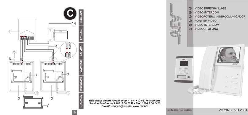
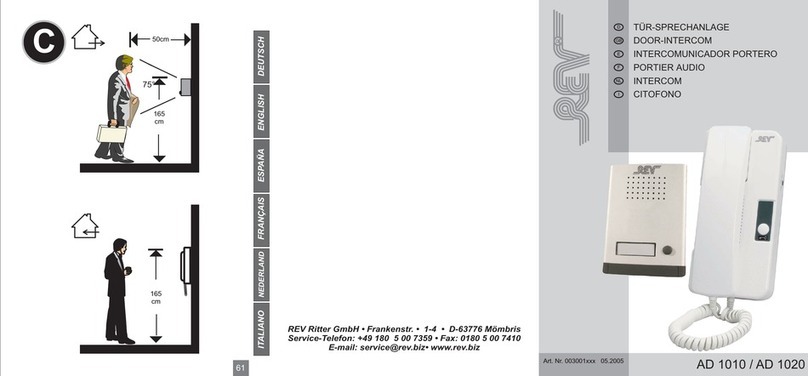
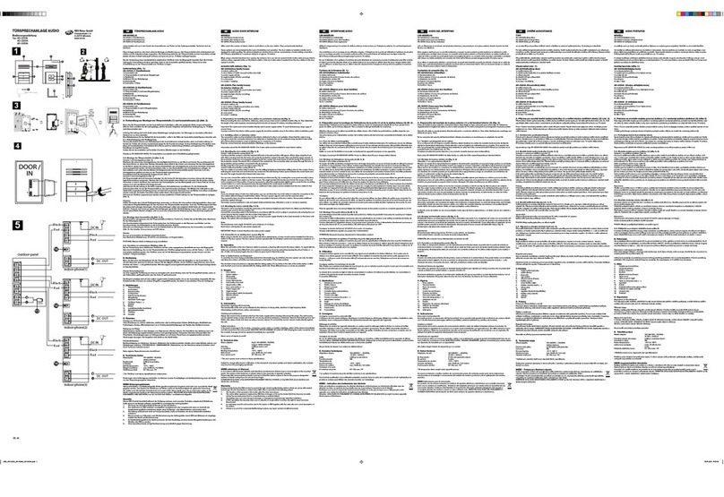
1. Gerätebeschreibung (Abbildung: siehe letzte Seite)
INNENSTATION
Hörer
1) Lautsprecher
2) Batteriekontroll-LED
3) Sprechtaste
a. Nach dem Klingeln einmal die Sprechtaste drücken. Dann kann mit dem Besucher
gesprochen werden.
b. Ein weiterer Druck auf die Sprechtaste beendet das Gespräch.
4) Türöffner-Taste
a. Während des Gesprächs die Türöffner-Taste für mindestens 1 Sekunde drücken, um den
Türöffner zu aktivieren (ist im Standby-Modus nicht möglich).
5) Batteriekontroll-LED für die Außensprechstelle
Ladestation
6) Buchse für den Netzadapter.
AUSSENSTATION
Außen-Sprechstelle
7) Lautsprecher
8) Klingeltaster und Namensschild
9) Kontroll-LED
10) Schraubenloch für die Installation
11) Mikrofon
Powerbox
12) Batteriekontroll-LED
13) Befestigungslöcher
14) Kabelausgang für Türöffner und Klingeltransformator
15) Reset-Taster
16) Lithium-Polymer-Akku
2. Funktionen und Technische Details
•2.4 GHz - Digitale Funk-Technik
•Sehr gute Klangqualität
•Codierung wechselbar (keine Überschneidung mit ähnlichen Geräten)
•Sicherheit durch AFH-Funktion (Adaptive Frequency Hopping)
•Türöffner-Funktion
•Wieder aufladbare Lithium-Polymer Akkus
•Batterie-Überwachung
•Geringer Stromverbrauch
SPEZIFIKATIONEN INNEN- UND AUSSENSTATION
•Sendefrequenz: 2.400~2.479 GHz
•Sendeleistung: 20 dBm
•Modulationsart: GFSK
•Frequenzauswahlverfahren: AFH (Adaptive Frequency Hopping)
•Empfangsempfindlichkeit: -100 dBm
DD

3
•Reichweite: 200 m (Freifeld)
•Stromversorgung Innenstation: Akku (Lithium-Polymer) 3.7V / 500 mAh
•Stromversorgung Außenstation: Akku (Lithium-Polymer) 3.7V / 4000 mAh
•Stromaufnahme Innenstation: Standby = 25 mW In Betrieb = 120 mW
•Stromaufnahme Außenstation: Standby = 1 mW In Betrieb = 1 W
•Betriebstemperatur: -20° bis +50° C
•Lagertemperatur: -40° bis +85° C
•Batterieüberwachung: Power LED's blinken
•Türöffnerfunktion: Potentialfreier Schaltkontakt
SPEZIFIKATIONEN LADESTATION
•Stromversorgung: DC 9V 300 mA
•Ausgangsspannung / Strom: 4.2V 500 mA
•Maximaler Ladestrom: 500 mA max.
•Ladeschlussspannung: 4.2V
•Ladezeit: 3 Stunden (Inneneinheit) / 12 Stunden (Außeneinheit)
•Betriebstemperatur: -20° bis +50°C
•Lagertemperatur: -40° bis +85°C
•Überladeschutz-Spannung: 4,25 V
•Entladeschutz-Spannung: 3,2 V
3. Installation
INNENEINHEIT
Schritt 1: Nehmen Sie die Ladestation, den Hörer und das Netzteil aus der Verpackung.
Schritt 2: Verbinden Sie das Netzteil mit der Ladestation, stecken Sie den Stecker dazu in die
Buchse an der Ladestation (6).
Schritt 3: Stellen Sie den Hörer in die Ladestation.
Hinweis: Ist der Akku komplett leer, dauert der Ladevorgang ca. 3 Stunden.
AUSSENEINHEIT
Powerbox:
Schritt 1: Nehmen Sie die Powerbox aus der Verpackung.
Schritt 2: Suchen Sie sich einen Platz aus, an dem Sie die Powerbox montieren können
(vorzugsweise gegenüber der Außen-Sprechstelle).
Schritt 3: Bohren Sie anhand der Bohrschablone die Löcher (Ø 6mm) in die Wand und stecken
Sie die mitgelieferten Dübel hinein.
Schritt 4: Schrauben Sie die Schrauben soweit in die Dübel, dass die Schraubenköpfe noch ca.
2-3 mm aus der Wand herausschauen.
Bitte entfernen Sie vor der Installation den Akku in der POWERBOX.
Bei der Montage bzw. Durchführung der Kabel durchs Mauerwerk könnten die offenen
Kabelenden sich berühren und es zu einem Kurzschluss im Akku kommen.
Ferner empfehlen wir Ihnen den Akku in der POWERBOX (ca.10 Std.) und im Mobilteil (ca. 3
Std.) vor der Inbetriebnahme vollständig aufzuladen.
Außerdem wird empfohlen, sich die Kabelbelegung der 6-adrigen Leitung zwischen Außen-
Sprechstelle und Powerbox zu notieren, bevor Sie diese zur Installation lösen.

4
Anschluss eines Türöffners
Um einen Türöffner mit dieser Anlage schalten zu können, besitzt sie an der Powerbox einen
potentialfreien Schaltkontakt. Dieser ist mit den beiden blauen Leitungen aus der Powerbox
heraus geführt. Wie der Türöffner angeschlossen wird, entnehmen Sie bitte dem angefügten
Schaltplan (siehe letzte Seite) für Türöffneranschluss. Da für den Türöffner ein Klingel-
transformator erforderlich ist, können Sie die Powerbox auch über diesen Klingeltransformator mit
Strom versorgen. An den beiden roten Anschlussleitungen kann eine Wechselspannung von ca.
8-10 Volt angeschlossen werden. Der Akku muss in diesem Fall entnommen werden. Auf korrekte
Polung braucht nicht geachtet zu werden.
ACHTUNG, EXPLOSIONSGEFAHR! Bei Anschluss eines Klingeltrafos muss der Akku aus dem
Gerät entfernt werden.
Außen-Sprechstelle (nur für Unterputzmontage geeignet):
Schritt 1: Suchen Sie sich einen geeigneten Standort für die Außensprechstelle.
Schritt 2: Stemmen oder sägen Sie an dieser Stelle ein Loch mit folgenden Abmessungen in die
Wand: 130 mm (Höhe)*100 mm (Breite)*40 mm (Tiefe)
Schritt 3: Montieren Sie die Unterputzdose von der Außen-Sprechstelle ab, indem Sie die untere
Schraube herausschrauben und das Vorderteil vorsichtig nach oben schieben und
dabei etwas hin und her bewegen.
Hinweis: Die 6-adrige Leitung kann ganz einfach durch Drücken auf die Klemmen gelöst
werden.
Schritt 4: Namensschild anpassen:
1. Entfernen Sie die beiden Schrauben, die die Platine festhalten.
2. Nehmen Sie die Platine beiseite, um das Namenschild freizulegen.
a) Nehmen Sie das Namensschild heraus und schreiben Sie Ihren Namen auf das
weiße Stück Papier.
b) Montieren Sie die Außensprechstelle wieder, indem Sie die Schritte 1 und 2 in
umgekehrter Reihenfolge wiederholen.
Schritt 5: Richten Sie die Unterputzdose aus und fixieren Sie sie mit zwei Schrauben in dem in
die Wand gestemmten Loch.
Schritt 6: Die verschiedenfarbigen Adern der Verbindungsleitung anhand der Farbcodierung mit
der Anschlussklemme der Außen-Sprechstelle verbinden. Die Leitung kann individuell
gekürzt werden.
Schritt 7: Hängen Sie die Außen-Sprechstelle in die Unterputzdose und schrauben Sie die
Befestigungsschraube in das dafür vorgesehene Loch, um die Außen-Sprechstelle
wieder auf der Unterputzdose zu fixieren.
Schritt 5: Bohren Sie ein ca. 8 mm großes Loch durch die Wand zur Außen-Sprechstelle und
schieben Sie die Verbindungsleitung hindurch. Versiegeln Sie das Loch anschließend,
z.B. mit Silikon.
Schritt 6: Hängen Sie die Powerbox mit den Befestigungslöchern auf die Schrauben.
HINWEIS: Um die Leitung von der Außen-Sprechstelle nicht sichtbar verlegen zu müssen, bohren
Sie das Loch für die Leitungsdurchführung vorzugsweise direkt hinter der Powerbox durch die
Wand. Wird die Außen-Sprechstelle direkt gegenüber montiert, ist der Aufwand am geringsten.
Wählen Sie den Standort der Powerbox am besten danach aus.

4.4. Batteriekontrolle
a. Außen-Sprechstelle: Wenn derAkku leer ist, sendet dieAußenstation ein Signal zum Hörer.
Dadurch blinkt am Hörer die LED (5), und gleichzeitig blinkt die Batteriekontroll-LED (12) an
der Powerbox schnell.
b. Hörer: Wenn derAkku leer ist, blinkt die LED (2) schnell.
5
5. Im Standby-Modus
a. Außen-Sprechstelle: Im Standby-Modus ist die LED (9) aus.
b. Hörer: Im Standby-Modus blinkt die LED (2) alle 5 Sekunden einmal.
6. In Betrieb
a. Außen-Sprechstelle: Wird der Klingeltaster gedrückt, gibt die Außen-Sprechstelle einen
Freizeichenton ab. Wenn niemand das Gespräch mit dem Hörer annimmt, schaltet sich die
Außen-Sprechstelle nach ca. 30 Sekunden wieder in den Standby-Modus. Nimmt jemand das
Gespräch an, verstummt der Ton und es kann mit der Inneneinheit gesprochen werden.
Ist der Hörer ausgeschaltet, gibt die Außen-Sprechstelle einen “Di-Di-Di-Di”-Ton ab und geht
wieder in den Standby-Modus.
b. Hörer: Wenn der Hörer das Klingelsignal empfängt, leuchtet die LED (2) dauerhaft und die
eingestellte Melodie ertönt. Wenn niemand das Gespräch annimmt, verstummt die Melodie
nach ca. 30 Sekunden und der Hörer geht wieder in den Standby-Modus. Wird während dieser
30 Sekunden die Sprechtaste (3) gedrückt, stoppt die Melodie und es kann mit der Außen-
Sprechstelle gesprochen werden.
c. Türöffner: Möchten Sie den Türöffner aktivieren, drücken Sie während des Gesprächs auf die
Türöffnertaste (4) und halten Sie diese für mindestens 2 Sekunden gedrückt.
d. Durch erneutes Drücken der Sprechtaste (3) wird die Verbindung getrennt und die Innenstation
geht wieder in den Standby-Modus.
HINWEIS: Der Türöffner kann nur während des Gespräches aktiviert werden.
7. Bei fehlerhafter Verbindung
a. Wenn der Klingeltaster gedrückt wird und dieAußen-Sprechstelle innerhalb von 2 Sekunden
keine Verbindung zum Hörer aufbauen kann (entweder außerhalb der Reichweite oder
ausgeschaltet), gibt die Außen-Sprechstelle einen “Di-Di-Di-Di”-Ton ab und schaltet sich wieder
aus.
b. Ist die Verbindung zustande gekommen, aber das Signal reißt ab, dann geben Hörer und
Außen-Sprechstelle einen “Di”-Ton ab und Hörer sowie Außen-Sprechstelle schalten wieder in
ihren Standby-Modus.
4. Inbetriebnahme
4.1. Einschalten des Hörers
Durch Stellen des Hörers in die Ladestation oder durch gleichzeitiges Drücken der Sprech- (3)
und Türöffnertaste (4) für mindestens 6 Sekunden.
4.2. Ausschalten des Hörers
Durch gleichzeitiges Drücken der Sprech- (3) und Türöffnertaste (4) für mindestens 8 Sekunden.
Die LED (2) blinkt einmal.
4.3. Codierung einstellen (nur im Falle einer Fehlfunktion notwendig):
Drücken Sie gleichzeitig die Reset-Taste (15) und den Klingeltaster (8) an der Außen-Sprechstelle
und der Powerbox. Dann drücken und halten Sie die Türöffnertaste (4) am Hörer für 3 Sekunden
(im Standby-Modus). Nach erfolgreicher Codierung gibt der Hörer einen “DI-DI”-Ton ab und die
LED (2) am Hörer sowie die LED (9) an der Außen-Sprechstelle blinken zweimal.

6
Powerbox:
1) Öffnen Sie die Powerbox und entnehmen Sie den Akku (16), indem Sie den Stecker
herausziehen und dann den vordersten Clip leicht nach vorne drücken.
2) Stecken Sie den Stecker des Akkus in die Ladestation. Bild (17) und schließen Sie den
Netzadapter an.
3) Nach ca. 10 Stunden ist der Ladevorgang abgeschlossen.
Garantie
Dieses REV-Produkt durchläuft während der Fertigung mehrere, nach neuesten Techniken
aufgebaute Prüfstationen. Sollte dennoch ein Mangel auftreten, leistet REV im nachfolgenden
Umfang Gewähr:
1. Die Dauer der Garantie beträgt 24 Monate ab dem Kaufdatum.
2. Das Gerät wird von REV entweder unentgeltlich nachgebessert oder ausgetauscht, wenn es
innerhalb der Gewährleistungspflicht nachweisbar wegen eines Fertigungs- oder
Materialfehlers unbrauchbar wird.
3. Die Haftung erstreckt sich nicht auf Transportschäden sowie auf Schäden, die durch fehlerhafte
Installation entstehen.
4. Wird innerhalb von 6 Monaten nach Nichtanerkennung des Haftungsfalles durch REV kein
Widerspruch eingelegt, verjährt das Recht auf Nachbesserung.
5. Im Gewährleistungsfall ist das Gerät zusammen mit dem Kaufbeleg und einer kurzen
Mängelbeschreibung an den Händler oder REV zu senden.
6. Ohne Garantienachweis erfolgt Nachbesserung ausschließlich gegen Berechnung.
WEEE-Entsorgungshinweis
Gebrauchte Elektro- und Elektronikgeräte dürfen gemäß europäischer Vorgaben nicht mehr zum
unsortierten Abfall gegeben werden. Das Symbol der Abfalltonne auf Rädern weist auf die
Notwendigkeit der getrennten Sammlung hin.
Helfen auch Sie mit beim Umweltschutz und sorgen dafür, dieses Gerät, wenn Sie es nicht mehr
nutzen, in die hierfür vorgesehenen Systeme der Getrenntsammlung zu geben.
RICHTLINIE 2002/96/EG DES EUROPÄISCHEN PARLAMENTS UND DES RATES vom 27.
Januar 2003 über Elektro- und Elektronik-Altgeräte.
DE 72368453
Die auswählbaren Melodien sind:
1. Romance De Amor 2. Beauty And The Beast 3. Memory
4. My Heart Will Go On 5. Music Box Dancer 6. Close To You
7. Close To My Heart 8. All For Love 9. Für Elise
10. Rhythm of the Rain Lyrics 11. Love is Bule 12. Romeo and Juliet
9. Akkus laden
Hörer:
1) Verbinden Sie die Ladestation mit dem Netzadapter.
2) Stellen Sie den Hörer in die Ladestation. Die LED (2) leuchtet während des Ladevorgangs
dauerhaft.
3) Nach 3 Stunden ist der Ladevorgang abgeschlossen.
8. Melodie des Hörers auswählen
Drücken und halten Sie die Sprechtaste (3), bis die eingestellte Melodie zu hören ist. Lassen die
Sprechtaste los. Durch kurzes Drücken der Sprechtaste wird eine Melodie weiter gesprungen. Um
eine Melodie auszuwählen, drücken Sie die Türöffner-Taste. Die gerade gespielte Melodie wird
gespeichert und beim nächsten Klingeln abgespielt.

7
Operating manual
PLEASE READ CAREFULLY TOAVOID INSTALLATION ERRORS.
1. Equipment description (Figure: see on last page)
INDOOR STATION
HANDSET
1) Loudspeaker
2) Battery check LED
3) Talk button
a. To talk to the visitor, push the talk button once after the bell rings.
b. End the conversation by pressing the talk button again.
4) Door opener button
a. Push the door opener button for at least 1 second during the conversation to activate the door
opener (not possible in standby mode).
5) Battery check LED for the outside station
CHARGING STATION
6) Socket for the AC adapter.
OUTSIDE STATION
Outside communication unit position
7) Loudspeaker
8) Bell button and nameplate
9) Control LED
10) Screw hole for installation
11) Microphone
Powerbox
12) Battery check LED
13) Mounting holes
14) Cable exit for door opener and bell transformer
15) Reset button
16) Lithium Polymerrechargeable battery
2. Functions and technical details
•2.4 GHz Digital radio technology
•Very high sound fidelity
•Coding interchangeable (no interference with similar equipment)
•Security by AFH function (Adaptive Frequency Hopping)
•Door opening function
•Rechargeable Lithium Polymer batteries
•Battery monitoring
•Low power consumption
SPECIFICATIONS INSIDE AND OUTSIDE STATIONS
•Transmitting frequency: 2.400~2.479 GHz
•Transmitter power: 20 dBm
•Modulation type: GFSK
•Frequency selection method: AFH (Adaptive Frequency Hopping)
•Receiver sensitivity: -100 dBm
GBGB

8
•Range: 200 m (open field)
•Power supply inside station: Battery (Lithium Polymer) 3.7V / 500 mAh
•Power supply outside station: Battery (Lithium Polymer) 3.7V / 4000 mAh
•Power consumption inside station: Standby = 25 mW operating = 120 mW
•Power consumption outside station: Standby = 1 mW operating = 1 W
•Operating temperature: 20° to +50° C
•Storage temperature: -40° to +85° C
•Battery monitoring: Power LED's flashing
•Door opening function: Floating relay contacts
SPECIFICATIONS CHARGING STATION
•Power supply: DC 9V 300 mA
•Output voltage / current: 4.2V 500 mA
•Maximum charging current: 500 mA max.
•Max. charging voltage: 4.2V
•Charging time: 3 hours (inside unit) / 12 hours (outside unit)
•Operating temperature: 20° to +50°C
•Storage temperature: -40° to +85°C
•Overload protection voltage: 4.25 V
•Discharge protection voltage: 3.2 V
3. Installation
INSIDE UNIT
Step 1: Unpack the charging station, handset and AC adapter.
Step 2: Connect the adapter to the charging station by inserting the plug into the socket on
the charging station (6).
Step 3: Place the handset in the charging station.
Note: If the battery is totally empty, the charging cycle takes about 3 hours.
OUTSIDE UNIT
Powerbox:
Step 1: Remove the Powerbox from the packaging.
Step 2: Find a place where you can mount the Powerbox (preferably opposite the outside
communication unit).
Step 3: Use the drilling template to drill the holes (Ø 6mm) into the wall and insert the plugs
provided.
Step 4: Screw the screws into the plugs until the screw heads project 2 3 mm from the wall.
Please delete before installation the rechargeable battery inside POWERBOX.
During installation the open end of the wires could be touched which effects that the
rechargeable battery could be destroyed.
Further we suggest to fully charge the rechargeable battery in the POWERBOX for 10 hours
and the rechargeable battery of the mobile-unit for 3 hours, before using.
Furthermore we suggest to make a note of the assignment of the 6-core lead between
outside unit and Powerbox, before you remove for assembly.

9
Connecting a door opener
The Powerbox has a floating relay contact for operating a door opener using this system. The
connection is available on the outside of the Powerbox via the two blue leads. Please refer to the
included diagram (see on last page) for the door opener connection for information on how to
connect the door opener. Since the door opener requires a bell transformer, you can also supply
power to the Powerbox via this bell transformer.
AC voltage of about 8-10 Volt can be connected to the two red terminals. In this case, the battery
must be removed. Polarity is irrelevant.
WARNING, EXPLOSION HAZARD! The battery must be removed from the equipment when a
bell transformer is connected.
Outside communication unit (suitable for mounting under the plaster only):
Step 1: Find a suitable place for the outside communication unit.
Step 2: In this position, chisel or saw a hole into the wall with the following dimensions: 130 mm
(height)*100 mm (width)*40 mm (depth)
Step 3: Remove the under-plaster box from the outside communication unit by removing
the ower screw and carefully pushing the front part upwards, gently moving to and fro.
Note: The 6-core lead can easily be removed by pressing on the terminals.
Step 4: Mark the name tag:
1. Remove the two screws holding the cover plate.
2. Remove the cover to expose the name tag.
a) Remove the name tag and write your name on the white piece of paper.
b) Fit the outside communication unit again by repeating steps 1 and 2 in reverse
order.
Step 5: Align the under-plaster box and fasten in the hole chiselled into the wall using the two
screws.
Step 6: Connect the different coloured cores of the connecting lead in accordance with the
colour codes to the connecting terminals of the outside communication unit. The cores
can be individually shortened.
Step 7: Hang the outside communication unit in the under-plaster box and screw the fixing screw
into the hole provided to affix the outside communication unit to the under-plaster box
again.
4. Operating
4.1. Switching on the handset
Place the handset in the charging station or simultaneously press the talk (3) and door opening (4)
buttons for at least 6 seconds.
4.2. Switching off the handset
Simultaneously press the talk (3) and door opening (4) buttons for at least 8 seconds. The LED
(2) flashes once.
Step 5: Drill an approx. 8mm hole through the wall to the outside communication unit and thread
the connecting wire through the hole. Then seal the hole using e.g. silicon.
Step 6: Hang the Powerbox from the screws, using the attachment holes.
NOTE: To hide the lead to the outside communication unit, preferably drill the hole for the lead
through the wall directly behind the Powerbox. Minimise the effort by fitting the outside
communication unit directly opposite. Try to select the position of the Powerbox accordingly.

4.3. Set coding (only required in case of errors):
Simultaneously press the Reset button (15) and the Bell button (8) on the outside communication
unit and the Powerbox. Then press and hold the door opening button (4) on the handset for 3
seconds (in standby mode). The handset emits a “DEE-DEE” sound after successful coding and
the LED (2) on the handset and LED (9) on the outside communication unit flash twice.
4.4. Battery control
a. Outside communication unit: When the battery is flat, the outside station sends a signal to the
handset. This causes the LED (5) on the handset and the battery check LED (12) on the
Powerbox to flash fast.
b. Handset: When the battery is flat, LED (2) flashes fast.
10
5. In standby mode
a. Outside communication unit: LED (9) is off in the standby mode.
b. Handset: LED (2) flashes once every 5 seconds in standby mode.
6. In Operation
a. Outside communication unit: When the bell button is pressed, the outside communication unit
emits a dialling tone. If no one accepts the call with the handset, the outside communication
unit reverts to standby mode after about 30 seconds. If the call is accepted, the tone is silent
and you can talk to the inside unit.
If the handset is switched off, the outside communication unit emits a “Dee-Dee-Dee-Dee”
sound and reverts to standby mode.
b. Handset: When the handset receives the ring tone, LED (2) lights up and the set tune is
played. If the call is not answered, the tune stops after about 30 seconds and the handset
reverts to standby mode. If the talk button (3) is pressed within these 30 seconds, the tune
stops and you can talk to the outside unit.
c. Door opener: To activate the door opener, push the door opener button (4) and hold down for at
least 2 seconds during the conversation.
d. The connection is broken by again pushing the talk button (3) - the inside station reverts to
standby mode.
NOTE: The door opener can only be activated during the conversation.
7. Wrong connection
a. If the ring button is pushed and the outside communication unit cannot make a connection to
the handset within 2 seconds (either outside of range or switched off), the outside
communication unit emits a “Dee-Dee-Dee-Dee” tone and switches off again.
b. If a connection is established, but the signal then disappears, the handset and outside
communication unit emit a “Dee” tone and both handset and outside communication unit switch
back to standby mode.
8. Choose handset tune
Push and hold down the talk button (3) until you hear the set tune. Release the talk button. Skip
tunes by briefly pressing the talk button. To select a tune, press the door opening button. The tune
just played is saved and played again when the bell rings.
The available tunes are:
1. Romance De Amor 2. Beauty And The Beast 3. Memory
4. My Heart Will Go On 5. Music Box Dancer 6. Close To You
7. Close To My Heart 8. All For Love 9. Für Elise
10. Rhythm of the Rain Lyrics 11. Love is Bule 12. Romeo and Juliet

11
Powerbox:
1) Open the Powerbox and remove the battery (16) by removing the plug and then gently
pressing the front clip forward.
2) Plug the battery plug into the charging station.
3) Charging is complete after about 10 hours.
Warranty
During manufacturing this REV product is passed through several quality testing stations which
are set up with newest technology. Should nevertheless a defect arise, REV offers a warranty to
the following extent:
1. The duration of the warranty is 24 months after the date of purchase.
2. The unit is either repaired or replaced by REV free of charge or if it can be shown that it has
Become unusable during the warranty period due to a manufacturing or material defect.
3. The liability does not cover transport damages or damaged incurred through defective
installation.
4. If REV repudiates the warranty claim and no objection is made within 6 months, the right to
repair becomes time-barred.
5. In a warranty case the unit must be sent to the dealer or REV together with the sales slip and
a short description of the defect.
6. If there is no proof for a warranty liability being in place, any repair carried out will be invoiced.
Garantie
WEEE-reference of disposal
In accordance with European defaults used electrical and electronics devices may no more be
given to the unsorted waste. The symbol of the waste bin on wheels refers to the necessity of
separate collection.
Please help with environmental protection and see to it that this device is given
to the for this purpose designated systems of waste sorting if you do not use it any longer.
GUIDELINE 2002/96/EG of the EUROPEAN PARLIAMENT AND the COUNCIL of January 27th
2003 about electrical and electronics old devices.
DE 72368453
9. Charging batteries
Handset:
1) Connect the charging station to the AC adapter.
2) Place the handset in the charging station. LED (2) lights up during the charging process.
3) Charging is complete after 3 hours.

12
Mode d'emploi
VEUILLEZ LISEZ ATTENTIVEMENT CE MODE D'EMPLOI AFIN D'EVITER TOUTE ERREUR DE
MONTAGE.
1. Description de l'appareil (Photo: voir dernière page)
STATION INTERIEURE
Interphone extérieur
1) Haut-parleur
2) LED de contrôle de la batterie
3) Touche parole
a. Après la sonnerie, appuyez une fois sur la touche parole. Vous pouvez alors parler au
visiteur.
b. Un nouvel appui sur la touche parole interrompt la conversation
4) Touche d'ouverture de la porte.
a. Lors de la conversation, appuyez sur la touche d'ouverture de la porte pendant au moins 1
seconde afin d'activer le système d'ouverture de la porte (ceci n'est pas possible en mode
veille).
5) LED de contrôle de la batterie de l'interphone extérieur.
STATION DE RECHARGEMENT
6) Prise pour l'adaptateur secteur.
STATION EXTERIEURE
Interphone extérieur
7) Haut-parleur
8) Bouton de sonnette avec porte-nom
9) LED de contrôle
10) Trou de vissage pour l'installation
11) Microphone
Powerbox
12) LED de contrôle de la batterie
13) Trous de fixation
14) Sortie de câble pour le système d'ouverture de la porte et le transformateur de la sonnette
15) Touche de réinitialisation
2. Fonctions et details techniques
•Technologie digitale sans fil 2,4 GHz
•Excellente qualité sonore
•Codage modifiable (aucune interférence avec les appareils similaires)
•Sécurité grâce à la fonction AFH (Adaptive Frequency Hopping)
•Fonction ouverture de porte
•Batteries lithium-polymère rechargeables
•Contrôle de la batterie
•Consommation électrique faible
SPECIFICATIONS STATIONS INTERIEURE ET EXTERIEURE
•Fréquence d'émission: 2400~2479 GHz
•Puissance d'émission: 20 dBm
•Type de modulation: GFSK
•Processus de sélection de la fréquence: AFH (Adaptive Frequency Hopping)
•Sensibilité de réception: -100 dBm
FF

13
•Portée: 200 m (sans obstacles)
•Alimentation station intérieure: Batterie (lithium-polymère) 3,7 V / 500 mAh
•Alimentation station extérieure: Batterie (lithium-polymère) 3,7 V / 4000 mAh
•Consommation électrique station intérieure: Mode veille = 25 mW En fonctionnement = 120 mW
•Consommation électrique station extérieure Mode veille = 1 mW En fonctionnement = 1 mW
•Température de service: -20° à +50°C
•Température de stockage: -40° à +85°C
•Surveillance de la batterie: Les LED « Power » clignotent
•Fonction d'ouverture de la porte: Contact de commutation de commande libre de potentiel
SPECIFICATIONS STATION DE CHARGEMENT
•Alimentation: CC 9 V 300 mA
•Tension de sortie / Electricité: 4,2 V 500 mA
•Courant de charge maximal: max. 500 mA
•Tension finale de charge: 4,2 V
•Temps de charge: 3 heures (unité intérieure) / 12 heures (unité extérieure)
•Température de service: -20° à +50°C
•Température de stockage: -40° à +85°C
•Tension de protection contre la surcharge: 4,25 V
3. Installation
UNITE INTERIEURE
Etape 1: déballez la station de chargement, le combiné et l'adaptateur secteur.
Etape 2: reliez l'adaptateur secteur avec la station de chargement. Pour ce faire, connectez la
fiche dans la prise de la station de chargement (6).
Etape 3: placez le combiné sur la station de chargement.
Indication:lorsque la batterie est entièrement vide, le processus de charge dure environ 3 heures.
UNITE EXTERIEURE
Powerbox
Etape 1: retirez la Powerbox de l'emballage.
Etape 2: cherchez un endroit où vous pourrez fixer la Powerbox (idéalement en face de
l'interphone extérieur)
Etape 3: à l'aide du gabarit de forage, percez les trous (Ø 6 mm) dans le mur et placez-y les
chevilles fournies.
Etape 4: vissez les vis dans les chevilles de sorte que les têtes de vis soient encore uniquement
visibles sur 2 à 3 mm.
Etape 5: forez un trou d'environ 8 mm à travers le mur afin de rejoindre l'interphone extérieur et
passez-y le câble de connexion. Scellez ensuite le trou, par exemple avec de la
silicone.
Etape 6: placez la Powerbox en posant les trous de fixation au niveau des vis.
INDICATION: afin que le câble de l'interphone extérieur ne soit pas visible, forez de préférence le
trou dans lequel il doit passer directement derrière la Powerbox. Le montage le plus simple est de
fixer l'interphone extérieur directement en face de la Powerbox. Sélectionnez le meilleur endroit
possible pour la Powerbox en conséquence.

Raccordement du système d'ouverture de porte
Afin de pouvoir connecter un système d'ouverture de porte à cette installation, la Powerbox est
équipée d'un contact de commutation de commande libre de potentiel. Ce dernier est amené vers
l'extérieur au moyen des deux câbles bleus. Consultez le plan de connexion (voir dernière page)
d'un système d'ouverture de porte annexé afin de savoir comment raccorder le système
d'ouverture de porte. Le système d'ouverture de porte nécessitant un transformateur de sonnette,
il est également possible d'alimenter la Powerbox en électricité via ce transformateur de sonnette.
Les deux câbles de connexion rouges peuvent être raccordés à un courant alternatif d'environ 8 à
10 volts. Dans ce cas, il est nécessaire de retirer la batterie. Il n'est pas nécessaire de tenir
compte de la polarité.
ATTENTION, RISQUE D'EXPLOSION! Lors de la connexion d'un transformateur de sonnette, la
batterie doit être retirée de l'appareil.
Interphone extérieur (uniquement pour montage encastré):
Etape 1: choisissez un endroit approprié pour l'installation de l'interphone extérieur.
Etape 2: mortaisez ou sciez un trou des dimensions suivantes à cet endroit du mur: 130 mm
(hauteur)*100 mm (largeur)* 40 mm (profondeur)
Etape 3: démontez la boîte encastrable de l'interphone extérieur en dévissant la vis inférieure
et en tirant ensuite précautionneusement la partie avant vers le haut tout en faisant
quelques mouvements de va-et-vient.
Indication:le câble à 6 fils se détache simplement par un appui sur les bornes.
Etape 4: adaptation du porte-nom :
1. retirez les deux vis qui maintiennent la plaque.
2. retirez la plaque afin d'accéder au porte-nom.
a) retirez le porte-nom et inscrivez votre nom sur le morceau de papier blanc.
b) remontez l'interphone extérieur en répétant les étapes 1 et 2 dans l'ordre inverse.
Etape 5: ajustez la boîte d'encastrement et fixez-la dans les trous mortaisés dans le mur à cet
effet à l'aide de deux vis.
Etape 6: connectez les fils de différentes couleurs du câble de raccordement en respectant le
codage de couleurs à la borne de raccordement de l'interphone extérieur. Le câble
peut être raccourci individuellement.
Etape 7: placez l'interphone extérieur sur la boîte d'encastrement et vissez la vis de fixation
dans le trou prévu à cet effet afin de refixer l'interphone extérieur sur la boîte
d'encastrement.
14
4. Mise en service
4.1. Mise en marche du combiné
Par un appui simultané sur les touches parole (3) et ouverture de la porte (4) pendant au moins 6
secondes. Par le placement du combiné dans la station de chargement.
4.2. Arrêt du combiné
Par un appui simultané sur les touches parole (3) et ouverture de la porte (4) pendant au moins 8
secondes. La LED (2) clignote une fois.
4.3. Définition du codage (uniquement nécessaire lorsqu'une erreur survient):
Appuyez simultanément sur la touche réinitialisation (15) et sur la touche sonnette (8) de
l'interphone extérieur et de la Powerbox. Appuyez ensuite sur la touche d'ouverture de porte (4)
du combiné et maintenez-la enfoncée pendant 3 secondes (en mode veille). Lorsque le codage a
été réalisé avec succès, le combiné émet un « TUT-TUT » et la LED (2) du combiné ainsi que la
LED (9) de l'interphone extérieur clignotent deux fois.

4.4. Contrôle de la batterie
a. Interphone extérieur : lorsque la batterie est vide, la station extérieure envoie un signal au
combiné. Ceci fait clignoter la LED (5) du combiné et la LED de contrôle de la batterie (12) de
la Powerbox clignote aussi simultanément.
b. Combiné : lorsque la batterie est vide, la LED (2) clignote rapidement.
15
5. Mode Veille
a. Interphone extérieur : en mode veille la LED (9) est éteinte.
b. Combiné : en mode veille, la LED (2) clignote une fois toutes les 5 secondes.
6. En fonctionnement
a. Interphone extérieur : lors d'un appui sur la touche sonnette, l'interphone extérieur émet un
signal de ligne libre. Si personne ne décroche le combiné, l'interphone extérieur se remet
automatiquement en mode veille après environ 30 secondes. Si quelqu'un décroche, le son
s'arrête et l'on peut communiquer avec l'interphone extérieur. Si le combiné est désactivé,
l'interphone extérieur émet un « tut-tut-tut » et repasse en mode veille.
B. Combiné : lorsque le combiné reçoit le signal de la sonnette, la LED (2) s'allume de manière
permanente et la mélodie définie retentit. Si personne ne décroche le combiné, la mélodie
s'arrête après environ 30 secondes et le combiné repasse en mode veille. Si quelqu'un appuie
sur la touche parole (3) endéans ces 30 secondes, la mélodie s'arrête et l'on peut
communiquer avec l'interphone extérieur.
c. Système d'ouverture de porte : si vous souhaitez activer le système d'ouverture de porte,
appuyez deux fois sur la touche d'ouverture de porte (4) lorsque vous êtes en communication
et maintenez-la enfoncée pendant au moins 2 secondes.
d. Un nouvel appui sur la touche parole (3) met fin à la connexion et la station interne repasse en
mode veille.
INDICATION: le système d'ouverture de porte ne peut être activé qu'en cours de conversation.
7. En cas de mauvaise connexion
a. Si après un appui sur la touche sonnette, l'interphone extérieur ne peut établir de
communication avec le combiné endéans les 2 secondes (soit parce qu'il se trouve hors de
portée ou qu'il est éteint), l'interphone extérieur émet un « tut-tut-tut » et il s'éteint.
b. Si la connexion a eu lieu mais que le signal se perd, le combiné et l'interphone extérieur
émettent tous les deux un « tut » et le combiné ainsi que l'interphone extérieur repassent en
mode veille.
8. Selection de la melodie du combine
Appuyez sur la touche parole (3) et maintenez-la enfoncée jusqu'à ce que vous entendiez la
mélodie définie. Relâchez la touche parole. Un bref appui sur la touche parole vous permet de
passer à la mélodie suivante. Pour sélectionner la mélodie, appuyez sur la touche d'ouverture de
porte. La mélodie en cours est enregistrée et retentira lors de la prochaine sonnerie.
Les mélodies disponibles sont:
1. Romance De Amor 2. Beauty And The Beast 3. Memory
4. My Heart Will Go On 5. Music Box Dancer 6. Close To You
7. Close To My Heart 8. All For Love 9. Für Elise
10. Rhythm of the Rain Lyrics 11. Love is Bule 12. Romeo and Juliet
9. Chargement des batteries
Combiné:
1) Connectez la station de chargement à l'adaptateur secteur.
2) Placez le combiné sur la station de chargement. La LED (2) reste allumée en permanence lors
du processus de chargement.
3) Le processus de chargement est terminé au bout de 3 heures.

Powerbox
1) Ouvrez la Powerbox et retirez la batterie (16). Pour ce faire, tirez la prise et appuyez ensuite le
clip avant légèrement vers l'avant.
2) Branchez la prise de la batterie dans la station de chargement.
3) Le processus de chargement est terminé au bout de 10 heures.
16
Garantie
Les produits REV subissent plusieurs contrôles en cours de fabrication, réalisés selon les
techniques les plus récentes. Si ce produit s'avérait toutefois être défectueux, REV assure une
garantie selon les conditions suivantes :
1. La durée de la garantie est de 24 mois à partir de la date d'achat.
2. L'appareil sera remis en état ou remplacé gratuitement si, pendant la durée de la garantie, il
s'avère inutilisable à cause d'un défaut matériel ou de fabrication.
3. Cette garantie ne couvre pas les dommages survenus pendant le transport ou suite à une
installation défectueuse.
4. Le droit à une remise en état est périmé si aucune réclamation n'est présentée dans les 6
Mois suivant un refus de reconnaissance de la garantie par notre société.
5. En cas de retour sous garantie, prière de faire parvenir l'appareil accompagné de la preuve
d'achat et d'une brève description du défaut à votre revendeur ou directement à REV.
6. Sans preuve de garantie, toute remise en état fera l'objet d'une facturation.
Garantie
WEEE - Indication des traitements des déchets
Suite aux indications européennes, les déchets électriques et électroniques ne doivent plus être
jeter avec les déchets non tirés. Le symbole de la poubelle avec les roues indique l'importance du
tri sélectif.
Participez vous aussi au respect de l'environnement et faites en sorte que, lorsque vous
n'utiliserez plus votre appareil, vous suiviez les indications du traitement des déchets.
Directive : 2002/96/EG DU PARLEMENT ET CONSEIL EUROPÉENS DU 27 janvier 2003 au sujet
d'anciens appareils électroniques et électriques.
DE 72368453

17
Návod k použití
PEČLIVĚ PROSÍM PŘEČTĚTE, ABYSTE SE VYVAROVALI CHYB PŘI MONTÁŽI
1. Popis přístroje
VNITŘNÍ STANICE
Sluchátko
1) Reproduktor
2) LED kontrolka baterie
3) Tlačítko hovoru
4) Tlačítko otevírání dveří
5) LED kontrolka baterie pro vnější hlasovou jednotku
Nabíjecí stanice
6) Zdířka pro síťový adaptér
VNĚJŠÍ STANICE
Vnější hlasová jednotka
7) Reproduktor
8) Zvonkové tlačítko a jmenovka
9) LED kontrolka
10) Otvor pro šroub pro instalaci
11) Mikrofon
Power box
12) LED kontrolka baterie
13) Připevňovací otvory
14) Vývod kabelu pro tlačítko otevírání dveří a zvonkový transformátor
15) Tlačítko reset
16) Lithium-polymerový akumulátor
2. Funkce a technické detaily
•Odběr proudu vnitřní stanice: Standby ? 25 mW V provozu ? 120 mW
•Odběr proudu vnější stanice: Standby ? 1 mW V provozu ? 1 W
3. Instalace
VNITŘNÍ JEDNOTKA
Krok 1: Připojte síťový zdroj na nabíjecí stanici, za tímto účelem zasuňte zástrčku do zdířky
na nabíjecí stanici (6).
Krok 2: Zasuňte sluchátko do nabíjecí stanice.
Upozornění: Pokud je akumulátor kompletně vybitý, proces nabíjení trvá cca 3 hodiny.
VNĚJŠÍ STANICE
Power box:
Krok 1: Najděte místo, na němž můžete nainstalovat power box (přednostně naproti vnější
hlasové jednotce).
Krok 2: Provrtejte stěnou směrem k vnější hlasové jednotce otvor velký cca 8 mm a
prostrčte jím spojovací vedení. Následně otvor zaplňte, např. silikonem.
Připojení tlačítka otevírání dveří
Pro účely zapínání tlačítka otevírání dveří pomocí tohoto zařízení je na power boxu umístěn
beznapěťový spínací kontakt. Ten je z power boxu vyveden pomocí dvou modrých kabelů. Způsob
připojení tlačítka otevírání dveří je uveden na přiloženém schématu připojení tlačítka otevírání
dveří. Protože tlačítko otevírání dveří vyžaduje zvonkový transformátor, můžete prostřednictvím
tohoto zvonkového transformátoru napájet elektrickým proudem rovněž power box.
Na obě červená přípojná vedení lze připojit střídavé napětí o cca 8-10 voltech. V takovém případě
musíte odpojit akumulátor. Nemusíte dávat pozor na správné připojení pólů.
CZCZ

POZOR, NEBEZPECÍ VÝBUCHU! Pri pripojení zvonkového transformátoru musíte akumulátor
odpojit od prístroje.
Vnejší hlasová jednotka (vhodná pouze pro montáž pod omítku):
Krok 1: Odmontujte krabici pod omítku od vnejší hlasové jednotky tím zpusobem, že
vyšroubujete spodní šroub a prední díl opatrne vysunete nahoru a pri tom jej trochu
posunete tam a zpet.
Krok 2: Ruznobarevné žíly spojovacího vedení s pomocí barevného kódování pripojte na
pripojovací svorku vnejší hlasové jednotky. Vedení mužete individuálne zkrátit.
18
4. Uvedení do provozu
4.1. Zapnutí sluchátka
Zasunutím sluchátka do nabíjecí stanice nebo současným tisknutím tlačítka hovoru (3) a tlačítka
otevírání dveří (4) po dobu minimálně 6 sekund.
4.2. Vypnutí sluchátka
Současným tisknutím tlačítka hovoru (3) a tlačítka otevírání dveří (4) po dobu minimálně 8
sekund. LED (2) jednou blikne.
4.3. Nastavení kódování (nezbytné pouze v případě chybného fungování):
Současně tiskněte tlačítko reset (15) a zvonkové tlačítko (8) na vnější hlasové jednotce a power
boxu. Poté stiskněte a držte stlačené tlačítko otevírání dveří (4) na sluchátku po dobu 3 sekund (v
režimu standby). Po úspěšném zakódování se ze sluchátka ozve tón “DI-DI” a LED (2) na
sluchátku a LED (9) na vnější hlasové jednotce dvakrát zabliká.
4.4. Kontrolka baterií
a. Vnější hlasová jednotka: Pokud je akumulátor vybitý, vyšle vnější stanice signál ke sluchátku.
Na základě tohoto signálu začne blikat LED (5) na sluchátku a zároveň začne rychle blikat i
LED kontrolka baterie (12) na power boxu.
b. Sluchátko: Pokud je akumulátor vybitý, začne rychle blikat LED (2).
5. V režimu standby
a. Vnější hlasová jednotka: V režimu standby je LED (9) vypnutá.
b. Sluchátko: V režimu standby LED (2) blikne jednou každých 5 sekund.
6. Nabití akumulátorů
Sluchátko:
1) Připojte nabíjecí stanici na síťový adaptér.
2) Zasuňte sluchátko do nabíjecí stanice. Během procesu nabíjení LED (2) trvale svítí.
3) Po 3 hodinách je proces nabíjení ukončen.
Power box:
1) Otevřete power box a vyjměte akumulátor (16) tím způsobem, že vytáhnete zástrčku a poté
přední svorku lehce stlačíte dopředu.
2) Zasuňte zástrčku akumulátoru do nabíjecí stanice obr. (17) a připojte síťový adaptér.
3) Po cca 10 hodinách je proces nabíjení ukončen.
WEEE Pokyny pro likvidaci odpadu
Podle evropských smernic již nesmejí být použité elektrické a elektronické prístroje odevzdávány
do netrídeného odpadu. Symbol popelnice na koleckách upozornuje na nezbytnost oddeleného
sberu.
Pomáhejte i Vy pri ochrane životního prostredí a postarejte se o to, aby byly tyto prístroje, pokud
je již nepoužíváte, odevzdány do systému oddeleného sberu urcených pro tyto úcely.
SMERNICE 2002/96/ES EVROPSKÉHO PARLAMENTU A RADY ze dne 27. ledna 2003 o
odpadních elektrických a elektronických zarízeních.
DE 72368453

19
Betjeningsvejledning
SKAL LÆSES OMHYGGELIGT FOR AT UNDGÅ MONTAGEFEJL
1. Beskrivelse af apparatet
INDESTATION
Hører
1) Højttaler
2) Batterikontrol-LED
3) Taletast
4) Døråbner-tast
5) Batterikontrol-LED til det udendørs samtaleapparat
Ladestation
6) Bøsning til netadapteren.
UDESTATION
Udendørs samtaleapparat
7) Højttaler
8) Ringetast og navneskilt
9) Kontrol-LED
10)Skruehul til installationen
11) Mikrofon
Powerboks
12) Batterikontrol-LED
13) Fastgørelseshuller
14) Kabeludgang for døråbner og ringetransformer
15) Reset-tast
16) Lithium-polymer-batteri
2. Funktioner og tekniske detaljer
•Strømforbrug indestation: Standby = 25 mW, under driften = 120 mW
•Strømforbrug udestation: Standby = 1 mW, under driften = 1 W
3. Installation
INDENDØRS ENHED
Skridt 1: Forbind netdelen med ladestationen. Hertil stikkes stikket ind i bøsningen på
ladestationen (6).
Skridt 2: Stil høreren i ladestationen.
Henvisning: Hvis batteriet er helt tomt, varer opladningen ca. 3 timer.
UDENDØRS ENHED
Powerboks:
Skridt 1: Find en plads, hvor De kan montere powerboksen (helst over for det udendørs
samtaleapparat).
Skridt 2: Bor et ca. 8 mm stort hul gennem væggen til det udendørs samtaleapparat og skub
forbindelsesledningen igennem. Forsegl derefter hullet, f.eks. med silikone.
Tilslutning af en døråbner
For at kunne aktivere en døråbner med dette anlæg har det en potentialfri kontakt på
powerboksen. Denne er ført ud af powerboksen med de to blå ledninger. I strømskemaet for
tilslutning af en døråbner kan De se, hvordan døråbneren tilsluttes. Da der kræves en
ringetransformer til døråbneren, kan De også forsyne powerboksen med strøm via denne
ringetransformer.
Der kan tilsluttes en vekselspænding på ca. 8-10 volt til de to røde tilslutningsledninger. Batteriet
skal i så fald tages ud. Det er ikke nødvendigt at sørge for, at polerne vender korrekt.
DKDK
Other REV Intercom System manuals