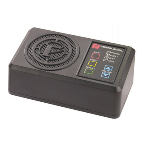
Federal Signal Corporation SELECTFONE SF-1245X-024 User manual

Address all communications and shipments to:
FEDERAL SIGNAL CORPORATION
Electrical Products Division
Service Department
2645 Federal Signal Drive
University Par , IL 60466-3195
MODEL SELECTFONE®
INSTRUCTION SHEET FOR FEDERAL
SELECTFONE


INSTRUCTION SHEET FOR FEDERAL SELECTFONE®
INTERCOM/PAGING SYSTEM
SAFETY NOTICES
WARNING
Failure to follow all safety precautions and instructions may result in property damage,
serious injury, or death to you or others.
SAFETY MESSAGE TO INSTALLERS, USERS, AND
MAINTENANCE PERSONNEL
I. GENERAL
The SelectFone® intercom and paging systems are designed for voice communication for indus-
trial environments where the communication equipment is installed in high-noise areas, corrosive
atmospheres, hazardous areas, and extremes of temperature, dust, and humidity. The intercom
system allows the operator to both page instructions over the 15-Watt, 8-Ohm spea ers and have
two-way conversations between two or more people on a telephone party line. With a five-chan-
nel intercom system multiple communication lin s can be established simultaneously without
cross tal or interference.
Ease of installation, simplified operation, simplified maintenance, unrestricted expansion, and
unshielded cable are some of the benefits of the Federal Signal SelectFone intercom system.
Typical installations include power plants, metal processing plants, mining operations, petroleum
and chemical plants, paper mills, water treatment facilities, and manufacturing, pac aging, and
processing plants.
A typical SelectFone intercom station features an impact resistant, Cycolac® handset with noise
canceling dynamic transmitter, and a receiver with a built-in push-to-page switch for one-hand
operation. The front panel of each unit features a handset cradle equipped with a contact-less
sensor to indicate an off-hoo condition, an ‘off-hoo ’ indicator LED, and channel selector switch
(on five-channel stations). In wall mount units, the 12-Watt paging amplifier, handset preampli-
fier, and power supply are enclosed in the housing. Des top and panel mount units are equipped
with the cables and connectors required to connect to the Remote Subset (within 10 feet), contain-
ing the paging amplifier, power supply, and handset amplifier. The amplifier and power supply
assemblies features a plug-in design for ease of installation and service. Each unit is equipped
with a terminal bloc for simplified installation.
II. SPECIFICATIONS
COMMON SPECIFICATIONS FOR ALL MODELS
Powe Requi ements
Operating voltage 105-130 VAC 50/60 Hz, 21 to 28 VDC (Nom. 24 VDC)
Standby Power Consumed 10 VA 120 VAC, 3 Watts 24VDC
Operating Power Consumed 33 VA 120 VAC, 28 Watts 24VDC max
Handset Amplifie
Output 1.5VRMS max. into 33 ohm load
Voltage Gain 68dB adjustable
Frequency Response 250-6500 Hz +/- 1.5dB
Distortion 2% THD max at 1000Hz
Controls Microphone Gain, Receiver Volume

Speake Amplifie
Output 12 Watts into 8 or 16 ohm load
Voltage Gain 31dB adjustable
Frequency Response 250-12000 Hz
Distortion Less than 2% THD at 12 Watt, 1000Hz
Input Impedance 50 ohm
Output Impedance 8 ohm or 16 ohm
Controls Spea er Volume Adjustable
Handset
Microphone 10 ohm dynamic noise canceling
Receiver 170 +/- 30 ohm high efficiency dynamic
Coil Cord 6 conductor, 10-ft extended
Agency App ovals
UL, cUL Models SF-1011DT, SF-1015DT, SF-1011P &
SF-1015P are listed for Class I, Div. 2 Grps. A, B, C &
D. Models SF-1231X, SF-1235X,
SF-1241X & SF-1245X are Listed for use in Class I,
Div. 2; Class II Div 2 Groups F and G, and Class III
Hazardous Locations
BASIC MODEL SPECIFICATIONS
III. INSTALLATION
SAFETY MESSAGE TO INSTALLERS
It is important to follow all instructions shipped with this product. This device is to be installed by a
trained electrician who is thoroughly familiar with the National Electrical Code and will follow the
NEC Guidelines as well as local codes.
The selection of the mounting location for the device, its controls, and the routing of the wiring is to be
accomplished under the direction of the facilities engineer and the safety engineer. In addition, listed
below are some other important safety instructions and
precautions you should follow:
• Read and understand all instructions before installing or operating this equipment.
• Disconnect power before connecting or doing any maintenance on this intercom.
Model Model Model Model Model Model Model Model
SF-1011P SF-1015P SF-1011DT SF-1015DT SF-1231X SF-1235X SF-1241X SF-1245X
Description 1 channel 5 channel 1 channel 5 channel 1 channel 5 channel 1 channel 5 channel
panel panel des top des top wall wall wall wall
mount mount mount mount mount mount
indoor indoor outdoor outdoor
Dimensions 9.5 x 7.86 9.5 x 7.86 9.5 x 7.86 9.5 x 7.86 N/A N/A N/A N/A
subset x 4 x 4 x 4 x 4
HxWxD in.
Dimensions 3.75 x 6.5 3.75 x 6.5 9.25 x 4.0 9.25 x 4.0 9.5 x 7.86 9.5 x 7.86 16.0 x 13.06 16.0 x 13.06
intercom x 6.0 x 6.0 x 9.0 x 9.0 x 7.7 x 7.7 x 8.5 x 8.5
HxWxD in.
Weight 16 lbs. 16 lbs. 16 lbs. 16 lbs. 10 lbs. 10 lbs. 19.0 lbs. 19.2 lbs.
-2-

• All effective paging spea ers produce loud sounds which may cause, in certain situations,
permanent hearing loss. You should ta e appropriate precautions such as wearing hearing
protection.
• After installation, ensure that all set screws are properly tightened.
• After installation, test the intercom to ensure that it is operating properly.
• After testing is complete, provide a copy of this instruction sheet to all operating personnel.
• Establish a procedure to routinely chec the light installation for integrity and proper operation.
Failu e to follow all safety p ecautions and inst uctions may esult in p ope ty damage, se ious
inju y, o death to you o othe s.
A. Unpacking
After unpac ing the unit, examine it for damage that may have occurred in transit. If the
equipment has been damaged, do not attempt to install or operate it, file a claim immediately
with the carrier stating the extent of the damage. Carefully chec all envelopes, shipping labels
and tags before removing or destroying them.
B. Installation Of Subset, Wall Station and Indoor/Outdoor Station Enclosure
(See Figure , 2)
The remote subset unit for panel mount and des top stations, the wall mount, and the indoor/
outdoor wall mount SelectFone stations use the same enclosure to house motherboard, plug-in
spea er amplifier, power supply etc. Only the front enclosure covers are different. The enclosures
are designed to be mounted on a flat surface with user-supplied hardware. As the locations of
SelectFone stations vary with each installation, these enclosures are not provided with conduit or
cable openings. To install the SelectFone station enclosure, proceed as follows:
When the wall station is to be used in wet locations which require the use of the indoor/outdoor
station enclosure which is rated Type 4X, Type 12, Type 13 and IP66, an equivalently rated cable
gland or conduit hub must be used when connecting to the indoor/outdoor station enclosure.
1. Plan all the wiring and cable routing with the following guidelines in mind. While the dis-
tance between stations is not critical, the total power cable length should not exceed 5280
feet (1 mile) for 120VAC systems. The SelectFone system cable can be installed in cable
trays or conduit. The maximum outside diameter of the five channel system cable is 0.65"
(16.51 mm) and that of a single channel system is 0.43" (11 mm). Select the proper conduit
size and ma e no more than two bends for each length as the excessive force required to pull
the cable through may damage the insulation.
2. Determine the mounting location. The suggested mounting height for a wall station enclo-
sure is 54" (137cm) up to the centerline of the enclosure. Ensure that the mounting surface
is flat.
3. Remove the cover of the remote subset or wall mount SelectFone intercom station by re-
moving four screws. Loosen the two screws and unplug the ribbon cable connector at CN1.
This cable ma es the connection between the handset amplifier board and the motherboard.
Set the cover and screws aside.
4. The stations are shipped with the motherboard, power supply, and spea er amplifier in-
stalled as shown in the Figure 1. The best location for conduit or cable holes is the left half
of the top or bottom wall or the left wall of the enclosure 1-3/4" from the bottom. Do not use
the right half of the top wall and right wall to avoid interference with the power supply and
spea er amplifier. Loosen the two screws that anchor the power supply to the standoffs on
the bottom of the enclosure, unplug, and lift out. Similarly remove the spea er amplifier.
Loosen the four screws at the four corners that anchor the motherboard to the standoffs
mounted on the bottom of the enclosure and remove. Save all the hardware to reassemble
the unit. Drill or punch the necessary conduit or cable openings in the empty enclosure.
-3-
5. Place the rear of the housing against the mounting surface. Using the four mounting holes
located in each corner of the enclosure as a template, scribe mounting hole locations on the
mounting surface.
CAUTION
To avoid damage when drilling, ensure that both sides of the mounting surface are clear of any
parts or wires. Drill the holes only through the desired surface.
6. Drill four holes at the scribed mounting hole locations. Remove all burs and sharp edges.
Secure the housing to the surface with user-supplied hardware.
7. Attach the conduit to the enclosure. Feed the wiring through the conduit and bring it into the
enclosure.
8. Re-install and secure the motherboard to the bottom of the enclosure with the four screws
removed in Step #4. Wire the unit as described in Section E.
9. After completing the wiring, reinstall the spea er amplifier and power supply modules into
the receptacles mounted on the motherboard and secure with the screws removed in Step 4.
Plug-in the handset amplifier connector cable at CN1 and secure with the two screws. Re-
install the enclosure cover and secure with the four screws removed in Step 3.
C. Panel Mount SelectFone Station Installation
The panel or flush mount intercom station consists of a panel mount handset unit and a remotely
mounted subset unit. The subset unit consists of a handset amplifier, spea er amplifier, and power
supply in an enclosure.
The panel mount handset assembly incorporates a blac , impact resistant, Cycolac®handset with
noise canceling dynamic microphone, blac cradle with proximity sensor hoo switch, and a
channel selector switch. It has a push-to-page switch located in the handset handle, an “off hoo ”
indicator LED, and a 10 ft cable with 25-pin D subminiature connector. To install the panel mount
unit follow the steps described below:
1. Install the subset enclosure within 10 ft of the panel or flush-mount unit as described in
Section A and ma e electrical connections as described in the Section E.
2. Locate the handset assembly approximately 54" from the floor in an area where the wires
and cable are free from interference. Ensure that the bac of the panel is closed.
3. Using the template (see Figure 3) provided with the panel-mount handset assembly, ma e a
rectangular cutout in the panel. Drill four holes in the panel to mount the handset assembly.
4. Pass the 25-pin D-subminiature connector through the cutout in the panel and anchor the
handset assembly to the panel with user-supplied hardware.
5. Plug the 25-pin D-subminiature connector at the end of the cable to the 25-pin receptacle of
the remotely mounted subset unit and fasten it with the two screws provided on the connec-
tor.
D. Desktop Station Installation
The SelectFone des top station is similar in construction to the panel mount station. This station
consists of a des top handset assembly and a remote subset unit. The subset unit consists of the
motherboard, the power supply module, the spea er amplifier, and the handset pre-amplifier board
housed in an enclosure. The remote subset cover has a 25-pin D-subminiature receptacle to re-
ceive the connector from the des top assembly.
The des top unit incorporates an impact resistant, Cycolac® handset with noise-canceling dy-
namic microphone and a channel selector switch. It has a push-to-page switch located in the
-4-

handset handle, an “off hoo ” indicator LED, a page receive spea er with volume control, and 10
ft cable with 25-pin D-subminiature connector. To install the des top unit follow the steps de-
scribed below:
1. Install the remote subset enclosure within 10 ft of the des top handset unit as described in
Section A and ma e electrical connections as described in the Section E. The suggested
location for a remote subset with des top unit is the nee-well of the des .
2. Plug the 25-pin D-subminiature connector to the 25 pin receptacle of the remote subset and
fasten it with the two screws provided.
3. Test the station for proper operation.
E. Electrical Connections (see Fig. , 4, 5)
WARNING
To avoid electrical shock, do not connect wires when power is applied.
The enclosure has a motherboard that provides designated screw terminal bloc s for easy and
trouble free connections of system cable. It allows sufficient space for the system cable to be
looped in and out. The wires should be properly dressed and terminated inside the enclosure. The
SelectFone stations are electrically paralleled. This allows system expansion by simply extending
the system cable from the nearest SelectFone station.
Wire the station carefully by following the wire colors and using the spade lugs as shown in
Figure 4. Perform all electrical wiring per the National Electrical Code.
a. 120 VAC Powe Connection
All AC power wiring to the SelectFone station is made at the 3-position terminal bloc JP1
mounted on the motherboard. Connect the blac (HOT) 14 AWG conductor of the incoming
and outgoing cable to H terminal. Connect white (NEUTRAL) 14 AWG conductor to the
terminal mar ed N. Connect the green/yellow (earth ground) 14 AWG conductor to the ter-
minal mar ed GND.
A green 14 AWG ground conductor should be part of the system cable where no conduit or
non- metallic conduit is used. If a non-metallic enclosure is used with metallic conduit and
cable without ground conductor, there absolutely must be an electrical bond between conduit
and terminal mar ed GND at terminal bloc JP1 of the SelectFone station.
WARNING
No SelectFone station should be installed or operated without having proper
ground continuity.
b. 24VDC Powe Connection fo 24VDC SelectFone
The 24VDC SelectFone system stations are designed for operation from a 24VDC,
rechargeable battery. A charger can be connected to maintain the batteries. Ground the
negative side of battery only at one point for the system to reduce the hum and noise in the
24VDC SelectFone system.
WARNING
Do not operate 4VDC SelectFone system stations from a charger without a 4V battery
connected to it because high, no load voltage (30V to 40V) of a 4V charger can damage
the equipment. Never connect 4VDC SelectFone station to a supply
voltage greater than 8VDC.
-5-

All SelectFone system stations are connected in parallel. 24VDC stations draw 1.5Amp.
Max. current when page amplifier is driven by sine wave signal producing 12 watts in to an
8-ohm spea er. When planning 24VDC SelectFone system layout, careful consideration should
be given to the power cable losses due to the voltage drop caused by cable resistance. To
reduce the voltage drop in the long cable length it is recommended that several branches
from 24VDC-power source be used to power the system and no more then six (6) stations
should be connected to each power cable branch. An adequately rated fuse or a circuit brea er
at the 24VDC source should be used to protect each power cable branch. For a 14 AWG
power line this fuse or circuit brea er should be rated at 15Amp.The rating of the protection
device is based on size of the power cable. Consult the National Electrical Code (NFPA 70)
or Canadian Standards Association (CSA 22.1) for maximum allowable capacity of cable
size used.
Note that cable distance between stations as well as total cable length must be considered.
Table in this section will provide guideline for cable distance (length) and number of 24VDC
stations connected to it in parallel. This table is based on speech signal driving station spea er/
amplifier to produce full 12watt output into an 8-ohm spea er. It is also assumed that stations
are spaced at equal distance from one another along the cable length. A speech signal has
less energy content then continuous sine wave signal so the average current draw per station
is less then sine signal.
MAXIMUM CABLE DISTANCE PER POWERLINE BRANCH
14AWG CABLE 12 AWG CABLE 10 AWG CABLE 8 AWG CABLE
NUMBER TOTAL BETWEEN TOTAL BETWEEN TOTAL BETWEEN TOTAL BETWEEN
OF STATIONS STATIONS STATIONS STATIONS
STATION
1 4000ft 4000ft 6400ft 6400ft 10000ft 10000ft 16000ft 16000ft
2 2800ft 1400ft 4480ft 2240ft 7000ft 3500ft 11200ft 5600ft
3 2000ft 660ft 3200ft 1060ft 5000ft 1667ft 8000ft 2667ft
6 1200ft 200ft 1920ft 320ft 3000ft 500ft 4800ft 800ft
9 800ft 90ft 1280ft 142ft 2000ft 220ft 3200ft 356ft
The 24VDC power connections are made at the 3-position terminal bloc JP1 mounted on
the motherboard in the station enclosure. Connect the blac positive (+) 14 AWG conductor
of incoming and out going power cable to the + terminal of JP1. Connect white, negative(-)
14 AWG conductor of incoming and out going power cable to the - terminal of JP1. Connect
the green/yellow the earth ground 14 AWG conductor to the GND terminal of the JP1 termi-
nal bloc .-
c. Page Line and Pa ty Line Connection.
WARNING
To avoid electrical shock, do not connect wires when power is applied.
All the channel line and page line connections are made at the L1 and L2 terminal bloc s
mounted on the motherboard. The incoming and outgoing cable of multi-channel systems
have six, differently colored, 18 AWG, twisted pair conductors. One conductor of each twisted
pair is of solid color and the other has a stripe of the same color.
1. As shown in Figure 1, the page line connections are made to the L1 and L2
terminal bloc s, at the terminals mar ed L1 PAGE L2. Connect 18 AWG RED
conductor of twisted pair RED, WHITE/RED of the incoming and outgoing cable
to L1 and conductor WHITE/RED to L2 at location mar ed PAGE on the
motherboard.
-6-

2. To ma e party line 1 connection, connect GREEN conductor of incoming and
outgoing cable’s 18 AWG twisted pair GREEN ,WHITE/ GREEN to L1 and
WHITE/GREEN conductor to L2 terminal at location identified as PARTY 1 be-
tween terminal bloc s L1 and L2.
3. For party line 2 connection, connect BROWN conductor of twisted pair BROWN,
WHITE/BROWN to L1 and WHITE/BROWN conductor to L2 terminal at PARTY
2. For party line 3, connect ORANGE conductor of ORANGE, WHITE/ORANGE
twisted pair to L1 and WHITE/ORANGE to L2 at PARTY 3. For party line 4,
connect VIOLET conductor of twisted pair VIOLET, WHITE/VIOLET to L1 and
WHITE/VIOLET to L2 at location PARTY 4 and for party line 5, connect con-
ductor GRAY to L1 and WHITE/GRAY to L2 terminals at PARTY 5 location.
d. Paging Speake Connection
As output to the spea er from the spea er amplifier of the SelectFone station is less then 11
volts RMS, the spea er wires falls into CLASS II of the NEC code and, hence, conduit is not
required except for mechanical protection. To minimize power loss in the spea er cable, the
length of the spea er cable should be as short as possible. The table in this section shows the
wire size and corresponding maximum length of spea er cable allowed to maintain a cable
power loss under 20% (1db).
As shown in the Figure 1, the connection to the 8 ohm or 16 ohm paging spea er is made at
the terminal bloc mar ed JP2. Using 18 AWG twisted pair cable connect -VE terminal of
the spea er to the terminal mar ed C at the terminal bloc JP2 and connect +VE of the
spea er terminal to the terminal mar ed 8 for 8 ohm impedance spea er or to the terminal
mar ed 16 for 16 ohm impedance spea er.
It is recommended that when the Push-to-Page switch is pressed, the paging spea er con-
nected to that station is silenced (muted) to prevent acoustic feedbac to the handset micro-
phone. This is why there is a jumper placed between terminals mar ed IN and OUT of the
terminal bloc mar ed JP2. This does not prevent the spea er connected to the muted station
from announcing the paging messages originated at other stations while channel line conver-
sations are being carried out at the muted station.
Removing the jumper between IN and OUT terminals will disable the mute feature.
Wi e Size 8 OHM output 16 OHM Output
#18 AWG 75 FEET(25 M) 150 FEET (50 M)
#16 AWG 120 FEET (35 M) 240 FEET (75 M)
#14 AWG 200 FEET (60 M) 400 FEET (120 M)
e. Line Balance Assembly Connection
One line balance assembly Model SF-1000LB must be installed with each SelectFone sys-
tem. It should be located at the electrical center of the system. The line balance assembly
properly loads the page line and all channel line circuits. Locate the line balance assembly
unit within 12 inches of the SelectFone station located at the electrical center of the intercom
system. See Fig. 6.
1. Remove the cover by loosening the four screws.
2. Place the rear of the housing against the mounting surface. Using the four mount-
ing holes located in each corner of the enclosure as a template, scribe mounting
hole locations on the mounting surface.
-7-

CAUTION
To avoid damage when drilling, ensure that both sides of the mounting surface are clear of
any parts or wires. Drill the holes only through the desired surface.
3. The line balance assembly is supplied without conduit or cable entry holes. Drill
or punch the necessary conduit or cable openings in the enclosure before mount-
ing it to the surface. Remove all the metal shavings and debris from the enclosure.
4. Drill four holes at the scribed mounting hole locations. Remove all burs and sharp
edges. Secure the housing to the surface with the user-supplied hardware.
5. Attach the conduit to the enclosure. Feed the wiring through the conduit, and bring
it into the enclosure.
6. Connect an 18AWG twisted pair wire between SelectFone station L1 PAGE L2
and Line Balance L1 PAGE-L2 terminals. Similarly connect the 18 AWG twisted
pair wire for each channel line between terminals of LINE-BALANCE assembly
and corresponding SelectFone station terminals as shown in Figures 1, 4, 5, and 6.
IV. ADJUSTMENTS AND OPERATION.
After all of the stations, the line balance assembly, and paging spea ers have been installed and the
wiring is complete, the system should be evaluated and adjustments made to ensure proper operation.
Before beginning, verify that all station handsets are on hoo .
Turn on AC power to the system and begin the evaluation at the SelectFone station closest to the line
balance assembly. Lift the handset off hoo ; the off-hoo indicator should turn on. Press the push-to-
page switch on the handset and spea firmly and directly into the handset microphone, verifying that
the message is audible over all spea ers except those associated with that station. When paging, if the
line balance assembly is connected properly and the page line is loaded properly, very little or no
message should be heard on the handset receiver. If necessary, open the cover of the line balance
assembly and adjust the page line loading by turning the control to the point where little or no page is
audible in the handset receiver. In the future, if 10 or more units are added to the system, this adjust-
ment may again be necessary.
After line balance adjustments are completed for the page line, the paging spea er volume level can be
adjusted on the associated spea er/amplifier module. To access the spea er/amplifier volume level
control, remove the station cover. The station is pre-set at the factory to produce 1/2 the maximum
output level with moderate page line input.
Chec the operation of all channels by holding a conversation between two or more SelectFone sta-
tions on each channel. If the line balance assembly is properly connected, the spea er should hear little
or none of his own voice in the handset receiver. No channel line load adjustment is provided.
The handset transmitter signal is amplified by the handset/amplifier. The handset amplifier has a trans-
mitter volume control and receiver level control. To access these controls remove the front cover of the
station. These controls are located on the printed circuit board mounted to the bac of the front cover
and can be adjusted with a small screwdriver. These controls are pre-set at the factory to produce
optimum results in the industrial environment. Before attempting to adjust these controls, chec for a
missing or improperly connected line balance assembly, crossed wires, or grounded wires. Stations
located far (3000 feet or more) from the line balance assembly may require that the receiver level
control be adjusted to compensate for cable resistance.
V. TROUBLESHOOTING
In an SelectFone system, AC power circuit conductors are in the same cable with communication
conductors. Even if the system is properly installed, there is an AC voltage between page line or chan-
nel line conductors and ground. This is a result of the induced voltage that is due to the capacitance of
-8-

Pull out
template for
use during
installation.


Pull out
template for
use during
installation.

the AC power circuit conductors running in parallel with the communication circuit conductors. At
times this voltage can read 50 volts or more. This voltage is of no consequence because the page and
channel lines are balanced twisted pair audio circuits.
In an SelectFone system, the audio voltage across page line conductors or across any channel line
conductors (L1 and L2) is of the order of 0.5 to 0.75 volts pea when someone is spea ing into the
handset microphone. The voltage will be proportional to the person’s voice spea ing into the handset.
Hum o Buzz
When one of the two conductors in the page or channel lines short circuits to ground, the audio
circuit becomes unbalanced. If there is lea age to ground from one of the conductors, the audio
circuit becomes unbalanced.
When audio lines are balanced twisted pair, the induced noise voltage is the same on both conductors
and, therefore, cancels out before it is amplified. But when the circuit becomes unbalanced, the induced
noise voltage is not the same on both conductors and is, therefore, amplified and causes an audible hum
or buzz. To solve the problem, locate the source of the ground by chec ing each conductor and moving
from one junction point to the next and disconnecting the effected circuit. Improperly grounded circuits
are often the result of poor termina tions such that small strands protrude and touch adjacent terminals.
In many instances, the presence of water or moisture and deposits in a junction box form a conductive
solution that causes a ground fault or lea age to ground.
Low Level Audio At All Stations
This problem can occur when there is a dead short across any channel or page line. The system will
still function but the audio level will be the lowest at the stations closest to the short. Locate the short
by chec ing with an ohmmeter at the junction boxes and disconnecting the effected sections.
C oss Talk
Channel and page lines are twisted pair wires and balanced such that when circuits are accidentally
crossed during installation interference between two lines will occur. Cross tal can also occur when
there is lea age or a ground fault on two of the channel lines or when there is a missing or open line
balance resistor. The resistance between the channel line circuits should be very high or infinite.
Inope ative Station
In a properly operating system an inoperative station indicates miswiring or a problem with the
station itself. Chec the wiring connection. If the problem is not caused by miswiring, swap the
plug-in modules of the effected station with one that is operating properly to identify the defective
module.
VI. MAINTENANCE.
SAFETY MESSAGE TO MAINTENANCE PERSONNEL
Listed below are some important safety instructions and precautions you should follow:
• Read and understand all instructions before installing or operating this system.
• Any maintenance to the SelectFone station must be done with power turned off.
• Any maintenance to the unit must be performed by a trained electrician in accordance with NEC
Guidelines and local codes.
• Never alter the unit in any manner. Safety in hazardous locations may be endangered if additional
openings or other alterations are made in units specifically designed for use in these locations.
-9-

• The nameplate, which may contain cautionary or other information of importance to maintenance
personnel, should NOT be obscured in any way. Ensure that the nameplate remains readable when
the housing’s exterior is painted.
Failu e to follow all safety p ecautions and inst uctions may esult in p ope ty damage, se ious
inju y, o death to you o othe s.
Other than cleaning, no regularly scheduled maintenance is required. To ensure unit is operating
properly, it should be tested at regularly scheduled intervals.
VII. SERVICE
The Federal factory will service your equipment or provide technical assistance with any problems
that cannot be handled locally.
Any units returned to Federal Signal for service, inspection, or repair must be accompanied by a
Return Material Authorization. The R.M.A. can be obtained from the local Manufacturer’s
Representative or by calling the factory.
At this time a brief explanation of the service requested, or the nature of the malfunction, should be
provided.
Address all communications and shipments to:
FEDERAL SIGNAL CORPORATION
Electrical Products Division
Service Department
2645 Federal Signal Drive
University Par , IL 60466-3195
VIII. SERVICE PARTS.
Description Part Number
Power Supply Module K2001883B
Power Supply Module 24VDC K2001883B-01
Spea er/Amplifier Module K2001882C
Spea er/Amplifier Module 24VDC K2001897A
Handset Pre-amp PCBA K2001881A
Handset Receiver Element K8592034A
Main PCBA K2001884A
Dynamic Microphone K137147A
Main PCBA 24VDC K2001884A-01
Receiver Cap, Blac K8592036A
Microphone Cap, Blac K8592037A
Page Push Button, Blac K8592038A
Cradle, Blac K8592029A
Handset Assembly, Blac , Des top K8592082A
Handset Assembly, Blac K8592033A
-10-

-11-
KEY
A. Motherboard
B. Power Supply Module
C. Amplifier Module
D. Enclosure Mounting Holes
PAGEL1 L2
L1 PARTY1 L2
L1 PARTY2 L2
L1 PARTY3 L2
L1 PARTY4 L2
L1 PARTY5 L2
HANDSET C 8 16 IN OUT ISO
SPKR MUTE
G
N
D
NH
A.C.
SLO-BLO
1/2 A
CN1
PREAMP JP2
CN3
L2L1
JP1 CN2
8.68"
5.00"
B
C
D
A
90A4034-01
SELECTFONE ENCLOSURE WITH COVER
REMOVED (FIG. 1)
1

2
-12-
KEY
A. Enclosure Mounting Holes
SELECTFONE INDOOR/OUTDOOR STATION
MODEL SF-1245X & SF-1241X (FIG. 2)
6.5" ± .2
1.8"
14.6" ± .2"
12.6" ± .2"
10.00"
14.94" 90A4034-0
A

-13-
3
PANEL CUT-OUT TEMPLATE FOR
SF-1015P & SF-1011P (FIG. 3)
5.50"
3.25"
0.25"
0.25"
90A4034-03
B
A
KEY
A. Mounting Holes
B. Cut-Out

-14-
4
WHITE
BLACK
WHITE/RED
RED
GREEN
WHITE/GREEN
BROWN
WHITE/BROWN
ORANGE
WHITE/ORANGE
VIOLET
WHITE/VIOLET
GRAY
WHITE/GRAY
GREEN
BLUE MUTING OR SPARE
GROUND OR SPARE
PARTY LINE 5
PARTY LINE 4
PARTY LINE 3
PARTY LINE 2
PARTY LINE 1
PAGE LINE
120VAC
VIOLET
WHITE/GRAY
BLUE
GREEN
GRAY
WHITE/VIOLET
WHITE/ORANGE
ORANGE
WHITE/BROWN
BROWN
WHITE/GREEN
GREEN
WHITE/RED
RED
BLACK
WHITE
VIOLET
WHITE/GRAY
BLUE
GREEN
GRAY
WHITE/VIOLET
WHITE/ORANGE
ORANGE
WHITE/BROWN
BROWN
WHITE/GREEN
GREEN
WHITE/RED
RED
BLACK
WHITE
L2
L1
HOT
NEUTRAL
L2
L1
L2
L1
L2
L1
L2
L1
L2
L1
L2
L1
HOT
NEUTRAL
L2
L1
L2
L1
L2
L1
L2
L1
L2
L1
WHITE
BLACK
RED
GREEN
BROWN
ORANGE
VIOLET
GRAY
WHITE/GRAY
WHITE/VIOLET
WHITE/ORANGE
WHITE/BROWN
WHITE/GREEN
WHITE/RED
PAGEL1 L2
L1 PARTY1 L2
L1 PARTY2 L2
L1 PARTY3 L2
L1 PARTY4 L2
L1 PARTY5 L2
CABLE 2
SPEAKER
8 OHM
BLACK
RED
MUTE
NH
AC
BLACK
WHITE/VIOLET
WHITE/ORANGE
WHITE/BROWN
WHITE/GREEN
GRAY
BLACK
WHITE
RED
GREEN
BROWN
ORANGE
VIOLET
PARTY5L1 L2
PARTY1
PARTY2
PARTY4
PARTY3
L1
L1
L1
L1
L1
L2
L2
L2
PAGE L2
L2
WHITE/GRAY
WHITE/RED
AC
NH
CABLE 2
RED
SPEAKER
16 OHM
MUTE
OUTDOOR WALL MOUNT
HANDSET/SPEAKER STATION INDOOR PANEL AND DESKTOP
HANDSET/SPEAKER SUB-STATION
16 CONDUCTOR , 120VAC PAIR #14AWG TWISTED, PAGE & PARITY
LINE PAIRS #18AWG TWISTED, ONE SINGLE CONDUCTOR #14AWG
& ONE SINGLE CONDUCTOR #18AWG, .630" O.D.
A. EARTH GROUND.
B. TO MUTE BETWEEN ANY NUMBER OF STATIONS, CONNECT
THE APPLICABLE STATION(S) MUTE TERMINALS TOGETHER.
WIRE LEGEND NOTES
CABLE 1-
ONE PAIR #18AWG TWISTED, .300" O.D.CABLE 2-
CABLE 1
WHITE
16
PARTY3
PARTY4
PARTY2
PARTY1
PARTY5L1
GREEN
RED
BLACK
VIOLET
ORANGE
BROWN
GRAY
L1
L1
L1
L1
L1 PAGE
L2
WHITE/BROWN
WHITE/GRAY
WHITE/ORANGE
WHITE/VIOLET
WHITE/RED
WHITE/GREEN
RED
BLACK
L2
L2
L2
L2
L2
C8
INDOOR WALL MOUNT
HANDSET/SPEAKER STATION
NH
G
N
D
G
N
D
AC
CABLE 2
SPEAKER
16 OHM
I
N
I
S
O
O
U
T
16C8 I
N
I
S
O
O
U
T
G
N
D
16C8 I
N
I
S
O
O
U
T
MUTE
RED
GRAY
ORANGE
BROWN
VIOLET
GREEN
WHITE/ORANGE
WHITE/GRAY
WHITE/VIOLET
WHITE/GREEN
WHITE/BROWN
WHITE/RED
L1 L2 L1 L2 L1 L2 L1 L2 L1 L2 L1 L2
LINE 5
LINE 1
LINE 4
LINE 3
LINE 2
PAGE
LINE BALANCE ASSEMBLY
BBB
AAA
90A4034-04
This manual suits for next models
2
Table of contents
Other Federal Signal Corporation Intercom System manuals

Federal Signal Corporation
Federal Signal Corporation Echo E2 Quick guide

Federal Signal Corporation
Federal Signal Corporation ez1 echo User manual

Federal Signal Corporation
Federal Signal Corporation SELECTFONE SF-1011P User manual

Federal Signal Corporation
Federal Signal Corporation AD-26P Manual

Federal Signal Corporation
Federal Signal Corporation C Series User manual

Federal Signal Corporation
Federal Signal Corporation E1 User manual

Federal Signal Corporation
Federal Signal Corporation 310LD-MV Quick guide

Federal Signal Corporation
Federal Signal Corporation E1 Operating instructions