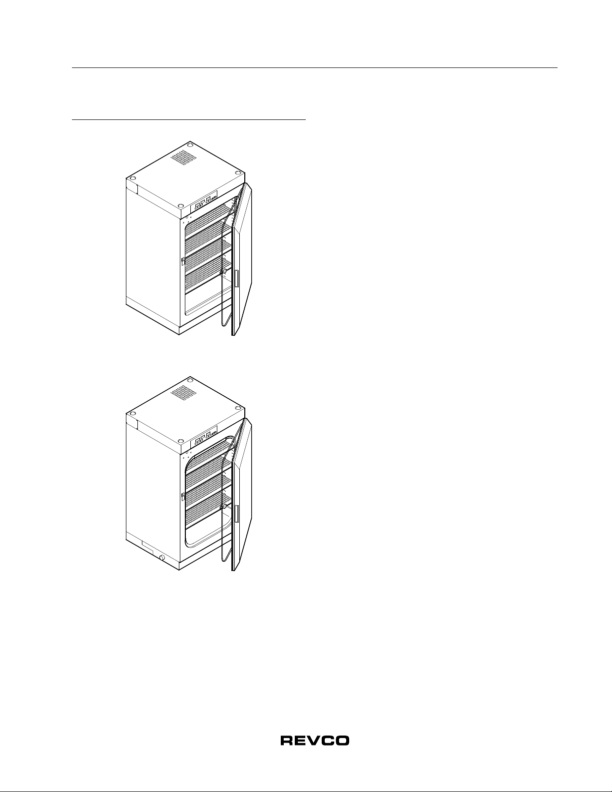
Installation and Operation
Ultima II and Elite II Incubators
2
2 Safety Precautions
In this manual and on labels attached to this product, the words
WARNING and CAUTION mean the following:
•WARNING: a potentially hazardous situation which, if not
avoided, could result in serious injury or death.
•CAUTION: a potentially hazardous situation which, if not
avoided, may result in minor or moderate injury or damage to
the equipment.
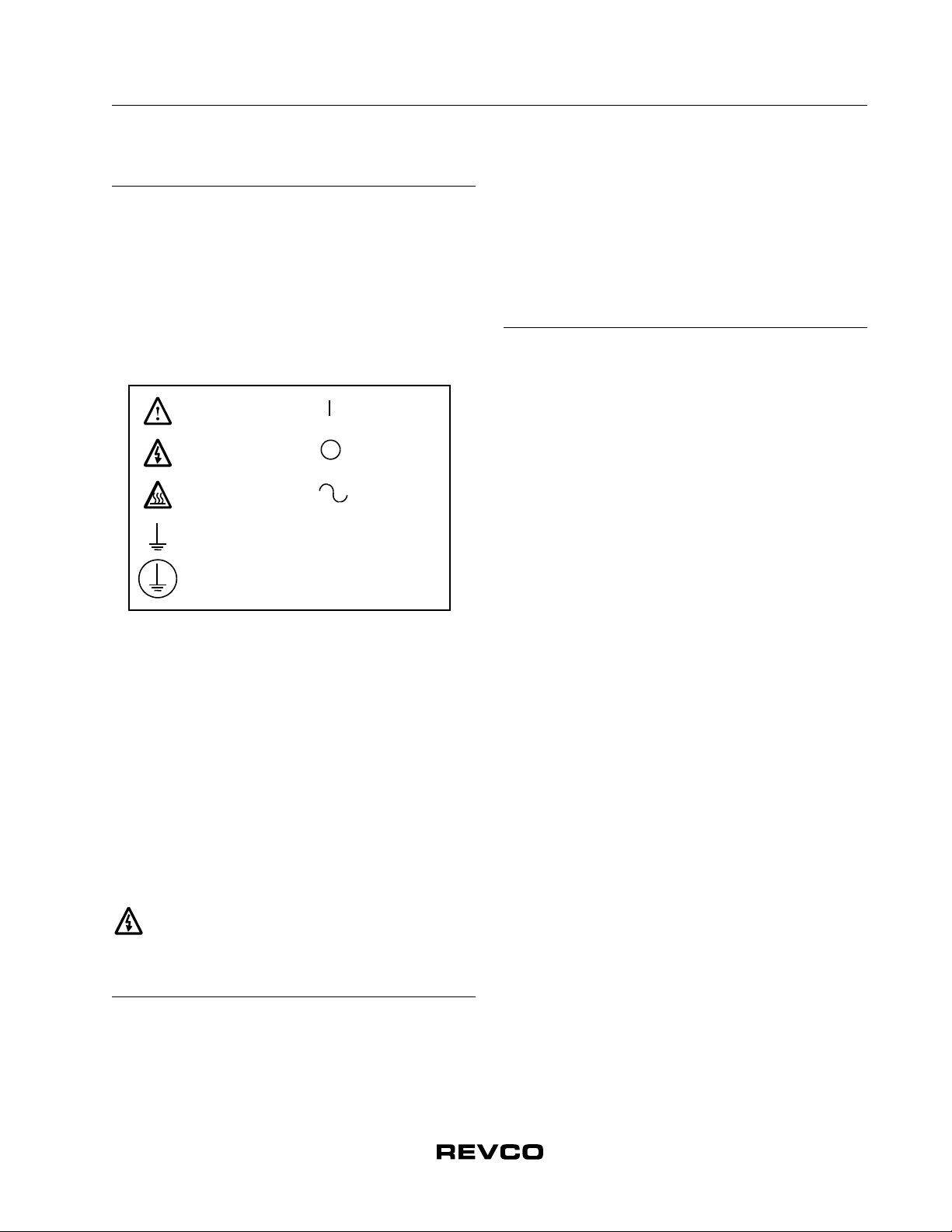
The following symbols are used in caution, warning and
informational labels attached to the incubator:
Before installing, using or maintaining this product, please be sure
to read this manual and product warning labels carefully. Failure to
follow these instructions may cause this product to malfunction,
which could result in injury or damage.
Below are important safety precautions that apply to this product:
•Use this product only in the way described in the product
literature and in this manual. Before using it, verify that this
product is suitable for its intended use.
•Do not modify system components, especially the controller.
Use OEM exact replacement equipment or parts. Before use,
confirm that the product has not been altered in any way.
•Disconnect the unit from all power sources before cleaning,
troubleshooting, or performing other maintenance on the
product or its controls. To disconnect power supply to the
incubator, unplug the supply cord at the back of the incubator.
Note that turning the key switch on the front control panel to
the Off position is not sufficient to disconnect power.
WARNING! The user is responsible for carrying out
appropriate decontamination procedures when
hazardous materials are spilled on or inside the
incubator.
3 Operating Standards
The incubators described in this manual are classified for use as
stationary equipment in a Pollution Degree 2 and Overvoltage
Category II environment, according to the UL61010A-1 and IEC
664 standards.
These units are designed to operate under the following
environmental conditions:
•Indoor use
•Altitude up to 2000m
•Maximum relative humidity 80% for temperatures up to 31ºC
•Main supply voltage fluctuations not to exceed 10% of the
nominal voltage.
4 Pre-Installation
4.1 Unpacking
At delivery, examine the exterior for physical damage while the
carrier’s representative is present. If exterior damage is present,
carefully unpack and inspect the unit and all accessories for
damage. If there is no exterior damage, unpack and inspect the
equipment within five days of delivery. If you find any damage,
keep the packing materials and immediately report the damage to
the carrier. Do not return goods to the manufacturer without
written authorization. When submitting a claim for shipping
damage, request that the carrier inspect the shipping container
and equipment.
4.1.1 Included Parts
The following items are packaged and shipped inside the
incubator cabinet:
•Shelves and shelf brackets
•3/16 in. (476 mm) ID clear tubing for the gas connection (a Y
fitting is also supplied with dual-chamber units)
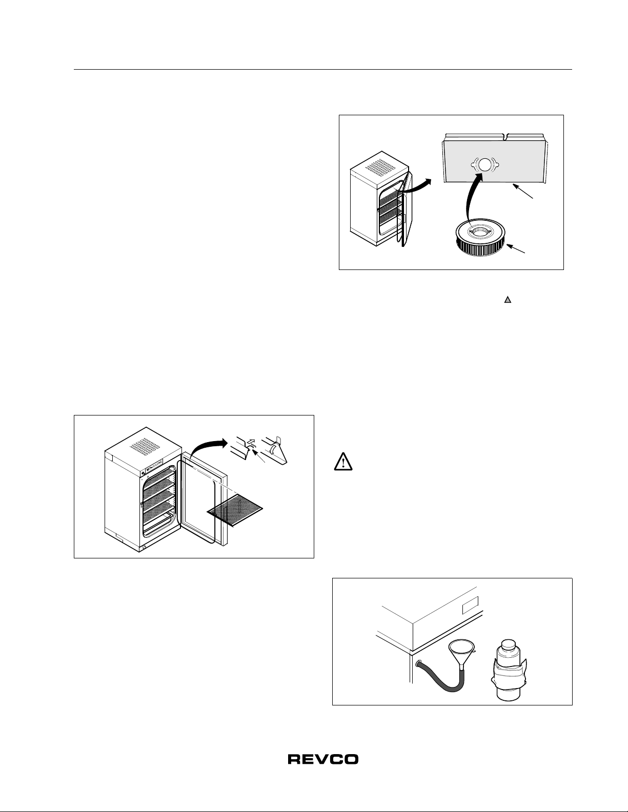
•Decontamination kit: 0.3 micron gas filter, replacement
Blower Wheel, CO2Sensor gasket, and Injection Port
Assembly gasket
•Tubing, funnel, and bottle of water conditioning crystals for
filling the water jacket
•Humidity pan
•HEPA filter (if one comes with your unit)
•A thin, 1/2” open-end wrench to adjust leveling legs and
relocate the outer door hinge
•Stacking brackets (for dual models)
4.2 Set-up
Remove shelves from the inside of the incubator and clean the
incubator (refer to Section 8.1 on page 14). The shelves and
brackets can be autoclaved at this time.
4.3 Location
Install the unit in a level area free from vibration with a minimum
of three inches (7.6 cm) of space on the sides and rear and
12 inches (30.5 cm) at the top. The floor must be able to support
40 PSI (single chamber incubator) or 75 PSI (double chamber
incubator).
Be sure to position the incubator so that the power cord can
easily be reached to disconnect power. Do not position the
equipment in direct sunlight or near any HVAC duct/diffusers.
The ambient temperature range at the location must be 59 to
90°F (15 to 32°C).
caution, info
electrical hazard
hot surface
earth ground
protective conductor terminal
on
off
alternating
current