Reveal NE3613HSSV User manual

Rev A Date: 02/24/2022
User Manuals\Reveal_NE(L)(H)HSSV_Slide-In Htd Self-Svc Case_User Manual_21-26059.pub
SCC P/N
21-26059
USER
MANUAL
REVEAL® SLIDE-IN SELF-SERVICE HEATED MERCHANDISERS
> REAR SLIDING DOOR UNITS WITH PERFORATED PLENUMS THAT SLIDE IN TANDEM WITH DOORS
> SOLID BACK UNITS WITH FIXED METAL PERFORATED PLENUMS
> CAUTION! DO NOT PUSH OR PULL ON UPPER GLASS ENCLOSURE!
> ONLY USE HANDLES (AT EACH END OF CASE) TO PUSH OR PULL CASE INTO POSITION!
Reveal
®
READ AND SAVE THESE INSTRUCTIONS
Model NE4835HSSV Slide-In Unit Shown With
Solid Perforated Metal Back and 3 Shelves
(Illustration Shown May Not Reflect Every
Feature Or Option of Your Particular Case)
Important! See Structural Concepts
Reveal® Self-Service Counter Guide
P/N 21-26260 (That Accompanies This
Manual) For Cabinetry Construction/
Design Requirements. Model NE4835HSSV Slide-In Unit Shown With
Rear Sliding Doors and 3 Shelves
(Illustration Shown May Not Reflect Every
Feature Or Option of Your Particular Case)
Structural Concepts Corporation ∙ 888 E. Porter Road ∙ Muskegon, MI 49441
Phone: 231.798.8888 ∙ Fax: 231.798.4960 ∙ www.structuralconcepts.com

2
TABLE OF CONTENTS
TABLE OF CONTENTS …………………………………………………………………………………...…...
REVEAL® FREE STANDING HEATED SELF-SERVICE MODEL APPLICABILITY &
DIMENSIONS ....………………………………………………………………………………………..
REVEAL® SLIDE-IN SELF-SERVICE HEATED MODEL APPLICABILITY & DIMENSIONS ....……..
INSTALLATION: DISCONNECTION/REMOVAL OF CASE FROM SKID / REVIEW CASE
SURROUNDINGS ……………………………………………………………………………….……..
INSTALLATION, CONT’D: SHELVING ASSEMBLIES / SHELVING RETAINER CLIP REMOVAL ...
INSTALLATION, CONT’D: PLUG IN UNIT / MAIN POWER SWITCH AND LED LIGHT SWITCH .....
CASE DESIGN & FIELD SERVICE PARTS LIST: CASE FRONT AND REAR VIEWS ……….………
CASE DESIGN & FIELD SERVICE PARTS LIST, CONT’D: ELECTRICAL BOX COMPONENTS ....
CASE DESIGN & FIELD SERVICE PARTS LIST, CONT’D: HEATER / DECKS / BAFFLE / AIR
DEFLECTOR ………………………………………………………………………………..….……….
CASE DESIGN & FIELD SERVICE PARTS LIST, CONT’D: SHELVING ASSEMBLY COMPONENTS
CASE DESIGN & FIELD SERVICE PARTS LIST, CONT’D: LED LIGHT / PLUG / THERMOMETER ..
CASE DESIGN & FIELD SERVICE PARTS LIST, CONT’D: REAR PIKE DOORS / REAR
PERFORATED PLENUM DOORS ………………………………………………...…….…….....….
CASE STARTUP / HEATER SETTINGS / LIGHTS SWITCH / SHUTTING DOWN CASE .……………
PRODUCT PLACEMENT / AIRFLOW CONSIDERATION / LOAD LINES ………………………….…..
CLEANING SCHEDULE (TO BE PERFORMED BY STORE PERSONNEL) ..…....…...…………...….
PREVENTIVE MAINTENANCE (TO BE PERFORMED BY TRAINED SERVICE PROVIDER) ……....
TROUBLESHOOTING (TO BE PERFORMED BY STORE PERSONNEL ONLY) ...………………......
TROUBLESHOOTING (TO BE PERFORMED BY TRAINED SERVICE PROVIDERS ONLY) ……….
CAREL PROGRAMMABLE CONTROLLER INFORMATION …………………………………………….
SERIAL LABEL INFORMATION & LOCATION ..…………………………….……...…....……………..…
TECHNICAL SERVICE CONTACT INFORMATION & WARRANTY INFORMATION ...…...…...….....
2
3
4-5
6
7
8
9
10
11
12
13
14
15
16
17
18
19-20
21-22
23-25
26
27

3
REVEAL® SLIDE-IN SELF-SERVICE HEATED MODEL APPLICABILITY & DIMENSIONS
Model Upper Display Case
Height
Overall Case
Height Case Depth x Width
NE3613HSSV 13 5/8” 32 7/8” 33”D x 35 3/4”W
NE3620HSSV 20 3/8” 39 5/8” 33”D x 35 3/4”W
NE3627HSSV* 27 7/8” 47 1/8” 33”D x 35 3/4”W
NE3635HSSV* 35 1/4” 54 5/8” 33”D x 35 3/4”W
NE4813HSSV 13 5/8” 32 7/8 33”D x 47 3/4”W
NE4820HSSV 20 3/8” 39 5/8” 33”D x 47 3/4”W
NE4827HSSV* 27 7/8” 47 1/8” 33”D x 47 3/4”W
NE4835HSSV* 35 1/4” 54 5/8” 33”D x 47 3/4”W
*Taller units have a heater rod and additional fans in upper section as well as two (2) programmable controllers.

4
OVERVIEW / DISPLAY TYPE I vs. II / COMPLIANCE / WARNINGS / PRECAUTIONS - PAGE 1 of 2
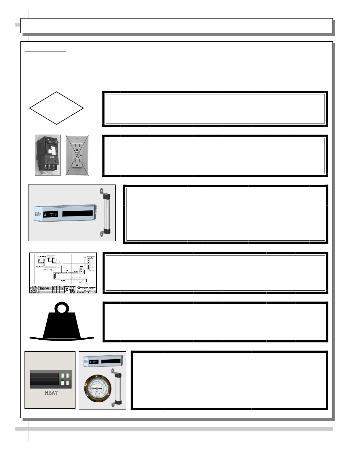
WARNING
Risk of electric shock. Disconnect power before servicing unit.
CAUTION! More than one source of electrical supply may be
employed with units that have separate circuits.
Disconnect ALL ELECTRICAL SOURCES before servicing.
WARNING
ELECTRICAL
HAZARD
OVERVIEW
These Structural Concepts Reveal® heated cases
are designed to hold pre-heated, perishable,
packaged foods at 140 °F to 180 °F (60 °C to 82 °C).
Cases should be installed and operated according to
this operating manual’s instructions to insure proper
performance. Improper use will void warranty.
Product must be pre-heated before placing in
merchandiser. This case is NOT designed to heat
product from cold or ambient conditions.
All heating elements are thermostat controlled for
individual adjustment.
COMPLIANCE
This equipment MUST be installed in compliance with
all applicable NEC, federal, state and local
electrical and plumbing codes.
THERMOMETER
Thermometers in equipment reflect internal air
temperature only (not actual food temperature).
Use probe thermometers to determine actual product
temperatures.
COMPLIANCE
Performance issues when in violation of applicable
NEC, federal, state and local electrical and plumbing
codes are not covered by warranty. See below.
WARNINGS
Please read the important warnings in this document
carefully as they can prevent injury or death.
See next page for PRECAUTIONS.
ATTENTION
CONTRACTORS
WARNING: This product can expose you to chemicals, including
Urethane (Ethyl Carbamate), which are known to the state of
California to cause cancer and birth defects or other reproductive
harm. For more information go to P65Warnings.ca.gov.
WARNING
Decks and shelves may be hot! Disconnect and allow to cool
before cleaning or removing from case.
WARNING
HOT
SURFACE

5
OVERVIEW / DISPLAY TYPE I vs. II / COMPLIANCE / WARNINGS / PRECAUTIONS - PAGE 2 of 2
PRECAUTIONS
Following are important precautions to prevent damage to unit or merchandise.
Please read carefully!
CAUTION! LAMP REPLACEMENT GUIDELINES
LED lamps reflect specific size, shape and overall design.
Any replacements must meet factory specifications.
CAUTION
WIRING DIAGRAM FORMAT & LOCATION
Each case has its own wiring diagram folded & in its own packet.
Wiring diagram placement may vary; it may be placed near field
wiring box, raceway, or other related location.
CAUTION!
DO NOT RELY ON THERMOMETERS OR THERMOSTATS
FOR ACTUAL PRODUCT (FOOD) TEMPERATURES.
Thermometers and thermostats reflect air temperatures ONLY.
For PRECISE food temperatures, use calibrated food
thermometers ONLY.
CAUTION! GFCI BREAKER USE REQUIREMENT
If N.E.C. (National Electric Code) or your local code
requires GFCI (Ground Fault Circuit Interrupter) protection,
you MUST use a GFCI breaker in lieu of a GFCI receptacle.
CAUTION!
To prevent sagging or breakage, do not exceed 5 LBS (2.3 KG)
weight load per top glass section (between vertical supports).
To prevent scratching or marring, do not place ANY items on glass.
5
LBS
CAUTION!
DO NOT RELY ON THERMOMETERS OR THERMOSTATS
FOR ACTUAL PRODUCT (FOOD) TEMPERATURES.
Thermometers & thermostats reflect air temperature ONLY.
For ACTUAL food temperatures, use a calibrated food
thermometer.

6
INSTALLATION: DISCONNECTION & REMOVAL OF CASE FROM SKID / REVIEW CASE SURROUNDINGS
1. Disconnect Case From Skid
Remove screws from shipping brackets.
Remove and discard shipping brackets from
Skid.
Place J-bar/pry under base frame.
Raise case up from Skid to take weight off
casters.
With case raised, lower casters all the way
down against Skid (see next step for detailed
instructions on lowering or raising casters).
Remove rubber shipping blocks.
Skid
Support case
while removing
from Skid
Handles
2. Carefully Remove Case From Skid
Use handles to carefully slide case to
rear of Skid (see illustration at right).
Caution! 4 people may be required
for this task!
Carefully lower to floor. Slide Skid
from under case.
Maintain support of case at all
times or center of gravity may
cause case to fall.
Skid
Rubber Shipping
Blocks (Typ.)
Shipping
Bracket (Typ.)
3. Review Case Surroundings
Check if case is affected by
HVAC vents or outside door
airflow. If so, such airflow must
be prevented from entering the
case.
Otherwise, the case’s ‘air
screen’ may be compromised
causing unsafe food
temperatures.
See sample illustrations shown
at right.
Sample
HVAC Vents

7
INSTALLATION, CONT’D: SHELVING ASSEMBLIES / SHELVING RETAINER CLIP REMOVAL
4. Shelving Assemblies
Shelving retainer clips help secure shelves during
shipping
After case is in place & level (before startup),
you must remove shelving retainer clips.
See illustration below.
Check that glass shelving is in proper position before
placing product in case
Shelves may be adjusted vertically or entirely removed
from merchandiser.
Metal shelving brackets ARE NOT able to be angled.
From Factory: Transparent 2-Sided Tape Holds
Glass To Top Of Rear Shelf Support Rail Shelving Retainer Clip
(Typ.) Is To Be Removed
After Case Is In Place and
Level (Before Startup)

8
INSTALLATION, CONT’D: PLUG IN UNIT / MAIN POWER SWITCH AND LED LIGHTS SWITCH
5. Handles On Sides of Case
Side handles MAY remain on case if space
allows. Otherwise, they may be removed.
See “Space For Countertop” specifics below.
If removed from case, keep handles in safe place
for future possible case relocation use.
6. Shelving Retainer Clips To Be Removed
Important Note: If you have not done so already,
after case is in place and level (before startup),
you must remove shelving retainer clips.
See previous page for illustration.
7. Plug Case In
Check field access box for factory-supplied
power cord.
Plug case into electrical outlet.
See illustration below.
8. Main Power Switch / LED Light Switch
Main power switch and LED lights switch is
accessible at case rear electrical box.
Depending upon model, heater configuration may
vary (as illustrated below).
9. Upper and Lower Rear Panel
Upper rear panel may be lifted off magnets.
Remove lower rear panel by using (2) finger
holes to grasp, lift up and off case.
Return in rear panels in reverse order they were
removed.
See illustration below.
Handles
Note: Model
NE4835HSSV
Slide-In Unit
(Shown) May Not
Exactly Reflect
Every Feature or
Option of Your
Particular Case.
Space For
Countertop
- OR -
**
Lower Rear
Panel
Upper Rear
Panel
*Note: Only taller units have upper and lower heaters (with two programmable controllers). All others have only ONE
heater (with ONE programmable controller).
**If “HUMIDITY” etching is on faceplate, simply ignore; such markings are not applicable to cases in manual.
*
*

9
CASE DESIGN & FIELD SERVICE PARTS LIST: CASE FRONT AND REAR VIEWS
1. Front and Rear Views
Model NE4835HSSV Slide-In unit with rear sliding doors is illustrated below.
Solid back units differ from unit shown.
Model NE4835HSSV Slide-In Unit
(Shown) May Not Exactly Reflect
Every Feature or Option of Your
Particular Case.
FIELD SERVICE PARTS LIST: CASE FRONT AND REAR VIEWS
P/N COMPONENT NAME AMT P/N COMPONENT NAME AMT
1UV-BONDED GLASS ASSEMBLY 14AIR DEFLECTOR 1
2FAN (IN UPPER AIRFLOW SYSTEM)* 5* 5REAR LOWER PANEL 1
3HEATER ROD** 1**
12
4
Rear Upper
Panel
5
Handles (Typ.)
Magnets For Rear
Upper Panel (Typ.)
*Number of fans vary depending upon model.
**Note: Only taller models have a heater rod (accompanied by a separate programmable controller).
3

10
CASE DESIGN & FIELD SERVICE PARTS LIST, CONT’D: ELECTRICAL BOX COMPONENTS
2. Thermostat / LED Driver / Lights / Main
Power Switch
Remove rear lower panel by lifting up and off; no
screw removal is required.
Remove 4 screws from the controller/DC driver
box cover to access electrical components.
* Note: Only taller models have upper AND lower heaters (requiring two programmable controllers). All others have
only ONE heater (with ONE programmable controller).
Electrical Box
(With Faceplate Attached)
Electrical Box
(With Faceplate Removed)
Note: Only certified electricians are to access
electrical components in case.
After accessing controller, return components to
case in reverse order they were removed.
Model NE4835HSSV Slide-In Unit
(Shown) May Not Exactly Reflect
Every Feature or Option of
Your Particular Case.
FIELD SERVICE PARTS LIST: ELECTRICAL BOX COMPONENTS
P/N COMPONENT NAME AMT P/N COMPONENT NAME AMT
6RELAYS 29PROGRAMMABLE CONTROLLERS 2*
7DRIVER 110 LIGHTS SWITCH 1
8TERMINAL STRIP 111 MAIN POWER SWITCH 1
67
10 11
9
8

11
CASE DESIGN & FIELD SERVICE PARTS LIST, CONT’D: HEATER / DECKS / BAFFLE / AIR DEFLECTOR
3. Tub Area Access / Heater / Airflow Baffle & Deflector
Caution! Turn main power off before accessing heater components.
To access tub area (including heater) remove sub-deck and deck pans.
No screw removal is required.
After cleaning or servicing, return sub-deck & deck pans to case.
Restore power to case.
Air Discharge
Baffle Sub-Deck
FIELD SERVICE PARTS LIST: HEATER / DECKS / BAFFLE / AIR DEFLECTOR
P/N COMPONENT NAME AMT P/N COMPONENT NAME AMT
12 HEATER STRIP 214 DECK PAN 2
13 HEATER FAN (HOUSING SHOWN X-PARENT) 3*
--- Case Rear ---
--- Case Front ---
Air Deflector
Model NE4835HSSV Slide-In Unit
(Shown) May Not Exactly Reflect
Every Feature or Option of
Your Particular Case.
12
Heater Fan Assembly
(Shown Transparent)
13
*Number may vary depending upon model.
14

12
CASE DESIGN & FIELD SERVICE PARTS LIST, CONT’D: SHELVING ASSEMBLY COMPONENTS
4. Shelf Assembly Components
Note: After case is in place & level (before startup),
remove shelfing retainer clips (sample clip shown
below-right).
Check that glass shelving is in proper position before
placing product in case
Shelves may be adjusted vertically or entirely removed
from merchandiser.
Metal shelving brackets ARE NOT able to be angled.
They are at a fixed 90° position.
These components comprise EACH shelf assembly.
FIELD SERVICE PARTS LIST: SHELVING ASSEMBLY COMPONENTS
P/N COMPONENT NAME AMT P/N COMPONENT NAME AMT
15 GLASS, LEFT/RIGHT HAND 220 SHELF GUARD, FRONT POLYCARBONATE* 1
16 SHELF GUARD, REAR POLYCARBONATE* 121 LIGHT, LED 1
17 SHELF SUPPORT RAIL, OUTER** 222 BRACKET, RIGHT HAND 1
18 SHELF SUPPORT RAIL, INNER 223 THUMB SCREW, SHELF SUPPORTS 4
19 BRACKET, LEFT HAND 224 BUMPER STAND 8
* Polycarbonate does NOT need to be removed to remove shelf assemblies from case.
** Assembled with shelf support rail, inner (item #18) and thumb screw (item #23) before leaving the factory.
23
1
21
16 24
From Factory: Transparent 2-Sided Tape Holds
Glass To Top Of Rear Shelf Support Rail
Shelving Retainer Clips
Are To Be Removed
After Case Is In Place &
Level (Before Startup)
15
20
19
18
17
22

13
CASE DESIGN & FIELD SERVICE PARTS LIST, CONT’D: LED LIGHT / PLUG / THERMOMETER
5. LED Light
LED lights are located at both header and
shelving of case (as shown below).
Check that ALL of the light plugs are properly
connected to the LED light.
See TROUBLESHOOTING section in manual
if LED lights malfunction.
6. LED Light Plug
LED lights are located at both header and
shelving of case (as shown below).
Check that ALL plugs are properly connected to
the LED lights.
Plug must be inserted ALL THE WAY into the
LED light orifice (with no gap) to work properly.
7. Thermometer
Thermometer provides air temperature of
heated section of case.
Thermometers DOES NOT provide actual food
temperature.
Use probe thermometer to
determine actual product
temperatures.
Model NE4835HSSV Slide-In Unit
(Shown) May Not Exactly Reflect
Every Feature or Option of
Your Particular Case.
FIELD SERVICE PARTS LIST: LED LIGHTS / PLUGS / THERMOMETER
P/N COMPONENT NAME AMT P/N COMPONENT NAME AMT
25 LED LIGHT (ALSO CALLED OUT
ON PREVIOUS PAGE) 127 THERMOMETER 1
26 PLUG, LED LIGHT 1
25
26
27

14
CASE DESIGN & FIELD SERVICE PARTS LIST, CONT’D: REAR PIKE DOORS / PERF. PLENUM DOORS
8. Rear Sliding Pike Doors (With Brackets)
Rear sliding pike doors also control perforated
plenum via inner bracket (as illustrated below).
To remove rear sliding doors, move them toward
center of case.
Individually lift each door up toward the top of the
case; pivot the bottom of the door out.
Return doors to case in reverse order they were
removed.
Inner Bracket To Control
Inner Perforated Plenum
FIELD SERVICE PARTS LIST: REAR SLIDING PIKE DOORS / PERFORATED PLENUM SLIDING DOORS
P/N COMPONENT NAME AMT P/N COMPONENT NAME AMT
28 PIKE DOOR, OUTER WITH INNER BRACKET,
REAR-LEFT 130 PERFORATED SLIDING DOOR, INNER 2
29 PIKE DOOR, OUTER WITH INNER BRACKET,
REAR-RIGHT 1
9. Rear Sliding Inner Perforated Doors
Rear sliding inner perforated doors are shown
below.
To remove, slide toward center of case.
Individually lift each door up toward the top of the
case; pivot the bottom of the door out.
Return perforated doors to case in reverse order
they were removed.
28
30
29
30

15
CASE STARTUP / HEATER SETTINGS / LIGHTS SWITCH / SHUTTING DOWN CASE
1. Main Power Switch
Control panel (at case rear) is accessible after
removal of lower-rear panel.
Turn main power switch “ON” to energize case.
2. Heating Up Case / Adjusting Settings
Note: Cases are designed to MAINTAIN product
temperatures – NOT heat up product! Do not place
product that is cold or ambient temperature in case.
Before placing pre-heated food in case, allow
1 1/2 hours (90-minutes) for case to achieve its
desired temperature.
If adjusting heater settings, allow 20 minutes at
new settings for temperature to affect product.
3. Light Switch
Control panel (at case rear) is accessible after
removal of lower-rear panel.
Turn lights switch “ON” to turn on lights.
All LED lights will come on at the same time.
4. Shutting Down Case
Remove all product from case.
Turn main power switch to “OFF” position.
Caution! Deck and shelving are hot. Allow case
to cool for 45 minutes before cleaning.
Note: When main power is turned back on, you do
NOT need to re-enter settings. Temperatures will
revert back to your LATEST SETTINGS before
shutdown.
Programmable
Controllers*
Model NE4835HSSV Slide-In Unit
(Shown) May Not Exactly Reflect
Every Feature or Option of
Your Particular Case.
Lights
Switch
Main Power
Switch
*Note: Only taller units have upper and lower heaters (with two programmable controllers). All others have only ONE
heater (with ONE programmable controller).
> If “HUMIDITY” etching is on faceplate, simply ignore; such markings are not applicable to cases in user manual.

16
START-UP AND OPERATION, CONTINUED: LOAD LIMITS
16
PRODUCT PLACEMENT / AIRFLOW CONSIDERATION / LOAD LINES
See illustration below.
Caution! For discharged air to reach the return air
grille, you must not block front OR rear grilles with
product.
Do not place product on front ledge of case.
3. Load Lines
Load lines represent the limit that product can be
place (either horizontally or vertically) and/or
stacked in case.
Keep product at or under load lines to assure that
heated airflow is properly cycled from air diffuser
through return air grille.
Proper product placement will maintain
acceptable product temperature.
See illustration below.
1. Product Placement
Product can be placed on decking or steps
(risers) within the service display area.
A wide range of product may be displayed.
2. Air Diffuser Grille & Return Air Grille
Considerations
Proper airflow is critical to maintain proper
product temperature.
Proper product placement will allow discharged
air to flow over (and around) product to the
return air grille (at case rear) AS WELL AS the
upper airflow circulation system. See illustration
below.
Angled View Of
Discharge Air Grille
Load Lines
1” Minimum
Load Line
1” Minimum
Load Line
Model NE3620HSSV (Shown)
May Not Exactly Reflect Every
Feature or Option of Your
Particular Case. However,
General Airflow Consideration
and Load Line Guidelines Apply.
Caution!
2” Air Return
Grille At Rear
Inner.
Do Not Block!
Model NE3620HSSV Shown Below
Load Lines
Caution!
Do Not Place
Product On
Discharge Air
Grille or Ledge
Product Stop
Sample
Product (Typ.)
Discharge Air
Grille
Ledge
Upper Airflow
Circulation
System Sample
Product (Typ.)
Airflow Direction of
Upper Airflow
Circulation System

17
CLEANING SCHEDULE (TO BE PERFORMED BY STORE PERSONNEL)
FREQ. INSTRUCTIONS
Daily Glass Surfaces (Including Shelves): Clean glass surfaces and shelves with household or
commercial glass cleaner.
Daily Rear Sliding Door Exterior Glass: Clean with household or commercial glass cleaner. Clean out
rear door track with moist cloth.
Daily Decks: Wipe off decks with moist cloth dipped in mild soap and water solution.
Daily Stainless Steel Surfaces:
Wash with a solution of hand dishwashing liquid detergent and water or a solution of baking
soda and water. Rinse and polish dry with paper towel or soft cloth.
Never use scouring powders or steel wool as they will scratch stainless steel.
Brighten by polishing with a cloth dipped in vinegar or in ammonia; sprinkle baking soda on
sponge and rub gently; rinse. Polish dry with paper towel.
Remove streaks or heat stains from stainless steel by rubbing with club soda.
Quarterly Under Case Cleaning:
Remove front and/or lower rear panel.
Use broom or vacuum to remove all dust, dirt, food particles or residue from underside of case.
For units with optional humidification system, check overflow; if it needs to be emptied or
cleaned, do so.
Replace front and/or lower rear panel after cleaning.

18
FREQ. INSTRUCTIONS
Quarterly Tub Area:
Caution! Turn off power to case. Allow case to cool for 45 minutes before proceeding.
Remove sub-deck and deck pans.
Wipe down tub area.
Return subdeck and deck pans to case.
Restore power to case.
WARNING! TURN OFF CASE BEFORE PERFORMING PREVENTIVE MAINTENANCE!
PREVENTIVE MAINTENANCE (TO BE PERFORMED BY TRAINED SERVICE PROVIDER)

19
TROUBLESHOOTING (TO BE PERFORMED BY STORE PERSONNEL) - PAGE 1 OF 2
CONDITION TROUBLESHOOTING
Fan Noise Is
Excessive
Call service provider.
Case is Not
Holding Proper
Temperature
If a large amount of cool (or ambient) product was added to the case, it will take time
for the temperature to adjust. Product must be pre-heated before placing in case.
Check air return grilles (area at front of decking) for obstructions.
DO NOT set product on air grilles as this will prevent proper airflow!
See PRODUCT PLACEMENT / AIRFLOW CONSIDERATION / LOAD LINES
section in manual for product placement guidelines.
Check that the case is not in the sun or directly under HVAC/air conditioner ducts.
See OVERVIEW / DISPLAY TYPE I vs. II / COMPLIANCE / WARNINGS /
PRECAUTIONS section in this manual for specifics.
If case still is not holding proper temperature, call service provider.
Check all fans to confirm that all are operating.

20
TROUBLESHOOTING (TO BE PERFORMED BY STORE PERSONNEL) - PAGE 2 OF 2
CONDITION TROUBLESHOOTING
Case Lights
Not Working
Check that light switch is in the ON position.
See INSTALLATION, CONT’D: PLUG IN UNIT / TURN ON MAIN POWER SWITCH
AND LED LIGHT SWITCH section in manual for switch location (regardless of
case design).
If case is not hard-wired, check that power cord is properly connected to wall outlet.
Check that ALL of the light plugs are properly connected to the LED light.
Plug must be inserted ALL THE WAY into the LED light orifice (with no gap).
See illustrations below-left.
Power may not be reaching the case.
Contact store management to have trained service provider perform troubleshooting.
Troubleshooting to be performed by trained service providers only is on next page.
If case light still do not come on, it may need to be replaced.
Contact Structural Concepts’ Technical Service Department for replacement light
(see TECHNICAL SERVICE section of this manual for contact information).
To replace, disconnect plug from existing LED light. Disconnect LED light from its
brackets. Replace with new LED light. Insert plug ALL THE WAY into LED light orifice.
No Gap
Gap
LED Light
Plug
This manual suits for next models
7
Table of contents
Other Reveal Display Case manuals
Popular Display Case manuals by other brands

Hatco
Hatco Glo-Ray GRHD-2P Replacement parts list

Moducase
Moducase DF30 manual

Displays2go
Displays2go RPHLTH Assembly instructions

Eurocryor
Eurocryor SPRING operating manual

Hussmann Chino
Hussmann Chino Entyce TY3 Installation & operation guide

Kysor/Warren
Kysor/Warren VALZER KW installation instructions