2
TABLE OF CONTENTS
TABLE OF CONTENTS …………………………………………………………………………………...…...
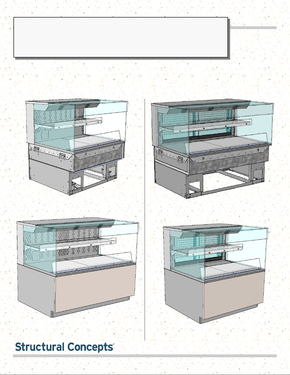
REVEAL® FREE STANDING HEATED SELF-SERVICE MODEL APPLICABILITY &
DIMENSIONS ....………………………………………………………………………………………..
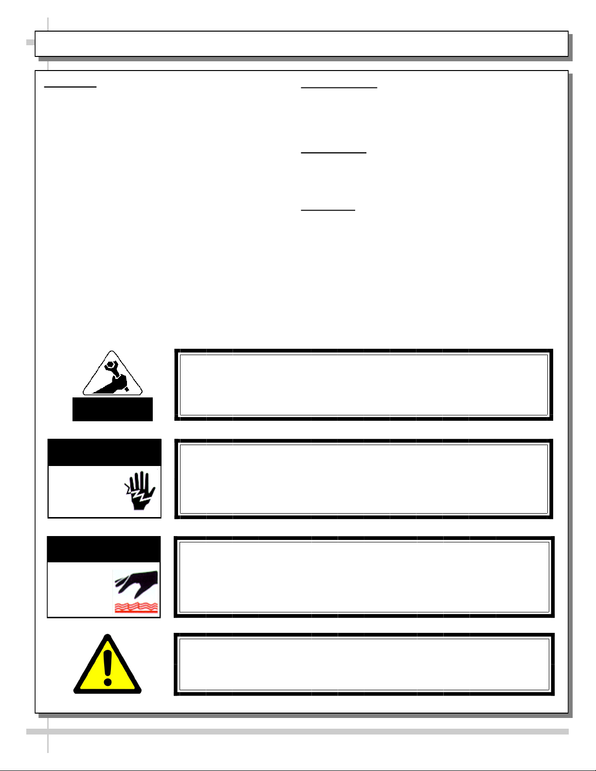
OVERVIEW / DISPLAY TYPE I vs. II / COMPLIANCE / WARNINGS / PRECAUTIONS ……………...
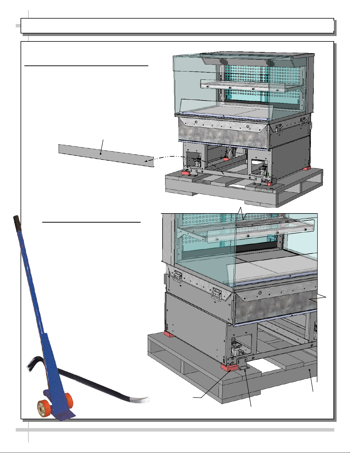
INSTALLATION: TOE-KICK REMOVAL / DISCONNECTING CASE FROM SKID ...……..…………...
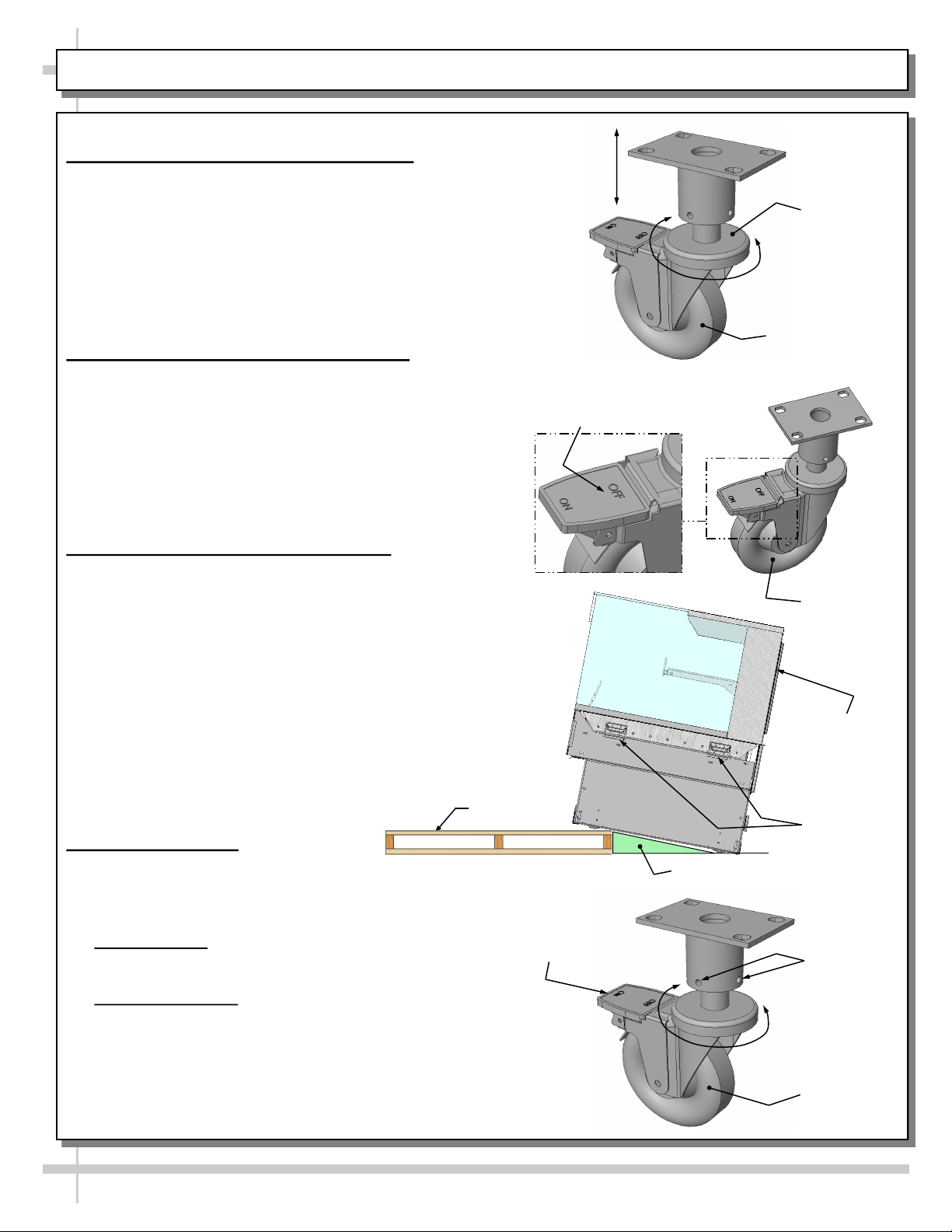
INSTALLATION, CONT’D.: CASTER ADJUSTMENT / LOCK / UNLOCK / CASE REMOVAL
FROM SKID .………………………………………………………………………………...………….
INSTALLATION, CONT’D: SHELVING ASSEMBLY COMPONENTS ...………………………………...
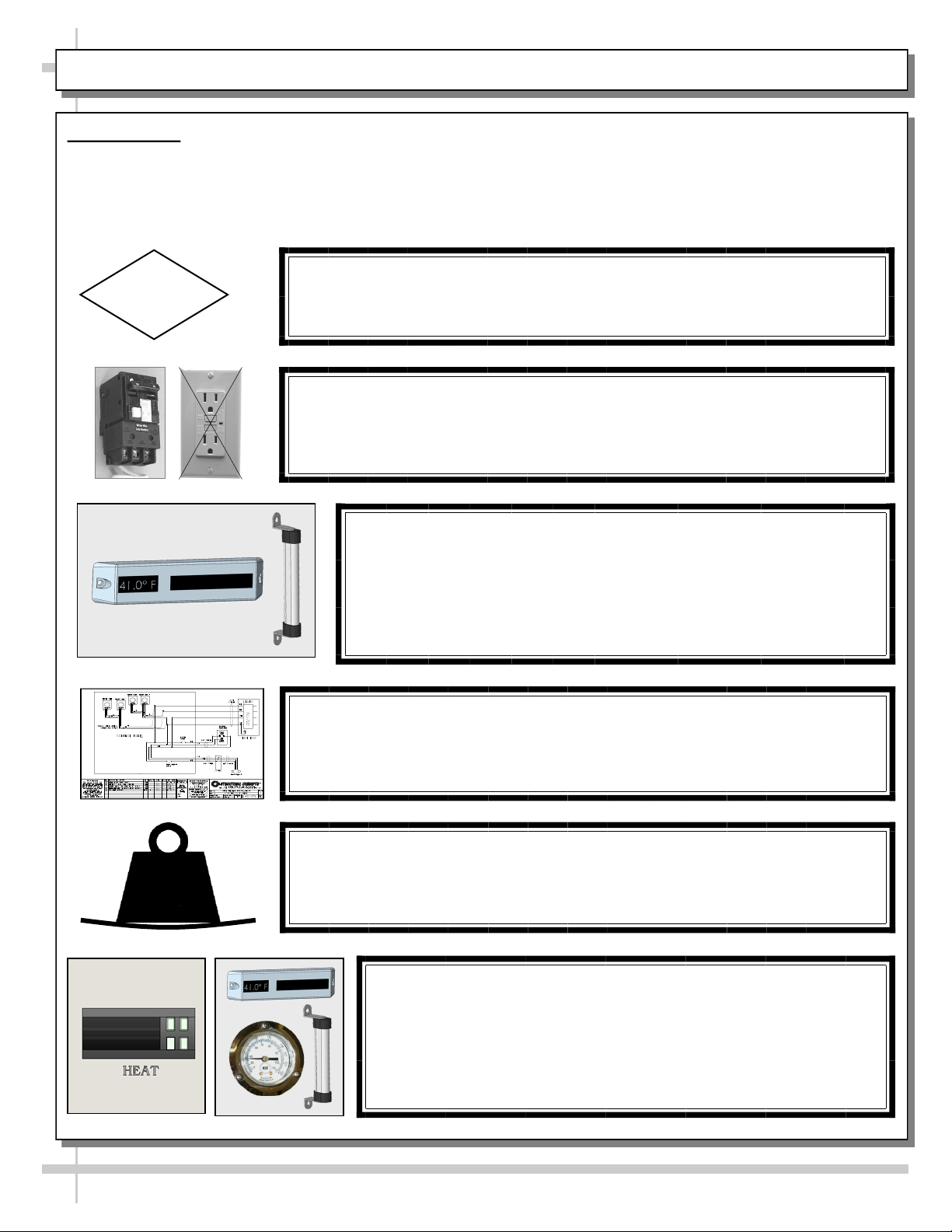
INSTALLATION, CONT’D: PLUG IN UNIT / TURN ON MAIN POWER SWITCH AND LED LIGHTS
SWITCH …………………………………………………………….....……………………………..….
INSTALLATION, CONT’D: ATTACHING FRONT PANEL COMPONENTS …………………....……….
INSTALLATION, CONT’D: ATTACHING SIDE PANELS AND REAR UPPER/LOWER PANELS …..
CASE DESIGN & FIELD SERVICE PARTS LIST: CASE FRONT VIEW ………………..………………
CASE DESIGN & FIELD SERVICE PARTS LIST, CONT’D: CASE REAR VIEW ……………..……….
CASE DESIGN & FIELD SERVICE PARTS LIST, CONT’D: ELECTRICAL BOX COMPONENTS .…
CASE DESIGN & FIELD SERVICE PARTS LIST, CONT’D: HEATER / DECKS / BAFFLE / AIR
DEFLECTOR ……………………………………………………………………………………………..
CASE DESIGN & FIELD SERVICE PARTS LIST, CONT’D: SHELVING ASSEMBLY COMPONENTS
CASE DESIGN & FIELD SERVICE PARTS LIST, CONT’D: LED LIGHT / PLUG / THERMOMETER ..
CASE DESIGN & FIELD SERVICE PARTS LIST, CONT’D: REAR PIKE DOORS / PERFORATED
PLENUM DOORS ……………………………………………………………………………………...
CASE STARTUP / HEATER SETTINGS / LIGHTS SWITCH / SHUTTING DOWN CASE ..…………..
PRODUCT PLACEMENT / AIRFLOW CONSIDERATION / LOAD LINES ………………………….…..
CLEANING SCHEDULE (TO BE PERFORMED BY STORE PERSONNEL) ..…....…...…………...….
PREVENTIVE MAINTENANCE (TO BE PERFORMED BY TRAINED SERVICE PROVIDER) ……....
TROUBLESHOOTING (TO BE PERFORMED BY STORE PERSONNEL ONLY) ...………………......
TROUBLESHOOTING (TO BE PERFORMED BY TRAINED SERVICE PROVIDERS ONLY) ……….
CAREL PROGRAMMABLE CONTROLLER INFORMATION …………………………………………….
SERIAL LABEL INFORMATION & LOCATION ..…………………………….……...…....……………..…
TECHNICAL SERVICE CONTACT INFORMATION & WARRANTY INFORMATION ...…...…...….....
2
3
4-5
6
7
8
9
10
11
12
13
14
15
16
17
18
19
20
21
22
23-24
25-26
27-29
30
31