5
REVEL Concerta F12
Owner’s Manual
ABOUT THE F12
Thank you for purchasing the Revel
Concerta F12 Floor-Standing Loudspeaker.
A full-frequency reproducer, the F12 delivers
accurate performance with wide frequency
range, low distortion and high output
across the entire audible spectrum. F12
loudspeakers are ideally suited as main
speakers in stereo system setups or as the
front speakers in a multichannel surround
home theater installation. Four proprietary
transducers, sophisticated filter networks
and an acoustically inert cabinet allow the
F12 to achieve precise imaging and impres-
sive performance befitting the most
demanding home entertainment systems.
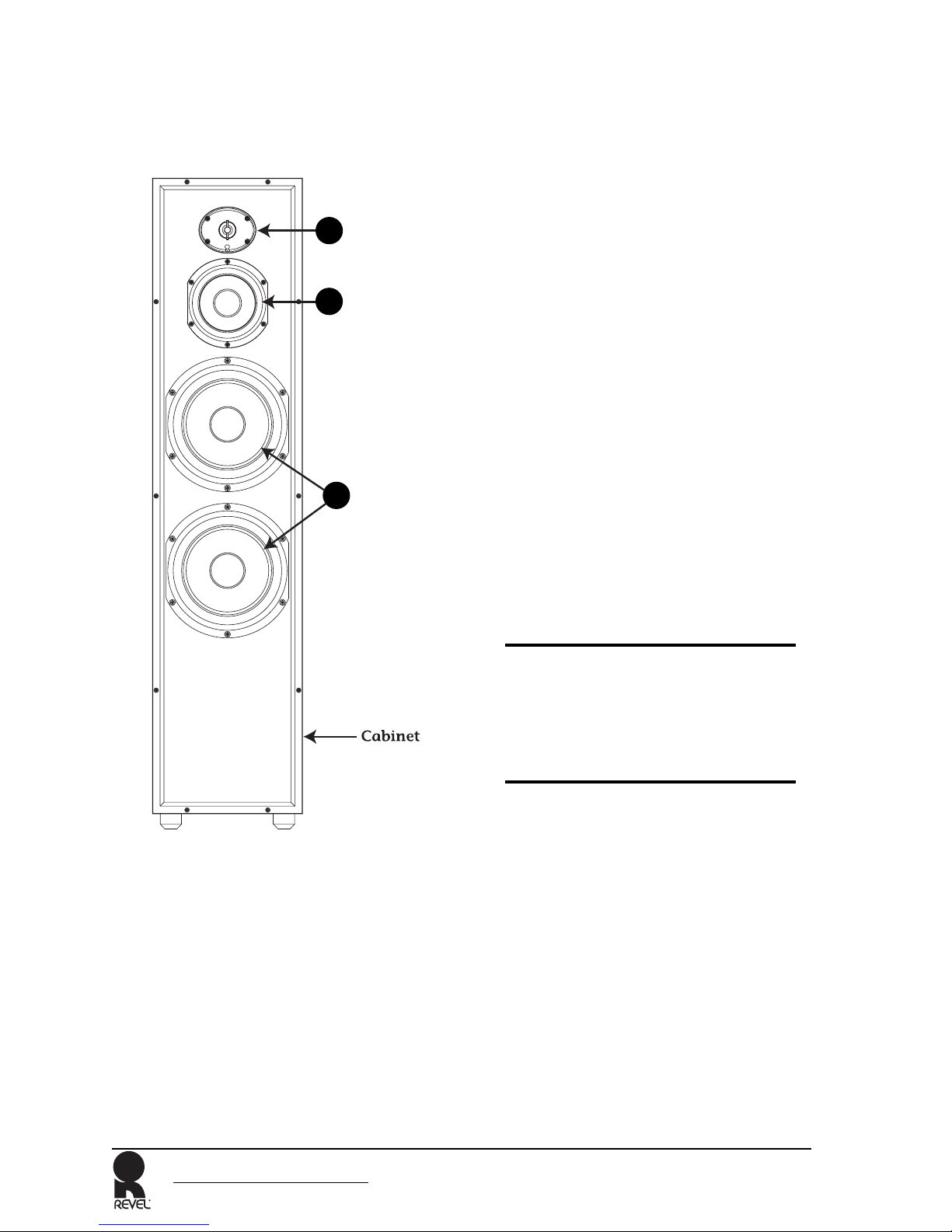
As a three-way loudspeaker, the F12 trans-
ducers effectively cover the entire audible
spectrum. Two 8-inch (203.2mm) woofers
deliver highly refined and dynamically
authoritative low frequencies down to the
lowest octaves. Housed in its own
sub-enclosure, a 5.25-inch (133.35mm)
midrange handles critical mid-band fre-
quencies with natural tonal balance over a
wide dynamic range. A 1-inch (25mm)
dome tweeter reproduces high frequencies
to above audible frequencies. The tweeter
is mounted in a proprietary Controlled
Acoustic Impedance waveguide which opti-
mizes the off-axis response of the system.
The result is superior coherency and musi-
cal realism.
Combining superior form and function,
the F12 loudspeaker’s proprietary drivers
feature a distinctive design that allows for
smoother frequency response. The woofer,
midrange and tweeter cones are construct-
ed with Organic Ceramic Composite
diaphragm material which helps to reduce
distortion. The spiders are constructed with
a high-strength Nomex/cotton blend with
optimized geometry for increased linearity.
The woofer and midrange also include
butyl rubber surrounds that provide for
large, linear excursion capabilities.
The midrange is built with a 1-inch
(25mm) voice coil with a high-temperature
bobbin that enables high-power handling.
The midrange features optimized and
shielded magnetic circuits to minimize
harmonic distortion and prevent monitor
interference.
The woofer includes a copper voice coil
wound on a 1.5-inch (38mm) Kapton®
bobbin that enables higher power
handling. The woofer is also constructed
with a vented center pole for increased
high-temperature cooling and low com-
pression.
The tweeter dome is under-hung with
copper-clad aluminum wire to prevent
distortion. The tweeter’s magnet contains
Ferrofluid® which helps to achieve higher
power handling with reduced compression.
The tweeter is also magnetically shielded
to prevent video monitor interference.
High-order filters at 575Hz and 3.0kHz
optimize loudspeaker on-axis and off-axis
response, helping to ensure smooth octave-
to-octave balance and timbral accuracy.
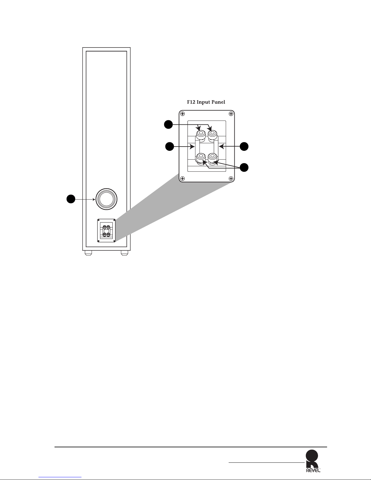
Removable shorting-straps and gold-plated
binding posts accommodate single-wired,
bi-wired and bi-amplified connections.
The F12 cabinet is constructed with medi-
um-density fiberboard (MDF) walls to
reduce cabinet-induced resonances. Rubber
feet are attached to the bottom of the cabi-
net to accomodate installations on tile or
hardwood floors. Optional (included) spikes
can be inserted into the feet for placement
on carpeted surfaces.